
Subscribe to Our Youtube Channel
Related Manuals for DINA DNDSmodular


Summary of Contents for DINA DNDSmodular
- Page 1 Original Betriebsanleitung Original Instruction Manual Metallgehäuse Kunststoffgehäuse Metal housing Synthetically housing Wir sind Sicherheit. We are safety...
- Page 2 EU-Konformitätserklärung EU declaration of conformity Dichiarazione di conformità UE Dichiarazione di conformità UE Declaración UE de conformidad Die nachfolgend aufgeführten Produkte sind konform mit den Anforderungen der folgenden Richtlinien The beneath listed products are in conformity with the requirements of the following directives Les produits mentionnés ci-dessous sont conformes aux exigences imposées par les directives suivantes I prodotti sotto elencati sono conformi alle direttive sotto riportate Los productos listados a continuación son conforme a los requisitos de las siguientes directivas...
-
Page 3: Table Of Contents
Inhaltsverzeichnis S Contents DNDS Modular Module DNDS Modular modules Bestimmungsgemäße Verwendung Intended purpose Zertifizierungsdaten 4 Certification data Sicherheitsbestimmungen Safety regulations Wichtiger Hinweis und Validierung 6 Important notes and validation Ergänzungen nach DIN EN ISO 13849-1 Additions according 13849-1 Aufbau Mounting Produktvarianten Product variants Gerätebeschreibung... -
Page 4: Dnds Modular Modules
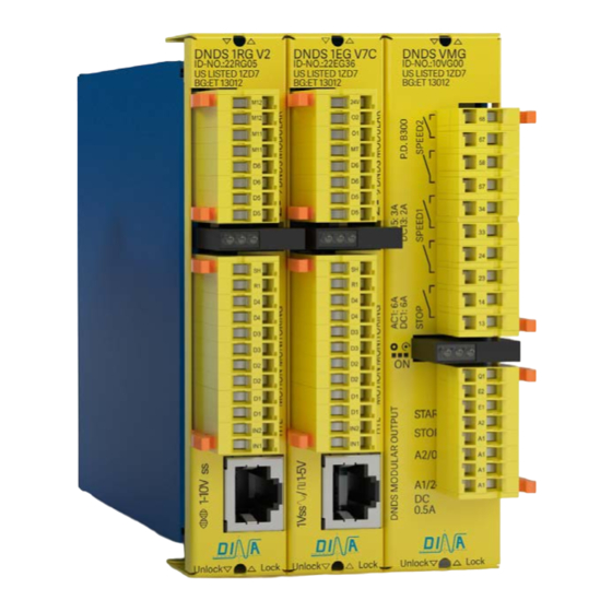
DNDS Modular Original Betriebsanleitung Original Instruction Manual DNDS Modular Module DNDS Modular modules Metallgehäuse Ausgangsmodul Eingangsmodule Kunststoffgehäuse Ausgangsmodul Eingangsmodule Metal housing Output modules Input modules Synthetically housing Output modules Input modules DNDS DNDS DNDS DNDS DNDS DNDS 1M–8M 1E V6 1PMG-8PMG 1EG V7 1PM–8PM... -
Page 5: Safety Regulations
• Bei nicht Einhaltung dieser Vorschriften, akzeptiert • If these regulations are not adhered to or in the DINA Elektronik GmbH keinerlei Ansprüche für die event of improper use, DINA Elektronik GmbH Entstehung von Personen oder Sachschaden. accepts absolutely no liability for the resulting property damages or personal injury. -
Page 6: Important Notes And Validation
• DINA Elektronik ist nicht in der Lage, • DINA Elektronik is not in the position to guarantee die Eigenschaften eines Gesamtsystems zu the properties of a complete system that was not garantieren, das nicht von DINA konzipiert. -
Page 7: Additions According 13849-1
DNDS Modular Original Betriebsanleitung Original Instruction Manual Ergänzungen nach DIN EN ISO 13849-1 Additions according 13849-1 • Die Grenzen des SRP/CS beginnen an den Eingangssig- • The boundaries of the SRP/CS start at the input nalklemmen und enden an den Klemmen der kontakt- signals clamps and will end at the clamps of the behafteten Freigabepfade. -
Page 8: Mounting
STOP 1-5V 300KHz A2 0V Module guideway Module guideway 1VSS 1Vpp 0.5A DINA ELEKTRONIK D-72649 WOLFSCHLUGEN Einstellung am Rack Adjustment at the rack DNDS GM, GMG DNDS GM, GMG DNDS Modul links vom GM, GMG Beide Module links vom GM,... -
Page 9: Product Description
DNDS Modular Original Betriebsanleitung Original Instruction Manual Gerätebeschreibung Product Description • DNDS arbeitet mit einer Betriebsspannung von 24V DC. • DNDS works with24V DC power supply. • Das Gerät ist zur Montage auf einer 35mm Hutschiene. • The unit is mountable on a 35mm DIN rail. •... -
Page 10: Function Of The Terminals
DNDS Modular Original Betriebsanleitung Original Instruction Manual Funktion der Klemmen Function of the terminals • IN1, IN2 für 2 PNP Sensoren als Messsystem. • IN1, IN2 for 2 PNP sensors as measuring system. • Anschluss IN2 an 24V, IN1 offen: unterdrückt •... -
Page 11: Setting Of The Divisor Via S1 And S2, Switch On Position 1
DNDS Modular Original Betriebsanleitung Original Instruction Manual Einstellung des Teilers über S1 und S2, Position 1 - 8 Setting of the divisor via S1 and S2, switch on position 1 - • Der Teiler dient der Anpassung der Messsystem- • The divisor has to adapt the frequency of the measuring frequenz an den gewählten Frequenzwert am Ein- system to the selected frequency at the input module. -
Page 12: Important Remarks
Für den nicht benötigten Überwachungssteckplatz ist ein Use a bridge connector for the not needed monitoring Brückenstecker bei DINA verfügbar. position. Bridge connector can be ordered by DINA. Überwachung Stilllegen Disable monitoring Bei Bedarf kann eine Überwachung durch prellfreies An- In case if one monitoring system should be disabled, legen des Eingangs IN2 an 24V stillgelegt werden. -
Page 13: Operation
• Messsystem und Eingangsmodul über DINA • Connect the measuring system to the input module Kabeladapter verbinden bzw. 2 Sensoren an IN1 und via DINA cable adaptor respectively 2 sensors to IN2 anschließen. Siehe Sensor Montage. terminals IN1, IN2. See mounting of sensors. -
Page 14: Input Module 1Eg/ 1E V6, V9/ Incremental System
DNDS Modular Original Betriebsanleitung Original Instruction Manual Eingangsmodul 1EG/ 1E V6, V9/ Inkrementelles System Input module 1EG/ 1E V6, V9/ incremental system 1EG V9 1E V6, V9 STOP IN1IN2 D1 D4 SH R1 SPEED Jumper Sin+Cos STOP STOP SPEED SPEED STOP IN1IN2 D1 D4 SH R1... -
Page 15: Selection Of Function Modes
DNDS Modular Original Betriebsanleitung Original Instruction Manual Auswahl von Vmax über D- und F-Klemmen oder inern Selection of Vmax via D- and F-Terminals Klemmen ►24V Terminals ►24V 1 + 5 2 + 6 3+ 7 4+ 8 1 + 5 2 + 6 3 + 7 4 + 8... - Page 16 DNDS Modular Original Betriebsanleitung Original Instruction Manual Eingangsmodul 1EG, 1E, V7, V7A, V7C Input module 1EG, 1E, V7, V7A, V7C 1E V7 1EG V7A 1E V7A 1EG V7C STOP STOP STOP SPEED STOP STOP SPEED SPEED SPEED SPEED 1-5V 300KHz 1-5V 300KHz 1VSS...
- Page 17 DNDS Modular Original Betriebsanleitung Original Instruction Manual Die Frequenzwerte in den unteren Tabellen sind The frequency values in the tables below are: Tabellenwert = Messsystem Frequenz Teiler an S1, S2 Table values = system frequency divisor at S1, S2 Frequenzauswahl für Vmax bei V7 Selection of frequency for Vmax using V7 Auswahl von Vmax im Einricht- und Halbautomatikbetrieb Auswahl von Vmax...
-
Page 18: Function Modes With V7A And V7C
DNDS Modular Original Betriebsanleitung Original Instruction Manual Betriebsarten bei V7A und V7C Function modes with V7A and V7C DNDS alle alle OM, PM GM GM V1 alle alle Betriebsart 1E, 1EG GMG V1 Function SH, R1, 13 14 OS 33 34 OD 53 54 57 58 57 58... -
Page 19: Selection Of Frequency For Vmax Using V7C (22Eg36-01)
DNDS Modular Original Betriebsanleitung Original Instruction Manual Frequenzauswahl für Vmax bei V7C ID-No.: 22EG36-01 Selection of frequency for Vmax using V7C (22EG36-01) Neue Version 26EG36-01 New Version 26EG36-01 Auswahl von Vmax im Einricht- und Halbautomatikbetrieb Auswahl von Vmax im Automatikbetrieb Selection of Vmax for tool setting and semi-automatic mode Selection of Vmax during automatic mode S3 + S5 Position = ON... -
Page 20: Input Module 1Rg/ 1R /Resolver Measuring System
DNDS Modular Original Betriebsanleitung Original Instruction Manual Eingangsmodul 1RG/ 1R /Resolver Messsystem Input module 1RG/ 1R /Resolver measuring system DNDS 1RG V1 DNDS 1R V1 DNDS 1RG V2 DNDS 1R V2 DNDS 1RG V3C STOP STOP STOP SPEED STOP SPEED STOP SPEED SPEED... -
Page 21: Function Modes With V1, V2, V3C
DNDS Modular Original Betriebsanleitung Original Instruction Manual Betriebsarten bei V1, V2, V3C Function modes with V1, V2, V3C DNDS alle alle OM, PM GM GM V1 alle alle Betriebsart 1R, 1RG GMG V1 SH, R1 Function F1-F4 13 14 OS 33 34 OD 53 54 57 58 57 58... - Page 22 DNDS Modular Original Betriebsanleitung Original Instruction Manual Frequenztabelle für Vmax bei 1R, 1RG V1 Selection of Frequency for Vmax using 1R, 1RG V1 Auswahl von Vmax im Einricht- und Halbautomatikbetrieb Auswahl von Vmax über D- & F-Klemmen Selection of Vmax for the tool setting and semi-automatic mode Selection of Vmax via D- & F-Terminals S3+S5 Position = ON S3 + S5 Position = ON D1 –...
-
Page 23: Dnds Pmg And Dnds Om, Pm: Output Modules
Usage: start of the brake 0.5A Bremsvorgangs der Antriebe action of the drives Siehe Wiedereinschaltsperre. See restart interlock. DINA ELEKTRONIK D-72649 WOLFSCHLUGEN LED bei PMG/ PM LED at PMG/ PM • LED links und rechts sind • LED left and right are dark dunkel bei ohne Messsystem. -
Page 24: Dnds Vmg And Dnds Vm: Output Modules
Einsatz: Netztrennung Usage: Net disconnection 0.5A (Stopp Kategorie 1) (Stop category 1) DINA ELEKTRONIK D-72649 WOLFSCHLUGEN Achtung: im Fehlerfall kann die Warning: in case of fault the Zeit verkürzt werden, bzw. die delay time can be shortened or Kontakte fallen sofort ab. - Page 25 DNDS Modular Original Betriebsanleitung Original Instruction Manual SPEED Ausgang ohne SPEED output without SPEED Ausgang mit SPEED output with Wiedereinschaltsperre restart interlock Wiedereinschaltsperre restart interlock V>Vmax. V>Vmax. >2s 13-14, 23-24 13-14, 23-24 33-34, 43-44 33-34, 43-44 57-58, 67-68 57-58, 67-68 >250ms Paralleler Anschluss der Ausgänge Serieller Anschluss der Ausgänge...
- Page 26 • Usage: start of the brake Antriebe action of the drives Siehe auch Wiederein- See also restart interlock. schaltsperre. 0.5A • SPEED2: 53-54/ 63-64 DINA ELEKTRONIK • SPEED2: 53-54/ 63-64 See SPEED1 D-72649 WOLFSCHLUGEN Siehe SPEED 1. • • This output module ena- •...
-
Page 27: Function Mode Diagram
DNDS Modular Original Betriebsanleitung Original Instruction Manual SPEED Ausgang ohne Wiedereinschaltsperre SPEED Ausgang mit Wiedereinschaltsperre SPEED output without restart interlock SPEED output with restart interlock V>Vmax. V>Vmax. >2s 13-14/ 23-24 13-14/ 23-24 33-34/ 43-44 33-34/ 43-44 53-54/ 63-64 53-54/ 63-64 V innerhalb 0.5s kleiner 90% von Vmax V nach 0.5s größer 90% von Vmax V during 0.5s less than 90% of Vmax... - Page 28 STOP SPEED A2/0V 1-5V 300KHz A1/24V 0.5A 1VSS 1Vpp DINA ELEKTRONIK D-72649 WOLFSCHLUGEN Metall Metal Kunststoff Synthetically Rack Varianten/ Gewicht/ Breite Rack Varianten/ Gewicht/ Breite Rack variants/ Width/ Wight Rack variants/ Width/ Wight type type DNDS 1PMG...
- Page 29 DNDS Modular Original Betriebsanleitung Original Instruction Manual Technische Daten Elektrische Anforderungen Betriebsspannung U 24V DC Spannungstoleranz U 90 - 110% Restwelligkeit U (DC) maximal 10% Leistungsaufnahme bei U maximal 10W Eingangsspannung / Eingangsstrom 24VDC / 1.5mA / 90 – 110% Sicherheitskontakte STOP 14, 23...
-
Page 30: Technical Data
DNDS Modular Original Betriebsanleitung Original Instruction Manual Technical Data Operating voltage U 24 V DC Voltage tolerance U 90 - 110% Residual ripple U (DC) max 10 % Power consumption at U max 10 W Safety contacts STOP all output modules 13 1423 24 SPEED 1 all output modules 33 3443 44... - Page 31 DNDS Modular Original Betriebsanleitung Original Instruction Manual wir sind sicherheit. DINA Elektronik GmbH Esslinger Str. 84 D 72649 Wolfschlugen Phone +49 7022 9517-0 +49 7022 9517-700 info@dina.de www.dina.de Sicherheitstechnik Stand 19.02.2018 Date 2018-02-19 Seite 31 von 31 page 31 of 31...
Need help?
Do you have a question about the DNDSmodular and is the answer not in the manual?
Questions and answers