Table of Contents
Advertisement
Available languages
Available languages
Quick Links
Einbau- und Betriebsanleitung
Installation and Operating instructions
Instructions de montage et de service
Digitaler Stellungsregler mit Antriebskontrolle
Digital Positioner with actuator control
Positionneur digital
Inhaltsverzeichnis
1
2
3
4
5
Funktionsbeschreibung
6
Content
1
2
3
4
5
6
Index
1
2
3
4
5
6
1
2
07/2009
3581-8010
Baureihe / Series / Séries
RE 3581 DAC
2
2
3
5
5
8
9
9
9
12
12
15
16
16
17
20
20
23
24
25
®
Advertisement
Table of Contents

Related Manuals for RTK DAC RE 3581 Series


Summary of Contents for RTK DAC RE 3581 Series
-
Page 1: Table Of Contents
Einbau- und Betriebsanleitung 3581-8010 Installation and Operating instructions Instructions de montage et de service Baureihe / Series / Séries Digitaler Stellungsregler mit Antriebskontrolle RE 3581 DAC ® Digital Positioner with actuator control Positionneur digital Inhaltsverzeichnis Allgemeine Informationen Montage und Anschluß Inbetriebnahme Funktionsbeschreibung Funktionsbeschreibung... -
Page 2: Allgemeine Informationen
Einbau- und Betriebsanleitung 3581-8010 Installation and Operating instructions Instructions de montage et de service Allgemeine Informationen Der RE 3581 (Digital Actuator Control) positioniert den Antrieb in Abhängigkeit des anstehenden Eingangssignals. Hierzu benötigt der Regler eine Potentiometerrückmeldung über den gesamten Hub des Antriebes. Er hat einen integrierten Meßumformer der das Potentiometersignal in ein stetiges Ausgangssignal 4..20mA umwandelt. -
Page 3: Inbetriebnahme
Einbau- und Betriebsanleitung 3581-8010 Installation and Operating instructions Instructions de montage et de service Inbetriebnahme Die Inbetriebnahme darf erst erfolgen, wenn die Anschlüsse wie unter Kapitel 2.1 Elektrischer Anschluß beschrieben korrekt erfolgt sind. Bei Auslieferung mit Ventil ist der Regler werkseitig eingestellt. Eine erneute Anpassung an den Ventilhub ist nicht notwendig. Der Regler ist sofort betriebsbereit. - Page 4 Einbau- und Betriebsanleitung 3581-8010 Installation and Operating instructions Instructions de montage et de service 3.3 Ablaufschema der Initialisierung Alle 3 Taster gleichzeitg drücken bis alle LEDs leuchten Wenn blinkt, Initialisierungsdaten gelöscht! drücken Passwort eingeben (siehe unten) Achtung: 4..20mA Bei 2-Weg Ventilen muß nein Passwort ok? Hub 100% manuell...
-
Page 5: Funktionsbeschreibung
Einbau- und Betriebsanleitung 3581-8010 Installation and Operating instructions Instructions de montage et de service 3.4 unüberwachter Handbetrieb Nach korrekter Eingabe des Paßwortes kann das Ventil im Handbetrieb mit den "Öffnen" und "Schließen" Tasten bewegt werden. Fahren sie das Ventil in Mittelposition +/- 20%. Die Initialisierung darf auf keinen Fall in der Nähe der Endlagen gestartet werden. 4 Funktionsbeschreibung Der Regler arbeitet in 4 verschiedenen Betriebsarten. - Page 6 Einbau- und Betriebsanleitung 3581-8010 Installation and Operating instructions Instructions de montage et de service schließen gefahren Der erster Stellbefehl in Gegenrichtung wird verlängert, bis der Antrieb in Regelstellung steht, also den Ventilsitz verlassen hat 5.3 Kennlinienadaption Ein pendelnder Antrieb wird durch Manipulation der Stellschritte stabilisiert. Das Profil erlernt der DAC durch Adaption während des ®...
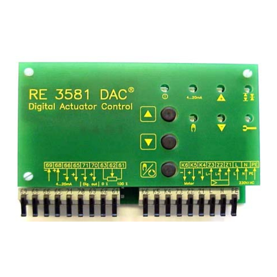
- Page 7 Einbau- und Betriebsanleitung 3581-8010 Installation and Operating instructions Instructions de montage et de service Abb.1:Regler ohne Deckplatte Abgleich Eingang (Nullpunkteinstellung): oder Legen Sie ein 4mA Signal am Stromeingang an und warten bis der Antrieb stehen bleibt. Sollte die 0% Endlage nicht erreicht werden, stellen sie den Regler folgendermaßen ein Taste Hand/Auto gedrückt halten.
-
Page 8: Fehlermeldungen
Einbau- und Betriebsanleitung 3581-8010 Installation and Operating instructions Instructions de montage et de service Taste "Auf" drücken Rückmeldewert wird größer Taste "Zu" drücken Rückmeldewert wird kleiner Stellen Sie genau 4 mA ein. Abgleich Span (Verstärkung/Bereich) oder Legen Sie 20 mA am Stromeingang an und warten bis der Antrieb die 100% Endlage erreicht hat. Taste "Auf"... -
Page 9: General Information
Einbau- und Betriebsanleitung 3581-8010 Installation and Operating instructions Instructions de montage et de service 1 General Information The digital positioner RE 3581 DAC is a microprocessor system which drive the actuator from 0% to 100% with an input signal from ®... - Page 10 Einbau- und Betriebsanleitung 3581-8010 Installation and Operating instructions Instructions de montage et de service 3.1 Delete initialisation data (Reset) Before you can make a new initialisation, you have to delete the present data. Deleting the present data: Press all 3 keys together longer than 10 sec. (All LEDs are lighting). After all LEDs was lighting for 2 sec.
- Page 11 Einbau- und Betriebsanleitung 3581-8010 Installation and Operating instructions Instructions de montage et de service 3.4 Function diagram of the initialisation Press all 3 buttons as long as all lights are on. After a few seconds is flashing push Enter password (see bottom) 4..20mA Attention:...
-
Page 12: Description Of Function
Einbau- und Betriebsanleitung 3581-8010 Installation and Operating instructions Instructions de montage et de service 4 Description of Function The controller is working in 4 different Functions. 4.1 Manual operation Press key the LED is lighting manual operation is switched on. Driving the valve only with the keys on the RE3581 possible. - Page 13 Einbau- und Betriebsanleitung 3581-8010 Installation and Operating instructions Instructions de montage et de service Picture 3: Adapted actuator 5.4 Torque control Valve blockages are immediately recognised and the actuator is stopped. After the next step in the other direction, the actuator is allowed to reverse. 5.5 Command control Every step of the direction of the valve spindle and the result is checked.
- Page 14 Einbau- und Betriebsanleitung 3581-8010 Installation and Operating instructions Instructions de montage et de service step with key "Open" to make the input signal higher step with key "Close" to make the input signal lower Now control the limit position again! Control both values again, to be sure it is correct.
-
Page 15: Error Codes
Einbau- und Betriebsanleitung 3581-8010 Installation and Operating instructions Instructions de montage et de service Error codes Blockage in closing direction Actuator was blocked during closing. 4..20mA LEDs Blockage and Close are flashing alternately. Flashing indications disappears with the next step in the other direction Blockage in Opening Direction Actuator was blocked during opening... -
Page 16: Informations Générales
Einbau- und Betriebsanleitung 3581-8010 Installation and Operating instructions Instructions de montage et de service Informations générales Le positionneur numérique RE 3581 règle la position de l'actionneur en fonction du signal d'entrée appliqué. Pour ce faire, il a besoin d'un signal de compte rendu potentiométrique, couvrant l'intégralité... -
Page 17: Mise En Service
Einbau- und Betriebsanleitung 3581-8010 Installation and Operating instructions Instructions de montage et de service Raccordement électrique Voir annexe. Mise en service Ne procéder à la mise en service qu'après avoir effectué le raccordement électrique conformément aux instructions du appendix raccordement électrique. En cas de livraison avec la vanne, le positionneur est réglé... - Page 18 Einbau- und Betriebsanleitung 3581-8010 Installation and Operating instructions Instructions de montage et de service 07/2009...
- Page 19 Einbau- und Betriebsanleitung 3581-8010 Installation and Operating instructions Instructions de montage et de service Schéma séquentiel de l'initialisation Enfoncez simultanément les 3 Quand clignote, données d'initialisation effacées Enfoncez allumé Entz mot de passe (voir ci-dessous) Mise en garde. Pour des vannes 2 voies 4..20mA la position de course Passwort ok?
-
Page 20: Modes De Fonctionnement
Einbau- und Betriebsanleitung 3581-8010 Installation and Operating instructions Instructions de montage et de service Modes de fonctionnement Le positionneur fonctionne avec 4 modes de fonctionnement distincts. Mode manuel Enfoncez la touche ; la LED s'allume, mode de fonctionnement "manuel" activé. Commande de la vanne possible uniquement avec les touches du RE 3581. - Page 21 Einbau- und Betriebsanleitung 3581-8010 Installation and Operating instructions Instructions de montage et de service 5.3 Adaptation des paramètres Une commande oscillante se stabilise en modifiant les pas de réglage. Le DAC apprend le profil en s’adaptant pendant le fonctionnement. ® Après l’adaptation, le profil est enregistré...
- Page 22 Einbau- und Betriebsanleitung 3581-8010 Installation and Operating instructions Instructions de montage et de service Ajustage de l'entrée (réglage du zéro) : appliquez un signal 0/4 mA à l'entrée de courant et attendez que l'actionneur s'arrête. Si la position de fin de course 0% n'est pas atteinte, réglez le positionneur de la manière suivante : maintenez la touche Manu/Auto enfoncée , appuyez sur la touche "Ouvrir"...
-
Page 23: Messages D'erreur
Einbau- und Betriebsanleitung 3581-8010 Installation and Operating instructions Instructions de montage et de service Ajustage pleine échelle : appliquez 20 mA à l'entrée de courant et attendez que l'actionneur ait atteint la position 100%, appuyez sur la touche "Ouvrir" pour augmenter le signal de compte rendu, appuyez sur la touche "Fermer"... -
Page 24: Anhang / Appendix/Annexe
Einbau- und Betriebsanleitung 3581-8010 Installation and Operating instructions Instructions de montage et de service Anhang / Appendix / Annexe 1 Elektrischer Anschluß / Electric Connection / Raccordement électrique Z1 an N Z2 an L1 bedeutet Sicherheitsendlage 100% P O T 1 oder Z3 an L1 Sicherheitsendlage 0% Z1, Z2, Z3 nicht angeschlossen: Ventil... -
Page 25: Technische Daten / Technical Data / Caractéristiques Techniques
Einbau- und Betriebsanleitung 3581-8010 Installation and Operating instructions Instructions de montage et de service 2 Technische Daten / Technical data / Caractéristiques techniques Technische Daten Technical data Caractéristiques techniques Signal de commande: 4..20mA R env.. 4..20mA Ri ca. 50 Ω 4..20mA Ri ca.
Need help?
Do you have a question about the DAC RE 3581 Series and is the answer not in the manual?
Questions and answers