Advertisement
Quick Links
T
hermoregulaTion
0676EN June 2016
R
KPM30
egulation unit
KPM30
Description
The KPM30 and KPM31 regulation unit derives from Giacomini's extensive
experience in the field of thermoregulation of heating and cooling
systems. The KPM30 regulation unit is a device designed to be used in
Giacomini radiant heating and/or cooling systems in combination with bus
thermoregulation components and other communicating devices with
compatible protocols. The KPM30 module is equipped with a display and six
multifunctional keys; this allows programming of the system parameters via
a guided menu and the subsequent monitoring of the system by the user.
The KPM30 module allows for quick connection to the ambient thermostats
K492B, K495B and K495L and to the KPM35 expansion boards.
In addition, the operation of the circulator and the activation of the mixing
valve servo-control is managed automatically.
The KPM31 version has the same characteristics as the KPM30 but without
the display, therefore it must be installed in combination with the remote
display KD201 (which is an optional accessory for the KPM30 model). Thanks
to the plug-in terminals and the design compliant with the DIN standard, it
can be installed in accessible electrical panels.
Versions and product codes
The KPM30/KPM31 series is available in different versions:
• KPM30Y001, KPM31Y001: stand alone for the control of one mixing valve
• KPM30Y002, KPM31Y002: stand alone for the control of two mixing valves
• KPM30Y003, KPM31Y003: for the management of one to three ambient
thermostats and control of a mixing valve, a dehumidifier or a fan-coil
• KPM30Y004, KPM31Y004: for the management of one to sixteen thermostats
and control of a mixing valve and seven air treatment machines (to be used
in combination with the KPM35 expansion boards)
• KPM30Y005, KPM31Y005: for the management of one to sixteen thermostats
and control of two mixing valves and seven air treatment machines (to be
used in combination with the KPM35 expansion boards)
No. of mixing
Product code
valves
KPM30Y001
1
KPM31Y001
KPM30Y002
2
KPM31Y002
KPM30Y003
1
KPM31Y003
KPM30Y004
1
KPM31Y004
KPM30Y005
2
KPM31Y005
KPM31
and
KPM31
No. of ambient
No. of air
thermostats
treatment machines
-
-
-
-
1÷3
1
1÷16 (with KPM35)
7 (with KPM35)
1÷16 (with KPM35)
7 (with KPM35)
Main features
Mechanical characteristics
Dimensions: all versions are available on DIN rail mounting 6 modules of
105x115x60 mm
Plastic housing
• DIN rail mounting in accordance with DIN 43880 and CEI EN 50022
• Material: technopolymer
• Self-extinguishing: V2 (according to UL94) and 960 °C (according to IEC 695)
• Ball pressure test 125 °C
• Resistance to creeping current ≥ 250 V
• Grey RAL7035
Electrical characteristics
• Insulated power supply:
- DC power supply: 48 Vdc (36 Vmin...72 Vmax)
- AC power supply: 24 Vac +10/-15 %, 50/60 Hz
- Maximum absorption: P=11W, P=14VA, Imax=700 mA
• CPU: H8SX/1651 32-bit, 50 MHz
• FLASH program memory: 2+2 MByte
• SRAM data memory: 512 Kbytes organized in 16-bit
• EEPROM parameter data memory: 13 kByte + 32 kB
• NAND FLASH memory: 32 MByte
• Working cycle duration: 0,2 s typically (applications of average complexity)
• Clock: available as standard and integrated on the base
Battery characteristics
The battery used in the KPM30/KPM31 is "button" type lithium, code CR2430,
voltage 3Vdc and dimensions 24x3 mm.
Technical data
• Operating conditions: -10÷60 °C, 90 % R.H. non-condensing
• Storage and transportation conditions: -20÷70 °C, 90 % R.H. non-condensing
• Protection degree: IP40 front panel only
• Environmental pollution: 2
• Class according to the protection against electric shock: to be integrated on
Class I and/or II equipment
• Period of electrical stresses of the insulating parts: long
• Type of action: 1 C
• Type of disconnection or microinterruption: microinterruption
• Heat and fire resistance class: Class D (UL94–V0)
• Immunity against voltage surges: Class II
• Ageing characteristics (hours of operation): 80.000
• No. of automatic operating cycles: 100.000 (EN 60730-1); 30.000 (UL 873)
• Software class and structure: Class A
• Surge immunity class: Class III (CEI EN 61000-4-5)
The device is not intended to be hand-held.
Dimensions
A
A [mm]
105
B
B [mm]
C [mm]
60
110
1
Advertisement

Related Manuals for Giacomini KPM30 Series


Summary of Contents for Giacomini KPM30 Series
- Page 1 - Maximum absorption: P=11W, P=14VA, Imax=700 mA Description • CPU: H8SX/1651 32-bit, 50 MHz The KPM30 and KPM31 regulation unit derives from Giacomini's extensive • FLASH program memory: 2+2 MByte experience in the field of thermoregulation of heating and cooling •...
-
Page 2: First Start-Up
KPM30Y001, KPM30Y002, KPM31Y001, KPM31Y002 PROGRAMMING of the regulation unit: Commands Legend Alarm button, allows to analyse the type of alarm and disable it after having fixed the problem PRG button, allows to access the menus ESC button, return to the previous menu DOWN button, allows to navigate the menus UP button, allows to navigate the menus ENTER button, allows to select and confirm... -
Page 3: Main Screen
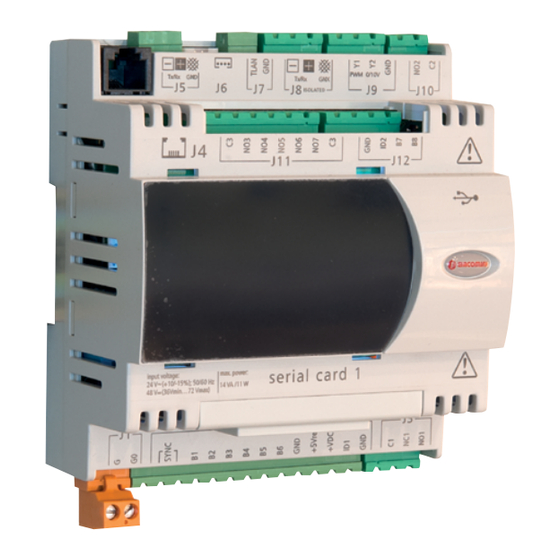
Main screen Service menu The main screen allows a quick check of the The service menu is accessible to the installer only. It allows to modify system's main water mixing functions. additional parameters and reset the guided configuration. Displays time, outside temperature if 1. - Page 4 Terminals J1 - G - G0 24Vac +10/-15% 50/60Hz from safety transformer Class II J2 - SYNC 24Vac +10/-15% 50/60Hz from safety transformer Class II J2 - B1 Delivery probe radiant1 J2 - B2 Delivery probe radiant2 J2 - B3 External probe J2 - B4 Not used...
- Page 5 Electric connections KPM30Y001 / KPM31Y001 With one mixer 0...10 V at 24 Vac...
- Page 6 Electric connections KPM30Y001 / KPM31Y001 With one mixer 3-point floating at 24 Vac...
- Page 7 Electric connections KPM30Y002 / KPM31Y002 With two mixers 0...10 V at 24 Vac...
- Page 8 Electric connections KPM30Y002 / KPM31Y002 With two mixers 3-point floating at 24 Vac...
- Page 9 8. summer regulation: indicate whether from climatic curve, external probe or internal dew point 9. summer climatic curve 10. number of zones present: indicate the number of thermostats connected 11. type of probes/thermostats: indicate the code of the Giacomini thermostat connected 12. number of dehumidifiers 13. number of integrators 14.
- Page 10 Main screen The main screen allows a quick check of the system's main water mixing functions. Displays time, outside temperature if configured, date, the mixing valve displayed, the water temperature, the set water temperature must reach and the mixing valve position as a percentage. Visible symbols: Summer / winter...
- Page 11 Main menu Service menu The sub-menu can be entered via the main menu for the detailed control of The service menu is accessible to the installer only. It allows to modify the system. additional parameters and reset the guided configuration. 1.
- Page 12 Terminals J1 - G - G0 24Vac +10/-15% 50/60Hz from safety transformer Class II J2 - SYNC 24Vac +10/-15% 50/60Hz from safety transformer Class II J2 - B1 Delivery probe radiant1 J2 - B2 Not used J2 - B3 External probe J2 - B4 Not used J2 - B5...
- Page 13 Electric connections KPM30Y003 / KPM31Y003...
- Page 14 8. summer regulation: indicate whether from climatic curve, external probe or internal dew point 9. summer climatic curve 10. number of zones present: indicate the number of thermostats connected 11. type of probes/thermostats: indicate the code of the Giacomini thermostat connected 12. number of dehumidifiers 13. number of integrators 14.
- Page 15 Main screen The main screen allows a quick check of the system's main water mixing functions. Displays time, outside temperature if configured, date, the mixing valve displayed, the water temperature, the set water temperature must reach and the mixing valve position as a percentage. Visible symbols: Summer / winter...
- Page 16 Main menu Service menu The sub-menu can be entered via the main menu for the detailed control of The service menu is accessible to the installer only. It allows to modify the system. additional parameters and reset the guided configuration. 1.
- Page 17 Terminals J1 - G - G0 24Vac +10/-15% 50/60Hz from safety transformer Class II J2 - SYNC 24Vac +10/-15% 50/60Hz from safety transformer Class II J2 - B1 Delivery probe radiant1 J2 - B2 Delivery probe radiant2 J2 - B3 External probe J2 - B4 Not used...
- Page 18 Electric connections KPM30Y004 / KPM31Y004...
- Page 19 Electric connections KPM30Y005 / KPM31Y005...
-
Page 20: R Egulation Unit
For further information, visit the website www.giacomini.com or contact the technical service: ' +39 0322 923372 6 +39 0322 923255 * consulenza.prodotti@giacomini.com This information is intended as an example. Giacomini S.p.A. reserves the right to modify the contents - at any time and without prior warning - for technical or commercial reasons. The information in this technical sheet does not exempt the user from scrupulously observing the existing regulations and standards relating to good technical practices.
Need help?
Do you have a question about the KPM30 Series and is the answer not in the manual?
Questions and answers