Table of Contents
Troubleshooting

Subscribe to Our Youtube Channel
Related Manuals for Ericsson Redback Networks SmartEdge 1200

Summary of Contents for Ericsson Redback Networks SmartEdge 1200
- Page 1 SmartEdge 1200 Router Hardware Guide Release 6.1.3 Part Number 220-0716-05 Corporate Headquarters Redback Networks Inc. 100 Headquarters Drive San Jose, CA 95134-1362 http://www.redback.com Tel: +1 408 750 5000...
-
Page 2: Third Party Software
© 1996 to 2008, Redback Networks Inc. All rights reserved. Redback Networks Redback and SmartEdge are trademarks registered at the U.S. Patent & Trademark Office and in other countries. AOS, NetOp, SMS, and User Intelligent Networks are trademarks or service marks of Redback Networks Inc. All other products or services mentioned are the trademarks, service marks, registered trademarks or registered service marks of their respective owners. -
Page 3: Vcci Class A Statement
VCCI Class A Statement European Community Mark The following marking on this product signifies that it meets all relevant European Union directives. China RoHS Information All Redback Networks products built on or after March 1, 2007 conform to the People’s Republic of China’s Management Methods for Controlling Pollution by Electronic Information Products (Ministry of Information Industry Order #39), also known as “China RoHS.”... -
Page 4: Safety Notices
WEEE Policy Redback Networks products are fully compliant with Directive 2002/96/EC on Waste Electrical and Electronic Equipment (WEEE) for all applicable geographies in the European Union. In accordance with the requirements of the WEEE Directive, Redback Networks has since August 13, 2005 labeled products placed on the market with the WEEE symbol, a crossed-out “wheelie bin”... - Page 5 Varning Eksplosionsfara vid felaktigt batteribyte. Använd samma batterityp eller en ekvivalent typ som rekommenderas av apparattillverkaren. Kassera använt batteri enligt fabrikantens instruktion. Advarsel! Lithiumbatteri—Eksplosionsfare ved fejlagtig håndtering. Udskiftning må kun ske med batteri af samme fabrikat og type. Levér det brugte batteri tilbage tilleverandøren.
-
Page 7: Table Of Contents
Contents About This Guide ................. i Objectives . - Page 8 OC-192c/STM-64c Card ................2-15 Chapter 3: Preparing for Installation .
- Page 9 Connect and Route the Cables at the Front of the Chassis ..........4-31 Connect and Route the External Timing and Power Cables .
- Page 10 Add a Traffic Card ................6-15 Replace a Traffic Card .
-
Page 11: About This Guide
About This Guide This preface contains the following sections: • Objectives • Related Publications • Intended Audience • Organization • Conventions • Navigation Aids • Ordering Documentation Objectives This guide contains all the information you need to prepare the site for, install, and service the hardware for ®... -
Page 12: Intended Audience
Intended Audience • Transceivers for SmartEdge Traffic Cards Describes the transceiver types and their specifications, including cable data, for all traffic cards, and how to install them. • Ports, Circuits, and Tunnels Configuration Guide for the SmartEdge OS Describes the tasks and commands that you use to configure traffic cards, their ports, channels, and circuits, including link groups, bridged and cross-connected circuits, and tunnels. -
Page 13: Conventions
Conventions • Chapter 5, “Determining Operating Status” Describes the SmartEdge 1200 chassis and card LEDs used to determine the status of the system. It also describes how to troubleshoot hardware problems and use the on-demand diagnostics to isolate faults to the card level. •... -
Page 14: Ordering Documentation
Ordering Documentation • Entries in the table of context • Entries in any of the indexes Ordering Documentation Redback documentation is available on a CD-ROM that ships with the following Redback products: • SMS™ products • SmartEdge router products • NetOp EMS and NetOp Policy Management (PM) products The following sections describe how to order additional copies and provide feedback: •... -
Page 15: Chapter 1: System Description
C h a p t e r 1 System Description ® This chapter provides a functional overview of the SmartEdge 1200 router that includes the interfaces, system components, features, and typical applications for the system. It includes the following topics: •... -
Page 16: Router Versions
System Overview Note In the descriptions that follow, the term, controller card, refers to any version of the Cross-Connect Route Processor (XCRP) Controller card (XCRP, XCRP3, XCRP4), unless otherwise noted. The term, Gigabit Ethernet, applies to any Ethernet traffic card that supports a port speed of 1 Gbps or greater;... -
Page 17: Specification Summary
System Overview Specification Summary Table 1-2 summarizes the general specifications for the SmartEdge 1200 router. Table 1-2 General Specifications Specification Value Synchronization • Line timing mode (various traffic cards) • Internal timing mode • External timing mode Protection type • Power: independent dual-feed •... -
Page 18: Alarms
System Components Note Protection for cards and ports is configurable on a per-port basis; a mix of protected and unprotected ports is supported. Protection features and the types of ports that support APS depend on the release of the software. •... -
Page 19: Smartedge 1200 Chassis
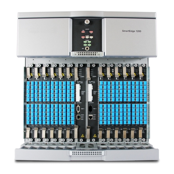
System Components SmartEdge 1200 Chassis The SmartEdge 1200 chassis is designed for mounting in a standard 19- or 23-inch rack. Figure 1-1 shows the standard SmartEdge 1200 chassis; Figure 1-2 shows the SmartEdge 1200n chassis. Main features of the chassis include: •... -
Page 20: Chassis Cooling
System Components Figure 1-2 NEBS-Compliant SmartEdge 1200n Chassis Chassis Cooling Cooling for the chassis is provided by the fan tray, which is installed directly above the card slots. Six fans provide the needed airflow from the bottom of the chassis to the top with exhaust at the rear of the chassis. An air filter is installed below the card cage and filters incoming air before it reaches the cards. -
Page 21: Controller Cards
System Components Controller Cards A controller card manages the system; it is responsible for the packet routing protocols, the SmartEdge OS command-line interface (CLI), and communications with a network management system running the NetOp™ Element Management System (EMS) software. The controller card also loads all configuration information necessary for the traffic cards. - Page 22 System Components Table 1-3 XCRP and XCRP3 Controller Card Comparison (continued) Feature XCRP XCRP3 External storage for core dumps 1 GB 1 GB (NEBS certified) and system files External ports 2 DB-9 (CRAFT 1, CRAFT 2) 2 DB-9 (CRAFT 1, CRAFT 2)3 1 10/100 Ethernet 1 10/100 Ethernet 1.
-
Page 23: Controller Card Features And Functions
System Components Controller Card Features and Functions A controller card has these features and functions: • Processors The XCRP and XCRP3 Controller cards have two processors. One processor runs low-level software, including device drivers and equipment management software; the second processor runs the routing and broadband remote access server (BRAS) software. - Page 24 System Components The time-of-day clock (TDC) for a SmartEdge router is implemented in software. When a system with an XCRP3 or XCRP4 Controller card is powered on, the RTC sets the TDC; otherwise, the TDC is undefined until it is configured and set using the SmartEdge OS. The TDC can be maintained by synchronization with a Network Time Protocol (NTP) server.
- Page 25 System Components • Two types of operations ports for system management access—Craft and Ethernet: — The XCRP and XCRP3 Controller cards have two Craft ports, labeled “CRAFT 1” and “CRAFT 2”; the XCRP4 Controller card has a single Craft port, labeled “CRAFT”. Each port has a DB-9 connector and provides an RS-232 connection to a local console terminal, a terminal server, or a modem.
-
Page 26: Traffic Cards
System Components Figure 1-3 shows the front panels of the controller cards. Figure 1-3 Controller Cards Traffic Cards Table 1-5 lists the traffic cards supported on the SmartEdge 1200 router; for more information about traffic cards, see Chapter 2, “Traffic Card Descriptions.” In the table, the IR abbreviation specifies Intermediate Reach. - Page 27 System Components Table 1-5 SmartEdge 1200 Traffic Cards (continued) Number Number Low-Density Low-Density Protection Type of Traffic Card/Description of Cards of Ports Version Ports Ratios Gigabit Ethernet (first and second versions) None Gigabit Ethernet 3 – None Gigabit Ethernet 1020 (10-port) –...
- Page 28 System Components 1-14 SmartEdge 1200 Router Hardware Guide...
-
Page 29: Chapter 2: Traffic Card Descriptions
C h a p t e r 2 Traffic Card Descriptions ® This chapter describes each of the traffic cards that are currently available for the SmartEdge 1200 router. Asynchronous Transfer Mode (ATM) cards include: • ATM OC-12c/STM-4c Intermediate Reach Card •... - Page 30 A few traffic cards have a low-density version, on which a limited number of ports are enabled through software entitlement. Table 2-1 lists the port data for traffic cards; in the table, IR, LR, and SR abbreviations are used for Intermediate Reach, Long Reach, and Short Reach, respectively. Table 2-1 Port Data for Traffic Cards Physical...
-
Page 31: Atm Oc-12C/Stm-4C Intermediate Reach Card
ATM OC-12c/STM-4c Intermediate Reach Card ATM OC-12c/STM-4c Intermediate Reach Card The Enhanced ATM OC-12c/STM-4c IR card supports one SONET or SDH SMF port, which operates at 622 Mbps, and can be used either as optical line or optical trunk interfaces. In addition, the Enhanced ATM OC-12c/STM-4c IR card can be used to support subscriber circuits. - Page 32 ATM OC-12c/STM-4c Intermediate Reach Card Table 2-2 lists the specifications for the Enhanced ATM OC-12c/STM-4c IR card. Table 2-2 ATM OC-12c/STM-4c IR Card Specifications Specification Value General Number of ports Speed 622.08 Mbps Protection (facility) 1+1 APS: Bidirectional or unidrectional; revertive or nonrevertive switching Interface Telcordia IR-1, SDH/STM-4 S-4.1...
-
Page 33: Atm Oc-3C/Stm-1C Intermediate Reach Card
ATM OC-3c/STM-1c Intermediate Reach Card ATM OC-3c/STM-1c Intermediate Reach Card The ATM OC-3c/STM-1c Intermediate Reach (IR) card supports four SONET or SDH SMF ports, each of which operates at 155 Mbps, and can be used either as optical line or optical trunk interfaces. Figure 2-2 shows the front panel of the ATM OC-3c/STM-1c IR card. - Page 34 ATM OC-3c/STM-1c Intermediate Reach Card Table 2-3 lists the specifications for the 4-port ATM OC-3c/STM-1c IR card. Table 2-3 ATM OC-3c/STM-1c IR Card Specifications Specification Value General Number of ports 2 or 4 Speed 155.52 Mbps Protection 1+1 APS: Bidirectional or unidrectional; revertive or nonrevertive switching Interface Telcordia IR-1, SDH/STM-1 S-1.1...
-
Page 35: 10/100 Ethernet And Fast Ethernet-Gigabit Ethernet Cards
10/100 Ethernet and Fast Ethernet-Gigabit Ethernet Cards 10/100 Ethernet and Fast Ethernet-Gigabit Ethernet Cards The 10/100 Ethernet card provides 12 copper-based 10Base-T or 100Base-TX ports with individually selectable speeds of 10 Mbps or 100 Mbps. The Fast Ethernet-Gigabit Ethernet (FE-GE) card provides 60 copper-based 10Base-T or 100Base-TX ports with selectable speeds of 10 Mbps or 100 Mbps. -
Page 36: Transceiver-Based Gigabit Ethernet Cards
Transceiver-Based Gigabit Ethernet Cards Table 2-4 lists the specifications for the 10/100 Ethernet and FE-GE traffic cards. Table 2-4 10/100 and FE-GE Card Specifications Specification 10/100 FE-GE Number of ports 60 10/100; 2 100/1000 Speed 10 or 100 Mbps 10, 100, or 1000 Mbps (user selectable, auto-sensing) (user selectable, 100 Mbps is auto-sensing) Protection... - Page 37 Transceiver-Based Gigabit Ethernet Cards Gigabit Ethernet ports on these cards require a gigabit interface converter (GBIC), a small form-factor pluggable (SFP), or a 10-Gbps SFP (XFP) transceiver in each port. Table 2-5 lists the transceiver type for each Gigabit Ethernet card. Table 2-5 Transceiver Types for Gigabit Ethernet Cards Traffic Card...
-
Page 38: Gigabit Ethernet And Advanced Gigabit Ethernet
Transceiver-Based Gigabit Ethernet Cards These traffic cards are described in the following sections: • Gigabit Ethernet and Advanced Gigabit Ethernet • Gigabit Ethernet 3 • Gigabit Ethernet 1020 • 10 Gigabit Ethernet Gigabit Ethernet and Advanced Gigabit Ethernet The Gigabit Ethernet and Advanced Gigabit Ethernet cards are the first and second versions of the 4-port Gigabit Ethernet card, respectively. -
Page 39: Gigabit Ethernet 3
Transceiver-Based Gigabit Ethernet Cards Gigabit Ethernet 3 The Gigabit Ethernet 3 (GE3) card is the third version of the 4-port Gigabit Ethernet card. It is designed for traffic management, with the second generation of the PPAs, each of which supports 1 GB of memory and can process data internally at a much higher rate than the PPAs on the first and second versions of the Gigabit Ethernet card. -
Page 40: Gigabit Ethernet 1020
Transceiver-Based Gigabit Ethernet Cards Table 2-8 GE3 Card Base-CWDM and Base-DWDM Specifications Specification CWDM DWDM Number of ports Speed 1 Gbps 1 Gbps Protection None None Interface 1000Base-CWDMnnnn 1000Base-DWDMITUnn Line code 8B/10B 8B/10B Negotiate flow control Transceiver type Compliance IEEE 802.3, 802.3z IEEE 802.3, 802.3z 1. - Page 41 Transceiver-Based Gigabit Ethernet Cards Table 2-9 and Table 2-10 list the specifications for the GE1020 cards for the various SFP transceivers. Table 2-9 GE1020 Card Base-SX, Base-LX, Base-ZX, and Base-T Specifications Specification Number of ports 10 or 20 10 or 20 10 or 20 10 or 20 Speed...
-
Page 42: 10 Gigabit Ethernet
Transceiver-Based Gigabit Ethernet Cards 10 Gigabit Ethernet The 10 Gigabit Ethernet (10GE) card is designed for traffic management, with the second generation of the PPAs, each of which supports 1 GB of memory and can process data internally to match the speed of the port, which runs at 10 Gbps. -
Page 43: Oc-192C/Stm-64C Card
OC-192c/STM-64c Card OC-192c/STM-64c Card The OC-192c/STM-64c card provides a single 9.9-Gbps SONET or SDH port, which is used as either an optical line or optical trunk interface. The card supports three types of XFP transceivers: • SR-1—Transmitter range of 1,290 to 1,330 nm •... - Page 44 OC-192c/STM-64c Card Table 2-12 lists the OC-192c/STM-64c card specifications for various XFP transceivers. Table 2-12 OC-192c/STM-64c Card Specifications Specification Number of ports Speed 10 Gbps 10 Gbps 10 Gbps Protection None, 1+1 APS None, 1+1 APS None, 1+1 APS Interface SR-1 IR-2 LR-2b...
-
Page 45: Chapter 3: Preparing For Installation
C h a p t e r 3 Preparing for Installation This chapter describes planning for the hardware installation, including site and management access ® requirements for the SmartEdge 1200 router. Topics in this chapter include: • Planning the Site and Installation •... -
Page 46: Select The Installation Site
Planning the Site and Installation • Select the Rack • Select the Installation Method • Warnings — Equipment and Personal Safety Warnings — DC Power Source Warnings Select the Installation Site Select the installation site for the SmartEdge 1200 router, considering maintenance, electrical, and ventilation requirements. -
Page 47: Electrical Specifications
Planning the Site and Installation Electrical Specifications Table 3-2 lists the electrical specifications for the SmartEdge 1200 router. Table 3-2 Electrical Specifications Requirement Value Input voltage, nominal -48.0 Vdc Input voltage range –40.0 Vdc to –57.5 Vdc Total input power, maximum 3840 VA Input power per feed, maximum 1920 VA... -
Page 48: Electrical Power Connections
Planning the Site and Installation Table 3-4 lists the operating and inrush current (in amperes) at –48 VDC for SmartEdge 1200 chassis components. Inrush current occurs during power on or during the installation of a component in a powered-on chassis. Unless noted, maximum duration is 4 ms. Table 3-4 Operating and Inrush Current for Chassis Components at –48 VDC Component... -
Page 49: Environmental Requirements
Planning the Site and Installation Table 3-6 Nonoperable Power Conditions Slot Power Condition Power Zone Condition Currently Available Power Slots 1 to 7 have no power. No power for zone 1 A2, B2 Slots 8 to 14 have redundant power. Redundant power for zone 2 A1 and B1 are not connected or have failed. -
Page 50: Physical Specifications
Planning the Site and Installation Table 3-7 Environmental Requirements (continued) Specification Value Operating altitude 0 to 10,000 ft (3,048m) Earthquake Telcordia 63-CORE Zone 4-compliant Thermal dissipation, maximum 3840 watts (13,103 BTU/hour) 1. Short term refers to a period of time not more than 96 consecutive hours and a total of not more than 15 days in one year (360 hours in any given year, but no more than 15 occurrences during that year). - Page 51 Planning the Site and Installation Figure 3-1 and Figure 3-2 show these dimensions for the SmartEdge 1200n and 1200s chassis, respectively. Figure 3-1 SmartEdge 1200n Chassis Dimensions Figure 3-2 SmartEdge 1200s Chassis Dimensions Preparing for Installation...
-
Page 52: Select The Rack
Planning the Site and Installation Table 3-9 lists the connections for the traffic cards and operations ports. Table 3-9 SmartEdge 1200 Connections Traffic Card Connections Connector Type ATM OC-12c/STM-4c (any version) LC, front chassis access ATM OC-3c/STM-1c LC, front chassis access Ethernet 10/100 Ethernet RJ-45, front chassis access... - Page 53 Planning the Site and Installation Figure 3-3 illustrates the installation of three SmartEdge 1200s chassis in a 42-RU rack. In this installation, 6 RUs of empty space exist at the top of the rack in which you can install other equipment, such as a terminal server.
- Page 54 Planning the Site and Installation Figure 3-4 NEBS-Compliant SmartEdge 1200n Chassis in a 42-RU Rack Regardless of rack width and height, mounting positions for the SmartEdge 1200 chassis include: • Recessed mount—The fan tray and cable tray extend approximately 4.6 inches (11.7 cm) beyond the front of the rack.
-
Page 55: Select The Installation Method
Planning the Site and Installation Figure 3-5 shows the extension of the chassis past the front of the rack when installed in each of the four mounting positions. Figure 3-5 SmartEdge 1200 Chassis Extensions Beyond the Front of the Rack Select the Installation Method The SmartEdge 1200 chassis is heavy, as much as 110 lb (50 kg) when all slots have cards installed, and somewhat unwieldy, so that when planning the installation, consideration must be given to how the chassis... -
Page 56: Equipment And Personal Safety Warnings
Planning the Site and Installation Equipment and Personal Safety Warnings Warning Risk of electrical shock. After the power cables are connected to the chassis and the fuse panel, the system is fully powered on; there is no power switch. To reduce the risk, always remove the fuses in the fuse panel for all power sources to the chassis power zones (A1 and A2, B1 and B2) before connecting the power cables to the chassis. -
Page 57: Selecting The Type Of Management Access
Selecting the Type of Management Access Selecting the Type of Management Access You will likely use different methods to implement management access to the system during initial startup and reload operations and during normal operations, although technically the same methods might be used. Before gathering the items needed to complete the hardware installation, you need to decide which methods you will use for each type of connection, so that the necessary terminals or PCs, LAN equipment, modems, and cables are available. -
Page 58: Management Access Options
Gathering Cables and Tools Management Access Options Table 3-10 lists the equipment requirements for each option. Table 3-10 Options for Management Access Option Equipment Requirements Ethernet port connection to a • A PC-type workstation, running Windows NT, 2000, 98, 95, 3.01, or DOS with Telnet client local management workstation •... -
Page 59: Preparing For Installation
Gathering Cables and Tools Table 3-11 lists the tools that you need to install the SmartEdge 1200 hardware. Table 3-11 Tools Needed for SmartEdge 1200 Hardware Installation Tool Purpose Heavy-duty cart Transport chassis and system equipment from the receiving area to the installation site. - Page 60 Gathering Cables and Tools 3-16 SmartEdge 1200 Router Hardware Guide...
-
Page 61: Chapter 4: Installing The Hardware
C h a p t e r 4 Installing the Hardware ® This chapter describes how to install the SmartEdge 1200 hardware. The sequence of tasks to install the hardware is: 1. Getting Started 2. Mounting the Chassis 3. Mounting the Removable Air Ramp 4. -
Page 62: Preinstallation Tasks
Getting Started Preinstallation Tasks Ensure that you have: 1. Selected the installation site for the chassis; see the “Planning the Site and Installation” section in Chapter 3, “Preparing for Installation.” Review the site and installation considerations that are listed later in this section. 2. -
Page 63: Site And Installation Considerations
Getting Started Site and Installation Considerations Site and installation considerations include: • Maximum recommended operating temperature The maximum recommended long-term operating temperature for the SmartEdge 1200 system is 104°F (40°C). Determine a suitable operating environment based on this recommendation. • Elevated operating ambient temperature If the chassis is installed in a closed or multiunit rack, the operating temperature of the rack environment can be greater than the ambient temperature of the room. -
Page 64: Reducing The Risk Of Esd Damage
Mounting the Chassis To reduce the risk of fire, electric shock, and personal injury, follow these basic guidelines: • Carefully examine the installation site for such possible hazards as damp floors, ungrounded power extension cables, or missing safety grounds before attempting the installation of the system. •... -
Page 65: Select The Chassis Position In The Rack
Mounting the Chassis Select the Chassis Position in the Rack Decide where in the rack to position the chassis. Ensure that you position the chassis for expansion, given these measurements: • The SmartEdge 1200s chassis requires 11 rack units (RUs). (An RU is 1.75 inches [4.50 cm].) The SmartEdge 1200n chassis requires 13 RUs. -
Page 66: Select The Chassis Alignment
Mounting the Chassis Select the Chassis Alignment Regardless of rack width and height, mounting positions for the SmartEdge 1200 chassis include: • Recessed mount—The fan tray and cable tray extend approximately 4.6 inches (11.7 cm) beyond the front of the rack. •... -
Page 67: Install The Chassis Mounting Brackets
Mounting the Chassis Note the following points: • The same chassis mounting brackets accommodate each of these mounting options; the brackets are simply attached to the chassis in different positions. • The chassis can be mounted front- or rear-facing in any of the mounting positions. •... - Page 68 Mounting the Chassis Figure 4-3 Installing Chassis Brackets for Recessed Mount Position Figure 4-4 Installing Chassis Brackets for Flush Mount Position SmartEdge 1200 Router Hardware Guide...
- Page 69 Mounting the Chassis Figure 4-5 Installing Chassis Brackets for Extended Mount Position Figure 4-6 Installing Chassis Brackets for Centered Mount Position Installing the Hardware...
-
Page 70: Install The Chassis
Mounting the Chassis Install the Chassis To install the SmartEdge 1200 chassis in the rack, you need eight 12-24 or equivalent screws. Perform the following steps when only two installers are available to install the chassis. In this scenario, the two installers lift the chassis into the rack;... -
Page 71: Mounting The Removable Air Ramp
Mounting the Removable Air Ramp Figure 4-7 Using Rest Points for Chassis Installation Mounting the Removable Air Ramp You must install a removable air ramp below the chassis when you install the chassis at the bottom of the rack or when you install other equipment below the chassis. This additional air ramp is needed for proper ventilation;... -
Page 72: Install The Air Ramp Mounting Brackets
Mounting the Removable Air Ramp Install the Air Ramp Mounting Brackets Perform the following steps to install either version of the air ramp mounting brackets: 1. Position a mounting bracket against one side of the removable air ramp, lining up two of the screw holes in the bracket with two of the screw holes in the side of the air ramp. -
Page 73: Install The Removable Air Ramp
Mounting the Removable Air Ramp Figure 4-10 Installing Air Ramp Brackets for Extended Mount Position Figure 4-11 Installing Air Ramp Brackets for Centered Mount Position Install the Removable Air Ramp To install the removable air ramp, you need four 12-24 or equivalent screws. Perform the following steps: 1. -
Page 74: Connecting The Power Cables
Connecting the Power Cables Figure 4-12 Positioning the Removable Air Ramp Connecting the Power Cables The SmartEdge 1200 chassis has terminal studs for the primary and backup power sources for zone 1 and 2; these terminal studs are located on four power filters that are mounted on the rear of the chassis. The power cables are connected to separate connectors on the external fuse panel or circuit breaker panel. -
Page 75: Connect The Chassis Ground Cables
Connecting the Power Cables Figure 4-13 Connecting Power The following sections describe the tasks to connect the chassis ground and power cables: • Connect the Chassis Ground Cables • Connect the Power Cables Connect the Chassis Ground Cables The back panel of the SmartEdge 1200 chassis has two connectors for chassis ground cables for redundant connections. -
Page 76: Connect The Power Cables
Connecting the Power Cables Connect the Power Cables The SmartEdge 1200 chassis has four power filters mounted on the back panel of the chassis: one filter for each of the four power sources. Each filter has two connectors, labeled “–48V” and “RTN” for a pair of power cables. - Page 77 Connecting the Power Cables Caution Risk of equipment damage. A DC-powered system uses –48 VDC power, is powered from a fuse panel, and can be damaged by overloaded circuits. To reduce the risk, ensure that the fuses in the external fuse panel are suitably rated for the installation in accordance with the National Electrical Code (in the United States) or applicable local jurisdiction (outside the United States) installation requirements.
-
Page 78: Installing The Cable Tray
Installing the Cable Tray Figure 4-14 Removing and Installing the Power Safety Cover Installing the Cable Tray The cable tray is shipped as a separate component. To install the cable tray, perform the following steps: 1. Position the cable tray so that the two posts on the front of the chassis slide into the two keyhole cutouts on the cable tray;... -
Page 79: Completing The Installation
Completing the Installation Figure 4-15 Installing the Cable Tray Completing the Installation After the chassis ground and power cables have been connected to the chassis, you are ready to install the controller and traffic cards. If you need help identifying the cards, see the card illustrations provided in Chapter 2, “Traffic Card Descriptions.”... -
Page 80: Select The Slots
Completing the Installation Select the Slots Card slots in the SmartEdge 1200 chassis are numbered sequentially from left to right as you face the front of the chassis; see Figure 4-16. Figure 4-16 SmartEdge 1200 Card Slots Observe the following configuration rules when installing the cards: •... -
Page 81: Install The Cards
Completing the Installation Table 4-2 Slot Assignments for SmartEdge 1200 Cards (continued) Card Slots Available Ethernet 10/100 Ethernet 1 to 6, 9 to 14 FE-GE 20-port Gigabit Ethernet 1020 1 to 5, 9 to 13 Transceiver-based Gigabit Ethernet 1 to 6, 9 to 14 (any other version) SONET/SDH OC-192c/STM-64c (any XFP version) -
Page 82: Install Blank Cards
Completing the Installation 5. Position the ejector levers away from the front panel and then carefully slide the card into the slot. The ejector levers rotate as the latching mechanisms engage the walls of the slot and the connectors on the card are inserted into the connectors on the backplane;... - Page 83 Completing the Installation Table 4-3 Transceiver Types for SmartEdge Traffic Cards Traffic Card Transceiver Gigabit Ethernet (first and second versions) GBIC Gigabit Ethernet 3 Gigabit Ethernet 1020 (10- and 20-port versions) 10 Gigabit Ethernet OC-192c/STM-64c Caution Risk of data loss. You can corrupt the system if you attempt to install transceivers (GBICs, SFPs, or XFPs) that are not approved by Redback because these items have not been tested with the SmartEdge router.
- Page 84 Completing the Installation Figure 4-18 Installing a GBIC Transceiver Figure 4-19 Installing an SFP Transceiver 4-24 SmartEdge 1200 Router Hardware Guide...
-
Page 85: Install A Cf Card
Completing the Installation Figure 4-20 Installing an XFP Transceiver Install a CF Card Each controller card has an external slot on the front panel in which you can install an optional Type I or Type II CF card. Note If you install a CF card in the active controller card, the standby controller card, if installed, must also have a CF card installed;... - Page 86 Completing the Installation Caution Risk of equipment damage. Do not force the CF card into its slot. If the card does not slide in easily, one of the following conditions is possible:: 1. The card does not engage the connectors because it is mispositioned. Check the position and alignment as described in step 3.
-
Page 87: Connecting And Routing The Cables
Connecting and Routing the Cables Connecting and Routing the Cables The following sections describe the tasks to connect and route the cables: • Cable Management • Connections for Management Access • Connections for External Timing Cables • Connections for Traffic Card Cables •... -
Page 88: Local Or Remote Console Terminal
Connecting and Routing the Cables Neither type of connection is suitable during a reload operation, because the Ethernet port is disabled until the reload is complete. Figure 4-22 Connections for a Management Workstation Local or Remote Console Terminal A local or remote console terminal is connected to the SmartEdge 1200 router using the Craft port on the front of a controller card. -
Page 89: Connections For External Timing Cables
Connecting and Routing the Cables Figure 4-23 Connections for a Local or Remote Console Connections for External Timing Cables An external timing cable provides a connection from an external synchronization source, such as a building integrated timing supply (BITS) or synchronization supply unit (SSU), to a SmartEdge 1200 system. Each cable consists of two individually shielded, twisted wire pairs: one pair for the synchronization input and another pair for the synchronization output. -
Page 90: Connections For Traffic Card Cables
Connecting and Routing the Cables Figure 4-24 Connections for the External Timing Cables Connections for Traffic Card Cables All traffic card cables are connected to the front panels of the cards; see the “Traffic Card Cables” section in Appendix A, “Cables and Pin Assignments,” for cable specifications. Not all ports are enabled on a low-density version of a traffic card. -
Page 91: Connect And Route The Cables At The Front Of The Chassis
Connecting and Routing the Cables Connect and Route the Cables at the Front of the Chassis With the exception of the breakout cables for FE-GE traffic cards, you route the copper cables upward, using the cable bars on the underside of the fan tray to separate the cables for each card. After all copper cables are routed, you route the fiber-optic cables, using the cable guides in the cable tray to separate the cables for each card. - Page 92 Connecting and Routing the Cables 2. Connect and route the fiber-optic cables; see Figure 4-26: a. If it is not already open, grasp the handle at the center of the cable tray and press the latch just behind it to open the front panel of the cable tray. b.
- Page 93 Connecting and Routing the Cables 3. Connect and route the breakout cables for the FE-GE traffic cards: a. If it is not already open, open the door of the lower cable tray. b. Starting with the outer slots on the left side of the chassis, attach a breakout cable to the lowest connector to be cabled on the FE-GE traffic cards.
-
Page 94: Connect And Route The External Timing And Power Cables
Connecting and Routing the Cables Figure 4-28 Routing an FE-GE Breakout Cable Connect and Route the External Timing and Power Cables Perform the following steps to connect and route the external timing and power cables at the rear of the chassis: 1. -
Page 95: Connect The Equipment And Network Ends Of The Cables
Connecting and Routing the Cables Figure 4-29 System Management Cable Routing at the Rear of the Chassis Connect the Equipment and Network Ends of the Cables Perform the tasks described in the following sections to complete the cable connections: • Connect the Cables from the Front of the Chassis •... -
Page 96: Connect The Cables From The Rear Of The Chassis
Connecting and Routing the Cables Connect the Cables from the Rear of the Chassis Perform the following steps to connect the cables from the rear of the chassis: 1. If you have installed external timing cables, attach the unterminated ends of the cables to the wire-wrap posts of the external equipment. -
Page 97: Chapter 5: Determining Operating Status
C h a p t e r 5 Determining Operating Status ® This chapter describes the SmartEdge 1200 chassis and card LEDs used to determine the status of the system. It also describes how to troubleshoot hardware problems and use the on-demand diagnostics to isolate faults to the card level. -
Page 98: Powering On And Powering Off The System
Powering On and Powering Off the System Note In the descriptions that follow, the term SmartEdge 1200 applies to any version of the chassis, unless otherwise noted. The terms SmartEdge 1200s and SmartEdge 1200n refer to the standard and NEBS-compliant versions of the chassis, respectively. Figures for the SmartEdge 1200 chassis illustrate the SmartEdge 1200n chassis, unless otherwise noted. -
Page 99: Determining Hardware Status
Determining Hardware Status During the power-on sequence for a SmartEdge router, the traffic cards are held in low-power mode until the SmartEdge OS determines which slot has the active controller card. After the active controller card (and the standby controller card, if it is installed) are initialized, the SmartEdge OS initializes the configured traffic cards starting with the lowest-numbered slot. -
Page 100: Determine Card Status With Leds
Determining Hardware Status Table 5-1 SmartEdge 1200 Status LEDs (continued) Label Activity Color Description A2, B2 Green The zone 2 –48 VDC power source (primary or backup) is present: • A2—Primary source • B2—Backup source None The zone 2 (primary or backup) –48 VDC power source is absent. A failure condition exists in the fan tray. -
Page 101: Controller Cards
Determining Hardware Status Controller Cards A controller card has the following LEDs; see Figure 5-2: • Four equipment LEDs—Indicate current card status • One synchronization and two external timing LEDs—Indicate the status of any connected external timing source • Two facility LEDs—Indicate status of the Ethernet port Table 5-3 lists the equipment LEDs, which indicate current status of the card. - Page 102 Determining Hardware Status Caution Risk of data loss. Do not remove a CF card from its slot while the CF ACTIVE LED is blinking; you can lose data that is being transferred to the device if you enter the unmount /md command (in exec mode) before the data transfer operation is complete.
-
Page 103: Atm Cards
Determining Hardware Status Figure 5-2 LEDs on Controller Cards ATM Cards All versions of the ATM cards provide three equipment LEDs at the top of each card to indicate the current status of the card, and three facility LEDs to indicate the status of each port; see Figure 5-3. Table 5-6 lists the equipment LEDs, which indicate the current status of the card. - Page 104 Determining Hardware Status Table 5-7 lists the facility LEDs for the ATM cards, each of which indicates the state of a port. Table 5-7 Facility LEDs on ATM Cards Label Activity Color Description LINK Green Signal is present and within specifications. Blinking Green Signal is present and within specifications;...
-
Page 105: Ethernet And Gigabit Ethernet Cards
Determining Hardware Status Ethernet and Gigabit Ethernet Cards The 10/100 Ethernet card, FE-GE card, and all versions of the transceiver-based Gigabit Ethernet (GE, GE3, GE1020, and 10GE) cards provide two equipment LEDs at the top of the card to indicate current card status and two facility LEDs for each port to indicate the status of the port;... - Page 106 Determining Hardware Status Table 5-9 lists the facility LEDs on the 10/100 Ethernet card; each pair of LEDs indicates the status and transmission speed for its associated port. Table 5-9 Facility LEDs on 10/100 Ethernet Cards Label Activity Color Description Green The link is up.
-
Page 107: Sonet/Sdh Card
Determining Hardware Status Table 5-12 lists the facility LEDs on the transceiver-based GE cards; each pair of LEDs indicates status for its associated port. Table 5-12 Facility LEDs on Transceiver-Based Gigabit Ethernet Cards Label Activity Color Description Yellow The link is transmitting or receiving frames. None The link is not active. -
Page 108: Display Results From Power-On Diagnostics
Determining Hardware Status Table 5-13 lists the equipment LEDs, which indicate the current status of the card. Table 5-13 Equipment LEDs on the OC-192c/STM-64c Card Label Activity Color Description FAIL A failure exists on the card. None No failure exists on the card. ACTIVE Green This card is in service. -
Page 109: Managing Hardware With Cli Commands
Managing Hardware with CLI Commands To display results from power-on diagnostics, enter one of the following commands in any mode: show diag pod component show diag pod component detail Table 5-15 lists the values for the component argument. Table 5-15 Components Tested by POD Component Component Argument Values... -
Page 110: Hardware Status
Managing Hardware with CLI Commands Hardware Status Table 5-16 lists the CLI commands that display status information, such as power, temperature, ports, and alarms for the fan tray and individual cards and ports. Required characters and keywords are shown in bold; arguments for which you must supply a value are shown in italics. -
Page 111: Hardware Configuration And Control
Managing Hardware with CLI Commands Hardware Configuration and Control Table 5-17 lists the commands that provide hardware control and display configuration information. Required characters and keywords for commands are shown in bold; arguments for which you must supply a value are shown in italic. Table 5-17 CLI Commands for Hardware Configuration and Control Task or Information Needed... -
Page 112: Hardware Troubleshooting
Managing Hardware with CLI Commands Hardware Troubleshooting Table 5-18 lists the CLI commands that allow troubleshooting individual cards and ports. Required characters and keywords are shown in bold; arguments for which you must supply a value are shown in italic. Table 5-18 CLI Commands for Hardware Troubleshooting Task or Information Needed... -
Page 113: Values For Cli Output Fields
Managing Hardware with CLI Commands Table 5-21 lists the port types for the port-type argument. Table 5-21 Port Types Port Type Description ATM OC-3 or ATM OC-12 port ethernet Ethernet or Gigabit port (any version) oc192 POS port (OC-192c/STM-64c) Values for CLI Output Fields The tables in this section list the output fields and the data that they can display for the show commands for various hardware components. - Page 114 Managing Hardware with CLI Commands Table 5-22 Output Fields for the show chassis Command (continued) Field Description Flags Status of card • A—Active controller. • B—Standby controller. • C—Segmentation and reassembly controller (SARC) is ready (ATM cards only). • D—Card has been assigned as the default traffic card. •...
-
Page 115: Output Fields For The Show Disk Command
Managing Hardware with CLI Commands Table 5-23 Traffic and Controller Card Types (continued) Card Type Description xcrp - T1 BITS XCRP Controller card with a DS-1 interface to external building integrated timing supply (BITS) equipment xcrp - E1 SSU XCRP Controller card with an E1 interface to external synchronization supply unit (SSU) equipment xcrp3 XCRP3 Controller card with a software-configurable interface to external timing equipment... - Page 116 Managing Hardware with CLI Commands Table 5-25 Output Fields for the show hardware Command Field Description Fan Tray Status • Present—Fan tray is installed. • Not Present—Fan tray is not installed or not working. Fan(s) Status • Failed—At least one fan is not working. •...
- Page 117 Managing Hardware with CLI Commands Table 5-26 lists the two-character product codes (the first two characters in the serial number) that identify the SmartEdge 1200 chassis types. Table 5-26 Product Codes for SmartEdge 1200 Chassis Types Product Code Chassis Model Standard SmartEdge 1200s chassis.
- Page 118 Managing Hardware with CLI Commands Table 5-27 Output Fields for the show hardware Command with the detail Keyword (continued) Field Description Hardware Rev n—Hardware revision level for this unit; single digit. HubFpga rev Hub FPGA revision and file revision; N/A or not displayed if not applicable for this card. HubFpga file rev IPPA memory nnn MB—Size of ingress PPA memory.
- Page 119 Managing Hardware with CLI Commands Table 5-27 Output Fields for the show hardware Command with the detail Keyword (continued) Field Description Redback Approved State of transceiver testing for this SFP optical transceiver in SmartEdge routers: ® • No—Redback has not tested. •...
- Page 120 Managing Hardware with CLI Commands Table 5-27 Output Fields for the show hardware Command with the detail Keyword (continued) Field Description TxPwrMin[dbm] –nn.nn—Transmitter optical output power (minimum and maximum) for the version of the SFP transceiver TxPwrMax[dbm] installed in this port. Type Component: •...
-
Page 121: Output Fields For The Show Port Command
Managing Hardware with CLI Commands Table 5-28 Descriptions of Temperature Conditions (continued) Condition Description EXTREME The card is running well above normal operating temperature. The lifespan of the card will be reduced if this condition persists. The ambient temperature of the room is likely too hot, or the chassis air filter or fans might need cleaning or replacing. - Page 122 Managing Hardware with CLI Commands Table 5-31 lists the output fields for the show port command (in any mode) with the detail keyword. Not all fields apply to all types of ports; in most cases this command displays only the fields that are applicable to the type of port.
- Page 123 Managing Hardware with CLI Commands Table 5-31 Output Fields for the show port Command with the detail Keyword (continued) Field Value/Description CCOD Mode State of CCOD mode port listening: • on—Port listening mode is enabled. • off—Port listening mode is disabled. Clock Source •...
- Page 124 Managing Hardware with CLI Commands Table 5-31 Output Fields for the show port Command with the detail Keyword (continued) Field Value/Description Line state Physical state of the line: • Down—Port has been configured to be Up, but is not working. •...
- Page 125 Managing Hardware with CLI Commands Table 5-31 Output Fields for the show port Command with the detail Keyword (continued) Field Value/Description Path Alarms • N/A—Not applicable to this type of port. • NONE—No alarms are present. PPPoE PADO delay State of PADO delay: •...
-
Page 126: Troubleshooting Hardware Problems
Troubleshooting Hardware Problems Troubleshooting Hardware Problems This section provides general troubleshooting directions for SmartEdge hardware problems, including: • Troubleshoot System and Card LEDs • Troubleshoot with System Power and Alarm LEDs • Troubleshoot with Card Status LEDs • Troubleshoot with On-Demand Diagnostics If you suspect software problems, see the “Hardware Configuration, Control, and Troubleshooting”... -
Page 127: Troubleshoot With Card Status Leds
Troubleshooting Hardware Problems Caution Risk of equipment damage. A DC-powered system uses –48 VDC power, is powered from a fuse panel, and can be damaged by overloaded circuits. To reduce the risk, ensure that the fuses in the external fuse panel are suitably rated for the installation in accordance with the National Electrical Code (in the United States) or applicable local jurisdiction (outside the United States) installation requirements. -
Page 128: Troubleshoot With On-Demand Diagnostics
Troubleshooting Hardware Problems Troubleshoot with On-Demand Diagnostics This section includes the following topics: • Overview of On-Demand Diagnostics • Initiate an ODD Session • Return a Traffic Card to the In-Service State from the ODD State • Administer Results from an ODD Session •... -
Page 129: Initiate An Odd Session
Troubleshooting Hardware Problems Four levels of tests are supported; not all cards support all levels of tests. Table 5-34 lists these levels, the types of tests performed, and the components for which the tests are supported. Table 5-34 ODD Tests Level Components Tests... - Page 130 Troubleshooting Hardware Problems Table 5-36 lists the cards for which ODD tests are supported and the values for the card-type and slot arguments; in the table, the IR abbreviation is used for Intermediate Reach. Table 5-36 Card Types and Slots for the card Command Type of Traffic Card and Description card-type Keyword slot Argument Range...
-
Page 131: Return A Traffic Card To The In-Service State From The Odd State
Troubleshooting Hardware Problems 2. To test one or more components, enter one of the commands listed in Table 5-38; all commands are entered in exec mode. Table 5-35 lists the values for the level-num and loop-num arguments. The arguments slot, slot1, slot2, and slotn are chassis slot numbers for the traffic cards to be tested. Table 5-38 Test Components Task... -
Page 132: Administer Results From An Odd Session
Troubleshooting Hardware Problems Table 5-40 Return a Traffic Card to the In-Service State (continued) Task Command Notes Return the card to the in-service state; restore any no shutdown This command restores any cross-connections. cross-connections to their state at the time of the shutdown. -
Page 133: Clear Results From Odd Sessions
Troubleshooting Hardware Problems Table 5-43 lists the possible status for an ODD session. Table 5-43 Status Descriptions for an ODD Session Session Status Description Aborted Session was terminated by the user or by the standby controller card being removed. Incomplete At least one of the requested tests could not be run. -
Page 134: Odd Examples
Obtaining Assistance Table 5-45 Clear Results from ODD Sessions (continued) Task Command Clear the latest results for a traffic card. clear diag on-demand card slot Clear the latest results for the standby controller card. clear diag on-demand standby ODD Examples The following example shows how to initiate a session on the standby controller card and display results: [local]Redback#diag on-demand standby level 2 loop 4 [local]Redback#show diag on-demand standby... -
Page 135: Chapter 6: Servicing The Hardware
C h a p t e r 6 Servicing the Hardware This chapter describes how to install additional cards and replace existing cards and other units in the ® SmartEdge 1200 chassis. Note In the descriptions that follow, the term SmartEdge 1200 applies to any version of the chassis, unless otherwise noted. - Page 136 Procedures in this chapter include: • Inserting and Extracting a Card • Inserting and Removing a Transceiver • Adding, Replacing, or Upgrading a Controller Card • Installing and Removing a CF Card • Adding and Replacing a Traffic Card • Replacing a Transceiver •...
-
Page 137: Inserting And Extracting A Card
Inserting and Extracting a Card Inserting and Extracting a Card To insert or extract the alarm card, a controller card, or any traffic card, perform the appropriate procedure in the following sections; these procedures are referenced in the installation and removal procedures for specific types of cards: •... -
Page 138: Extract A Card
Inserting and Extracting a Card Figure 6-1 Inserting a Card in the SmartEdge 1200 Chassis Extract a Card The following procedure is referenced in the procedures to remove specific cards; to ensure correct removal, perform the removal procedure for the specific card, including all steps prior to and after the actual card extraction. -
Page 139: Inserting And Removing A Transceiver
Inserting and Removing a Transceiver Figure 6-2 Extracting a Card from the SmartEdge 1200 Chassis Inserting and Removing a Transceiver Gigabit Ethernet ports require a gigabit interface converter (GBIC), a small form-factor pluggable (SFP), or a 10-Gbps SFP (XFP) transceiver in each port; an OC-192c/STM-64c port also requires an XFP transceiver. -
Page 140: Insert A Transceiver
Inserting and Removing a Transceiver Insert a Transceiver Caution Risk of data loss. You can corrupt the system if you attempt to install transceivers (GBICs, SFPs, or XFPs) that are not approved by Redback because these items have not been tested with the SmartEdge router. - Page 141 Inserting and Removing a Transceiver 3. Withdraw the transceiver from its port and insert a dust cover over the optical connectors. Figure 6-3 Inserting and Removing a GBIC Transceiver Figure 6-4 Inserting and Removing an SFP Transceiver Servicing the Hardware...
-
Page 142: Adding, Replacing, Or Upgrading A Controller Card
Adding, Replacing, or Upgrading a Controller Card Figure 6-5 Inserting and Removing an XFP Transceiver Adding, Replacing, or Upgrading a Controller Card Controller cards are installed in slots 7 and 8 only. To add or replace a controller card, perform the appropriate task as described in the following sections: •... - Page 143 Adding, Replacing, or Upgrading a Controller Card Note If the software release on the controller card that you are installing is different from the release on the active controller, the active controller overwrites the release on the second controller card after you complete the installation procedure. Caution Risk of ESD damage.
-
Page 144: Replace A Controller Card
Adding, Replacing, or Upgrading a Controller Card Replace a Controller Card Caution Risk of data loss. Controller cards are hot swappable, but if the system configuration includes redundant controller cards, you can disrupt traffic if you remove the active controller card. To reduce the risk, verify that the card being removed is not the active controller (that is, the STDBY LED is lit). -
Page 145: Upgrade A Controller Card
Adding, Replacing, or Upgrading a Controller Card Caution Risk of ESD damage. A controller card contains electrostatic-sensitive devices. To reduce the risk of ESD damage, always use an ESD wrist or ankle strap when handling any card. Avoid touching its printed circuit board, components, or any connector pins. Note Do not attach the wrist strap to a painted surface;... -
Page 146: Upgrade An Xcrp3 Controller Card To More Memory
Installing and Removing a CF Card To upgrade any controller card in a system to a later version perform the following steps: 1. Power down the SmartEdge router. You cannot upgrade the controller cards in a running system. 2. Replace each controller card currently installed in the chassis. In a dual-controller system, you must replace both controller cards. - Page 147 Installing and Removing a CF Card 2. If you are installing the device in an XCRP4 Controller card, open the door that covers the CF Type 1 slot until it “snaps” open. 3. Hold the device so that its pin-hole side faces the slot in the controller front panel. 4.
- Page 148 Installing and Removing a CF Card Figure 6-6 Installing a CF Card To remove a CF card, perform the following steps: 1. Prepare the CF card for removal: enter the following command in exec mode: unmount /md Caution Risk of equipment failure. Removing the CF card without first entering the unmount /md command (in exec mode) can permanently damage the CF card and cause the kernel to crash.
-
Page 149: Adding And Replacing A Traffic Card
Adding and Replacing a Traffic Card 4. Grasp the CF card and pull gently and slowly until the CF card is disengaged from the internal pins. 5. If you are removing the CF card in an XCRP4 Controller card, close the door. Figure 6-7 Ejector for CF Card in XCRP4 Controller Card Adding and Replacing a Traffic Card... - Page 150 Adding and Replacing a Traffic Card Caution Risk of ESD damage. A traffic card contains electrostatic-sensitive devices. To reduce the risk of ESD damage, always use an ESD wrist or ankle strap when handling any card. Avoid touching its printed circuit board, components, or any connector pins. Note Do not attach the wrist strap to a painted surface;...
-
Page 151: Replace A Traffic Card
Adding and Replacing a Traffic Card Note If you are having difficulty installing a new card, perform the following checks or actions: 1. Ensure that you are not attempting to install a controller card in any slot other than slot 7 or 8. - Page 152 Adding and Replacing a Traffic Card Caution Risk of ESD damage. A traffic card contains electrostatic-sensitive devices. To reduce the risk of ESD damage, always use an ESD wrist or ankle strap when handling any card. Avoid touching its printed circuit board, components, or any connector pins. Caution Risk of damage to fiber-optic cables.
-
Page 153: Replacing A Transceiver
Replacing a Transceiver Replacing a Transceiver Note Transceivers are hot-swappable; you can replace any transceiver without removing the Gigabit Ethernet card. However, you must shut down the port before performing the replacement procedure. Caution Risk of data loss. You can corrupt the system if you attempt to install transceivers (GBICs, SFPs, or XFPs) that are not approved by Redback because these items have not been tested with the SmartEdge router. -
Page 154: Replacing The Fan Tray
Replacing the Fan Tray 3. Install the new transceiver, using the procedure in the “Insert a Transceiver” section: • For the first or second version of the 4-port GE card, install a GBIC transceiver. • For the GE3 or GE1020 cards, install an SFP transceiver. •... -
Page 155: Replacing The Air Filter
Replacing the Air Filter Figure 6-8 Replacing the Fan Tray Replacing the Air Filter The SmartEdge 1200 chassis has a built-in air filter that is used with the fan tray to cool the system. The filter is mounted at the bottom of the chassis. A label on the filter allows you to record the date the filter should be replaced. -
Page 156: Cleaning Optical Connectors
Cleaning Optical Connectors 3. Insert the replacement filter: insert the filter under the chassis and press it into the spring at the rear of the chassis to clear the restraining lip of the chassis; then lift the front of the filter and let it snap into place behind the restraining lip. -
Page 157: Appendix A: Cables And Pin Assignments
A p p e n d i x A Cables and Pin Assignments ® This appendix provides cable and connector specifications for all SmartEdge 1200 cables and connectors for the following cables: • Management Access Cables • External Timing Cables •... -
Page 158: Craft Console Cable
Management Access Cables • Ethernet Straight Cable Craft Console Cable This cable connects a local Craft console to the Craft 2 port on a controller card. The cable is constructed as a straight-through connection between a DB-9 male connector at the system end and a DB-9 female connector at the computer terminal end. -
Page 159: External Timing Cables
External Timing Cables Ethernet Straight Cable This shielded cable connects the Ethernet port on a controller card to a LAN hub. Both ends of the cable are terminated in standard RJ-45 eight-pin modular plugs. Table A-4 lists the pin assignments, which are for both ends of the cable. - Page 160 External Timing Cables Note An adapter, available as an option, provides wirewrap pins to allow you to attach a cable without a connector. To bring a signal from external equipment into the SmartEdge router: • For the DS-1 interface (BITS): You must connect the DS-1 output of the external equipment to pins 2 and 6 of the DB-9 connector on the rear panel of the SmartEdge chassis.
-
Page 161: Traffic Card Cables
Traffic Card Cables Traffic Card Cables The following cables are described in this section: • ATM Traffic Card Cables • 10/100 Ethernet and Fast Ethernet-Gigabit Ethernet Cables • SONET/SDH Traffic Card Cables ATM Traffic Card Cables Table A-7 lists the cable specifications for the ATM traffic cards. Table A-7 Cable Specifications for ATM Traffic Cards Connectors... -
Page 162: Pin Assignments
Traffic Card Cables The choice of an Ethernet straight or crossover cable for a port on the 10/100 Ethernet card depends on the equipment to which it is being connected; see Table A-9. Table A-9 Cable Options for a 10/100 Ethernet Traffic Card Configuration Cable Type Port is connected to a router. - Page 163 Traffic Card Cables 10/100 Ethernet Straight Cable Both ends of this shielded and grounded cable are terminated in standard RJ-45 eight-pin modular plugs. Table A-11 lists the pin assignments, which are for both ends of the cable. Table A-11 10/100 Ethernet Straight Cable Pin Assignments Signal Name Notes Rx (+)
-
Page 164: Transceiver-Based Gigabit Ethernet Traffic Card Cables
Traffic Card Cables Transceiver-Based Gigabit Ethernet Traffic Card Cables Table A-13 lists the cable specifications for the transceiver-based Gigabit Ethernet traffic cards. Table A-13 Cable Specifications for Transceiver-Based Gigabit Ethernet Traffic Cards Connectors Traffic Card Description Card Cable Maximum Length 4-Port Gigabit Ethernet, first or second version Feet Meters... -
Page 165: Sonet/Sdh Traffic Card Cables
Traffic Card Cables SONET/SDH Traffic Card Cables Table A-14 lists the cable specifications for the transceiver-based OC-192c/STM-64c traffic card. Table A-14 Cable Specifications for the OC-192c/STM-64c Traffic Card Connectors Traffic Card Description Card Cable Maximum Length OC-192c/STM-64c Miles Kilometers SR-1 transceiver Single-mode fiber 9/125 µm LC female LC male... - Page 166 Traffic Card Cables A-10 SmartEdge 1200 Router Hardware Guide...
-
Page 167: Appendix B: Alarms And Probable Causes
A p p e n d i x B Alarms and Probable Causes This appendix describes alarm conditions and probable causes for the SmartEdge® 1200 chassis and cards in the following sections: • Chassis Alarms • Traffic Card Alarms • Controller Card Alarms •... -
Page 168: Chassis Alarms
Chassis Alarms Chassis Alarms Table B-2 lists the supported alarms for the chassis and system as a whole. Table B-2 Chassis Alarms Description Severity Probable Cause Service Affecting Chassis power capacity exceeded Major MisMatchedControllerCard Chassis power failure—Side A1 Minor PowerProblem Chassis power failure—Side A2 Minor PowerProblem... -
Page 169: Controller Card Alarms
Controller Card Alarms Table B-3 Controller and Traffic Card Alarms (continued) Description Severity Probable Cause Service Affecting Circuit pack failure Critical ReplaceableUnitProblem Circuit pack mismatch Critical ReplaceableUnitTypeMismatch Circuit pack missing Critical ReplaceableUnitMissing Circuit pack overheating Major LineCardProblem Circuit pack power-on diagnostic failed Major ReplaceableUnitProblem Circuit pack reset completed... -
Page 170: Port Alarms
Port Alarms Table B-4 Controller Card Alarms (continued) Description Severity Probable Cause Service Affecting Diagnostic test fail Major ReplaceableUnitProblem Local backplane inventory fail Major ReplaceableUnitProblem Local fan tray inventory fail Major ReplaceableUnitProblem Local inventory fail Major ReplaceableUnitProblem Nonvolatile memory fail Major CorruptData Peer controller card type incompatible... - Page 171 Port Alarms Table B-5 lists the supported optical port alarms for the physical layer. Table B-5 Optical Port Alarms—Physical Layer Description Severity Probable Cause Service Affecting Port facility loopback enabled Minor OperationNotification Port terminal loopback enabled Minor OperationNotification Receive laser failure Critical DemodulationFailure Table B-6 lists the supported optical port alarms for the section/regenerator section layer.
-
Page 172: Ethernet Port Alarms
Port Alarms Table B-7 Optical Port Alarms—Line/Multiplex Section Layer (continued) Description Severity Probable Cause Service Affecting Port switch protection path failure Major OperationFailure Port switch waiting to restore Minor OperationNotification Ethernet Port Alarms Table B-8 lists the supported alarms for ports on the 10/100 Ethernet and Fast Ethernet-Gigabit Ethernet (FE-GE) traffic cards. -
Page 173: Index
Index Numerics requirements, 4-5 torque required, 4-13 01, 02, 03, 04, 05, 06, 07, 08, 09, 10, 11, 12 LEDs, FE-GE alarms 10/100 ports, 5-10 LEDs for, 5-4 01-12 LEDs, FE-GE cards, 10/100 connectors, 5-10 types, 1-3 10/100 Ethernet cards ATM OC-12c/STM-4c cards cable specifications, A-5 cable specifications, A-5... - Page 174 10/100 Ethernet straight cable, A-7 blank cards, 4-22 Craft console cable, A-2 cable connections, 4-31 Ethernet management port, crossover cable, A-2 cards, 4-19 Ethernet management port, straight cable, A-3 chassis ground cable, 4-14 external timing cable, A-4 in a rack, 4-10 FE-GE breakout cable, A-7 mounting brackets, 4-7 power, connecting, 4-36...
- Page 175 versions supported, 1-7 ATM cards, 5-7 Craft console cable controller cards, 5-5 pin assignments, A-2 Ethernet cards, 5-9 purpose, 4-28 Gigabit Ethernet cards, 5-9 specifications, A-1 OC-192c/STM-64c cards, 5-12 CRIT LEDs, 5-4 FAN LEDs CWDM specifications described, 5-4 GE1020 cards, 2-13 LED is lit, 5-30 GE3 cards, 2-12 fan tray...
- Page 176 LED is lit, 5-31 OC-192c/STM-64c cards, 5-12 hardware LED behavior during ODD, 5-36 preparing traffic card for ODD, 5-34 returning traffic card to in-service, 5-35 MAJ LED is lit, 5-30 humidity, operating range, 3-5 MAJ LEDs, 5-4 management access during normal operations, 3-13 during startup and reload operations, 3-13 installing cards, slot restrictions, 6-17 equipment requirements, 3-14...
- Page 177 initiating session, 5-34 LED behavior, 5-36 screws test levels, descriptions, 5-33 air ramps test parameters, 5-33 installing, 4-13 traffic cards supported, 5-32 mounting brackets, 4-11 operations connections, listed, 1-3 chassis installing, 4-10 mounting brackets, 4-7 service clearances, 3-5 physical specifications, 3-6 servicing cards, restriction, 6-2 pin assignments SFP (small form-factor pluggable) transceivers...
- Page 178 clocks, 1-9 FAIL LED is lit, 5-31 LEDs illustrated, 5-2 FAN LED is lit, 5-30 management connections, listed, 1-3 LOS LED is lit, 5-31 powering off, 6-1 MAJ LED is lit, 5-30 powering on, 5-2 SYNC LED is not lit, 5-31 power LEDs, 5-3 power-on diagnostics, 5-13 voltage monitoring, 1-11...
Need help?
Do you have a question about the Redback Networks SmartEdge 1200 and is the answer not in the manual?
Questions and answers