
Related Manuals for GF Signet 9050CR


Summary of Contents for GF Signet 9050CR
- Page 1 + GF + SIGNET 9050CR Conductivity/Resistivity Controller Instruction Manual GEORGE FISCHER + GF +...
- Page 2 Important Safety Information! CAUTION: Remove AC power to unit prior to wiring input and output connections. CAUTION: Remove AC power before opening unit. Electrical shock hazard exists...
-
Page 3: Table Of Contents
Table of Chapter Page Introduction Contents General Description Front Panel Description Rear Panel Description Sensor Selection and Installation Sensor Selection In-Line Sensor Installations Submersible Sensor Installations Installation and Wiring Mounting Instructions Power Connections Input Connections Output Relay Connections Verifying Analog Outputs Analog Output Connections System Configuration Introduction... - Page 4 Parts Per Million Conversion Factor Temperature Coefficient Troubleshooting Specifications Warranty Information...
- Page 5 Unpacking and Inspection Your controller package includes the following items: • + GF + SIGNET 9050CR Conductivity/ Resistivity Controller • Two stainless steel mounting brackets • Mounting Instructions w/self-adhesive template • Panel gasket • Instruction manual w/warranty card Please fill out and return warranty card as soon as possible.
-
Page 7: Introduction
1.1 General Description Chapter 1 The + GF + SIGNET 9050CR Conductivity/ Resistivity Controller is specifically designed to Introduction monitor and control conductivity levels of aqueous solutions. The controller's compact 1/4 DIN enclosure (front) is NEMA 4X/IP65 rated and ideal for installations into instrumentation panels with limited space. -
Page 8: Front Panel Description
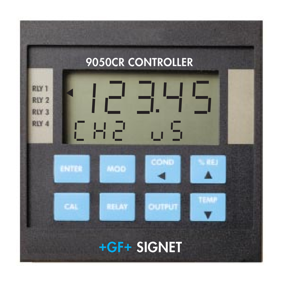
1.2 Front Panel Description 9050CR Controller RLY 1 RLY 2 RLY 3 RLY 4 COND % REJ ENTER TEMP RELAY OUTPUT + GF + SIGNET Item Function 1. Relay An- • Indicate activation status of control relays 1-4 (optional) nunciators: •... -
Page 9: Rear Panel Description
1.3 Rear Panel Description RLY3 RLY4 ANL2 SERIAL Tx GND Rx Note: 10 11 12 13 14 Rear terminals accept 18 to 22 AWG wire 1 5 1 6 1 7 1 8 1 9 2 0 2 1 2 2 2 3 2 4 2 5 2 6 2 7 2 8 + GND NO AC IN DC IN... -
Page 10: Sensor Selection And Installation
Chapter 2 2.1 Sensor Selection The 9050CR controller is compatable with + GF + SIGNET 3-28XX-1 series sensors. + GF + Signet Sensor Selection offers five sensor versions satisfying a wide range of measurement, listed below. and Installation For optimum sensor performance and life, the following requirements MUST be met: •... - Page 11 Resistivity measurements within the 10 MΩ to 18 MΩ (0.055 µS to 0.1 µS) range must be performed in solution temperatures from 20 °C to 100 °C. Dimensions: Order Fitting 3-2822-1 Sensor Number Cell Range Fitting Material 3-2822-1 10.0 100 - 100,000 µS 3/4 in.
-
Page 12: In-Line Sensor Installations
Dimensions Order Fitting 3-2823-1 Sensor Number Cell Range Fitting Material 3-2823-1 20.0 200 - 400,000 µS 3/4 in. 316 SS 15 ft./4.6 m cable (standard) Specifications Temperature Compensation: PT1000 8.0 in./ 203 mm Wetted materials: O-rings: Reversible Insulator: Teflon fitting assy for submersion Electrodes: 316 stainless steel... - Page 13 Oils or sediments in the system can coat or clog the sensor electrodes, causing poor response or no response at all. Mount the sensor in a location where the flow rate is moderate. Ideally, the sensor should be mounted where flow is directed into the sensor cavity (e.g.
-
Page 14: Submersible Sensor Installations
2.3 Submersible Sensor Installations + GF + SIGNET 3-2819-1, 3-2820-1, and 3-2821-1 sensors are easily modified for submers- ible installation. An extension pipe and female pipe union are required (customer supplied). 15 ft/4.6 m cable std. 100 ft/30 m max., Belden #9770 customer supplied... -
Page 15: Installation And Wiring
3.1 Mounting Instructions Chapter 3 The controller's 1/4 DIN enclosure is specifically designed for panel mounting. Adjustable mount- Installation ing brackets allow mounting in panels up to 1 in./ 25 mm thick. An adhesive template and instruc- and Wiring tions are included to insure proper installation. For outdoor and/or stand alone installations the splash-proof NEMA 4X/IP65 rear cover kit is recommended (ordered separately,... -
Page 16: Power Connections
3.2 Power Connections AC Power Connections AC Hot 90 to 132 VAC AC Ground* 180 to 264 VAC AC Neutral 1 5 1 6 1 7 1 8 1 9 2 0 2 1 2 2 2 3 2 4 2 5 2 6 2 7 2 8 Caution: Never connect live AC lines to the instrument. -
Page 17: Input Connections
3.3 Input Connections The 9050CR is compatible with + GF + SIGNET 3-28XX-1 series sensors. Wiring connections are identical for ALL sensor versions. Extended Cable Runs: Each sensor includes 15 ft/4.6 m of cable. Cable runs can extend up Caution: Remove instrument... -
Page 18: Output Relay Connections
One of three relay modes are selected for each relay (sec. 4.8). Relay contacts are rated at 5 A maximum. The 9050CR will accept one of each of the following cards: • 2-Relay Card: Provides two single pole double throw relays (sec. 5.4). -
Page 19: Verifying Analog Outputs
The Dual Proportional Relay Card provides a normally open (NO) contact for external device control. The main distinction from the 2-Relay card is the lack of the normally closed (NC) contact. Example: Device A IS NOT powered when relay 3 is off. Power is applied when relay 3's alarm setpoint is reached. -
Page 20: Analog Output Connections
1. Apply power to unit. Press: to view Option Record: ENTER available output options on the front panel display ANL 1= (unit displays "No Card" for unavailable options). _____________________ 2. Record option configurations for ANL 1 and ANL 2= ANL 2 in the spaces provided (left). This informa- _____________________ tion is necessary when wiring analog outputs. -
Page 21: System Configuration
4.1 Introduction Chapter 4 All functions which can be modified are contained in three menus: System The CAL menu contains those functions related to Configuration the sensor input signal and how it is interpreted by the instrument. The CAL menu also provides access to the display contrast and security code features. -
Page 22: Cal Menu Functions
OUTPUT Menu Functions RELAY Menu Functions • Analog output 1 control selection • Relay/channel control selection • Analog output 1 minimum setpoint • Relay mode: HI/LO, OR Pulse • Analog output 1 maximum setpoint • Analog output 1 minimum adjust (HI/LO Modes) (Pulse Mode) •... - Page 23 5. Channel 1 Temperature Compensation: The Channel 1 temperature compensation percentage: temperature compensation value keeps the process selectable from 0.00 to solution conductivity reading constant during 9.99%/ ° C temperature changes. All conductivity readings are based on 25 °C. A 2% conductivity change for each °C is common for many chemicals (factory default).
-
Page 24: Relay Menu Functions
9. Security Code Selection: Changes the 4-digit Security code selection: security code. When enabled, the security code 0000 to 9999 prevents unauthorized menu changes. The security function can be disabled by changing an internal dip switch setting (sec. 5.3). 4.3 RELAY Menu Functions 1. -
Page 25: Output Menu Functions
4. Relay 1 Hysteresis: Changes the relay 1 Relay 1 hysteresis: unlimited hysteresis value. Hysteresis values directly effect within selected range the LO and HI relay modes. Hysteresis is used to prevent relay "chatter", caused by the control value (e.g. conductivity) hovering around the relay's setpoint (sec. -
Page 26: Quick-Reference Keypad Sequence
5. Analog Output 1 Maximum Output Adjust: Analog output 1 maximum Allows the operator to adjust the maximum analog adjust: Adjustable for maximum accuracy. output level from the front keypad. An accurate digital voltage meter (DVM) is required for calibration. Functions 1-5 above repeat for analog output 2, when installed. - Page 27 6. Press: to view next item. RELAY OUTPUT 7. Repeat steps 4-6 of this procedure to modify each menu item. COND Exit menu by pressing: Cannot exit menu To exit or advance menu you must first while editing? to save changes OR press: press: ENTER COND...
-
Page 28: Cal Menu
4.6 CAL Menu The security function is not displayed when disabled Security Enter security ENTER Code? code using: (sec. 5.3). Press to select Displays shown are for Modify? ENTER sensor cell constant example only, actual displays may vary. Recall previous value Next menu item Menu access forces all Exit menu... - Page 29 Continued from previous page A known solution (sec. 5.6) See section is required for the "WET Modify? 4.7 procedure CAL" procedure (sec. 4.7). Next menu item Section 4.7 complete Exit menu COND Press to turn Modify? channel 2 on or ENTER With CH2 ON, menu steps Recall previous value...
-
Page 30: Wet Calibration Procedure
4.7 Wet Calibration Procedure Exit Wet Cal? Wet calibration is necessary for maximum system accuracy. This procedure is recommended for COND Press at any time "first-time" system start-up and for periodic sensor verification. A solution of known value (e.g. during steps 1-4 to exit wet buffer), a clean container, and an accurate °C cal procedure. -
Page 31: Relay Operation
to accept displayed value, OR Press ENTER Example enabled Press to enter known value as follows: for change Example % REJ TEMP COND A) Press to change displayed changed to buffer value value. Reset channel: enter zero to reset factory defaults, if B) Press then to cancel entry, OR... - Page 32 LO Relay LO/HI operation: When a relay is selected for Operation LO or HI operation, an individual setpoint and hysteresis value is entered for that relay. Control value • Relay Setpoint: Setpoints represent the control value at which the relay is energized. Setpoint units are displayed as µS, mS, ppm, kΩ, MΩ, °C, or % depending on the relay's assigned channel, range, and control selection (sec.
-
Page 33: Relay Menu
• Setpoint: Control value at which relay pulsing just begins. 120 max. Control value Setpoint Endpoint 120 max. Control value Endpoint Setpoint • Endpoint: Control value at which the relay pulse rate reaches the user set maximum value. • Pulse Rate: User set from 0 to 120 pulses per minute maximum. - Page 34 Continued from previous page Press Modify? enter relay setpoint ENTER value Recall previous value Next menu item RELAY Exit menu COND HI or LO mode selected step 2 Pulse mode Press to enter Modify? relay hysteresis ENTER selected value step 2 Recall previous value Repeat Menu? RELAY...
-
Page 35: Output Menu
4.10 OUTPUT Menu The security function is not displayed when disabled Security Enter security ENTER OUTPUT (sec. 5.2). Code? code using: 4 to 20/0 to 20 mA Press to choose Modify? ENTER output control isolated/non-isolated selection options illustrated for example only, actual Recall previous value Next menu item displays may vary. -
Page 36: View Only Menus
4.11 View Only Menus Three "view-only" menus are available any time during operation. Menu access does not affect the measurement in any way. Access the "view-only" menu of choice by pressing: RELAY OUTPUT Each menu item is displayed in the following order by successively pressing the corresponding menu key: CAL View-Only Menu... - Page 37 Function 6 only displays when 4. Relay 1 maximum pulse rate the proportional "pulse" relay selection: mode is selected. Functions 1-6 repeat for all installed relays. OUTPUT View-Only Menu 1. Analog output 1 control value 4 to 20 mA output option illustrated for example only, selection: actual displays may vary.
-
Page 38: Technical Support
Chapter 5 5.1 Accessing Internal Options 1. Remove bezel (1) by placing a coin in the notch (2), twist coin to remove the bezel from the Technical instrument casing, see Figure 2. Support 2. Loosen the four front bracket screws (3), then loosen the center "jack-screw"... -
Page 39: Ac Power Configurations
5.2 AC Power Configurations Two AC power options are possible; 90 to 132 VAC, or 180 to 264 VAC. Each power option is Figure 5 selectable via internal jumpers on the main pc Main pc board board (fig. 5). (top view) Option Sockets Security Feature OUTPUT CARD #1... -
Page 40: Installing Input/Output Options
5.4 Installing Input/Output Options Input/output option cards are "keyed" for proper insertion into four sockets. These sockets are clearly marked on the unit's main pc board. See Figure 5 (pg 33) and table below: Socket Labeled Compatible Options Input Card Dedicated for input option cards Output Card #1 Accepts all analog option cards, except the Dual... -
Page 41: Options And Accessories
5.6 Options and Accessories Part Number Input Cards Code 3-9050.400 Conductivity sensor input card 198 864 305 (isolated) Part Number Output Cards Code 3-9000.450-1 (Requires 4 to 20/0 to 20 mA (non-isolated) 198 864 631 configuration, sec. 5.5) 3-9000.450-2 0 to 5 VDC (non-isolated) 198 840 632 3-9000.450-3 0 to 10 VDC (non-isolated) - Page 42 Part Number Spare Parts Code 2400-0404 Front cover screws (4 each) 198 840 209 3-9000.570 Front cover gasket 198 840 210 Conductivity Solutions Premixed solutions are essential for proper calibration. Solutions are available from most instrumentation dealers. The following part number are listed for your reference.
-
Page 43: Parts Per Million Conversion Factor
5.7 Parts Per Million Conversion Factor The 9050CR is capable of displaying total dissolved solids (TDS) in parts per million (PPM) units. This is done by dividing the actual solution conductivity in µS by the programmed parts per million factor (PPMF). -
Page 44: Temperature Coefficient
Equipment Required • 9050CR controller with + GF + Signet sensor • Process solution samples (2) Procedure 1. Disable the temperature compensation factor by Sample Solution (Step 2) entering 0.00 (sec. - Page 45 Sample Solution (Step 3) 3. Cool the sample solution close to the minimum process temperature. Place sensor in the sample Displayed temperature: solution (allow several minutes for stabilization). T2 = _________________°C Record displayed temperature and conductivity values in the spaces provided (right). Displayed conductivity: A 10% change in conductivity between steps C2 = ___________________...
-
Page 46: Troubleshooting
5.9 Troubleshooting CAL/RELAY/OUTPUT Menu Messages Displayed Message Cause Solution 1. "...PPM FACTOR MUST Number entered Enter number between 1.00 and BE BETWEEN 1 outside range 3.00, factory default 2.00 (sec. 4.6) AND 3..." 2. "...MAX PULSE RATE Entered number Enter number between 1 and 120, MUST BE 120 OR too large factory default 120 (sec. - Page 47 Operational Messages Displayed Message Cause Solution 1. "_ _ _ _" A) Displayed A) Change to larger scale or shift reading too large display decimal to the right (sec. 4.6) (4-dashes) B) Temp. comp. % B) Verify temperature compensation selection too large. % setting for your process (sec.
- Page 48 Operational Messages Continued Diaplayed Message Cause Solution 6. "...OUT OF RANGE" A) Temp. improperly A) Check solution temp. and sensor entered or bad wiring (sec. 3.3) (Wet Cal Only, sensor B) Verify cell range (sec. 2.1), check sec. 4.7) B) Wrong sensor buffer value, verify scale selection cell or wrong buffer (sec.
-
Page 49: Specifications
Specifications General Data 0.055 µS to 400,000 µS Conductivity range: (2.5Ω to 18 MΩ ) Resistivity/conductivity measurements from 10 MΩ to 18 MΩ (0.055 µS to 0.1 µS) must be performed in solution temperatures from 20 °C to 100 °C. 0 to 100 °C Temperature range: Isolation:... - Page 50 Ambient Conditions 32 to 130 °F/0 to 55 °C Operating temp.: Relative humidity: 95% maximum, non-condensing Optional Cards 2-Relay Card Contacts: 2 SPDT outputs Rating: 5 A @ 250 VAC or 30 VDC maximum Dual Proportional Relay Card Contacts: 2 SPST outputs Rating: 5 A @ 250 VAC or 30 VDC maximum...
- Page 51 Limited Two-Year Warranty Warranty Signet Scientific Company warrants its instruments to be free from defects in material and workman- ship under normal use for a period of two years from the date of purchase by the initial owner, or three years from date of manufacture, whichever comes first, as described in the following para- graphs.
- Page 52 Signet Scientific Company shall have the sole right to determine whether in fact a warranty situation exists. Signet Scientific Company is continually making design changes and improvements that adapt to the original circuit configuration. These will be incorporated as required in older units on a minimal charge basis while under warranty.
- Page 53 NOTES:...
- Page 54 NOTES:...
- Page 55 NOTES:...
- Page 57 + GF + SIGNET Signet Scientific Company, 3401 Aerojet Avenue, El Monte, CA 91731-2882/U.S.A., Phone (818) 571-2770, Fax (818) 573-2057 Representative Offices U.S.A. George Fischer, Inc., 2882 Dow Avenue, Tustin, CA 92680-7285/U.S.A., Toll Free Phone (800) 854-4090, Fax (714) 731-6201 Georg Fischer Rohrleitungssysteme AG, CH-8201 Schaffhausen/Schweiz, Tel.
Need help?
Do you have a question about the 9050CR and is the answer not in the manual?
Questions and answers