Table of Contents
Advertisement
Signet 8900 Multi-Parameter Controller
3-8900.090-1
3-8900.090-1
Rev. H 03/10
Contents
6.2 Digital (S
3
Important Safety Information
•
Read and understand instruction manual before using
this product.
•
This unit is designed to be connected to equipment
which can be hazardous to persons and property if
used incorrectly. Read and understand all associated
equipment manuals and safety warnings before using
with this product.
•
Do not remove rear panel slot shields if the modules
are not installed.
English
2
4
4
5
6
6
6
6
7
7
8
8
9
10
10
11
12
12
13
14
15
17
17
18
18
19
19
20
20
21
21
22
22
22
23
23
24
9.8 Channel Settings: OTHER (4-20)
•
Remove power to unit before wiring input and output
connections.
•
Wiring connections to this product should only be
performed by qualifi ed personnel.
•
Do not exceed published specifi cations in the use of
this product.
•
In case of communication error or loss of source
signal:
• Relays will be deactivated.
• Current outputs will go to 22.1 mA.
• Voltage outputs will go to 0 V.
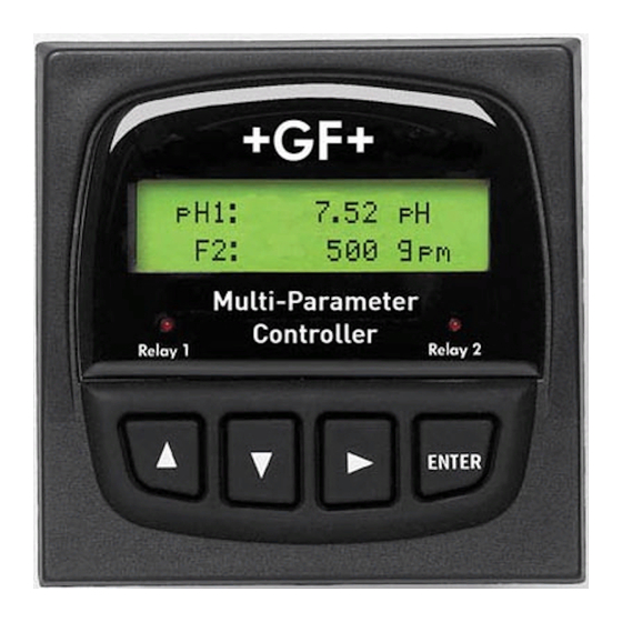
C1
2.50 µS/cm
F2
58.43 GPM
Multi-Parameter
Controller
Relay 1
Relay 2
ENTER
24
25
25
26
27
27
28
30
30
31
33
34
35
36
36
37
37
38
38
38
38
39
39
40
41
43
44
L)
45
3
47
48
52
Advertisement
Table of Contents

Related Manuals for GF Signet 8900


Summary of Contents for GF Signet 8900
-
Page 1: Table Of Contents
Signet 8900 Multi-Parameter Controller 2.50 µS/cm 58.43 GPM 3-8900.090-1 Multi-Parameter Controller 3-8900.090-1 Rev. H 03/10 English Relay 1 Relay 2 ENTER Contents 1. Specifi cations 9.1 Channel Settings: Flow 9.2 Channel Settings: pH 9.3 Channel Settings: ORP 2. Description 9.4 Channel Settings: Conductivity 2.1 Compatibility... -
Page 2: Specifi Cations
IMPORTANT SAFETY INFORMATION AC ONLY DC ONLY For additional operator safety, an adhesive power indication label (AC ONLY or DC ONLY) is packaged with each Power Module and should be applied to the 8900 rear panel as illustrated. Signet 8900 Multi-Parameter... - Page 3 Modes of operation: Internal Relays: Off, Low, High, Window, Vol. Pulse, Prop. Pulse, Pulse Width Modulation, Total Volume, USP, Advanced External relays: Off, Low, High, Window, USP Total Volume, Advanced Hysteresis: User adjustable Time Delay: 0 to 6400 seconds Signet 8900 Multi-Parameter...
-
Page 4: Description
2. Description The 8900 Multi-Parameter Controller takes the concept of modularity to the extreme. Two base units, one with back-lit LCD and the other with vacuum fl uorescent display can be confi gured by the user in the fi eld. -
Page 5: System Overview
2.2 System Overview The most basic 8900 system consists of a Base Unit, an I/O Module and a Power Module. Outputs and relays are optional. Each item is ordered separately. See Section 3 Installation & Basic Functionality, and Ordering Information for more details. -
Page 6: Installation And Basic Functionality
• If the 8900 Base Unit will be mounted in a panel, plug-in modules may be installed either before or after the base unit is mounted. If the 8900 Base Unit will be mounted using the accessory Wall Mount Bracket, fi rst install plug-in modules. -
Page 7: I/O Module
Optional analog outputs are contained on the I/O Module, and will always Analog Output 1 be identifi ed as Outputs 1 & 2 in the 8900 menus. Any and all analog (if applicable) outputs are freely assignable to any channel. All analog outputs available... -
Page 8: Output Module
• The analog outputs obtained via these separate modules will always be identifi ed as Outputs 3 & 4 in the 8900 menus. The slot on the rear panel is labeled accordingly. • It is perfectly acceptable to mix and match analog output types between those contained on the I/O Module and those obtained via these separate modules. -
Page 9: 8059 External Relay Module
OUTPUT 24VDC 8059-2AC • The 8900 will support up to eight (8) relays, though only four actually fi t directly inside its compact DIN enclosure. 8059 External Relay Modules of either two or four relays may be connected to the 8900 via digital (S L) at the I/O Module (this does NOT consume a sensor input channel). -
Page 10: Mounting The Base Unit
5. Mounting the Base Unit Quick-clip mounting The 8900 may be mounted in a panel, on a wall, or on virtually 96 mm/3.78 in. bracket any surface including shelves, racks and pipes. All methods of mounting the 8900 make use of the Signet Quick-clip for holding the instrument securely in place. -
Page 11: Mounting Accessories
Description 3-0000.596-1 ¼-DIN wall mount bracket, 6.5 in. depth • Use to mount the 8900 (without a splashproof rear cover) to a solid wall or bulkhead. • Powder coated aluminum, black, 3.2 mm (0.125 in.) thick 3-0000.596-2 ¼-DIN wall mount bracket, 9.0 in. depth •... -
Page 12: Wiring
All of the sensors in the table below are compatible with the 8900. The three models limited to 60 m (200 ft) are self-powered sensors. The 8900 automatically provides power to the others via the I/O Module (normal sensor wiring). - Page 13 • Select Passive analog output cards instead of Active. • Select the DC power supply card instead of the AC card. Any one of these measures will insure that the 8900 has suffi cient power available to support up to six 2551 Magmeters. How to Wire Digital (S L) Sensors Tie all red wires together.
-
Page 14: Digital Cable Length Calculations
38 mA ** The digital (S L) communication link between the 8900 and the 8059 is powered by the 8900 and consumes 1 mA maximum. However, the 8059 External Relay Module always requires a separate power source for its operation. -
Page 15: Digital Cable Routing Diagrams
6.2.2 Digital Cable Routing Diagrams 3-8900.621C I/O Module 3-8900.401-X +5VDC (Black) Frequency Input Freq. Input (Red) GND (Shield) +5VDC (Black) Frequency Input 2 Freq. Input 2 (Red) If two digital (S L) sensors are wired separately, the cable S 3 L... - Page 16 This diagram shows fi ve digital (S L) sensors. A fl ow sensor with a frequency output can be added to terminals 1-2-3 to complete the system. S 3 L Sensor 3-8900.621C I/O Module 3-8900.401-X +5VDC (Black) Frequency Input Freq. Input (Red) GND (Shield)
-
Page 17: Power Module (3-8900.402-X)
6.3 Power Module (3-8900.402-X) • The 8900 can operate from a Universal AC power input (3-8900.402-1) or from a 24 VDC power input (3-8900.402-2) • For safety, place the AC ONLY or DC ONLY decal on the rear panel of the 8900. -
Page 18: Relay Module (3-8900.403-X)
6.5 Relay Module (3-8900.403-X) The alarm is OFF during normal operation, and will go ON according to 8900 Relay settings. Solid State Relays (non-mechanical switches) Normally open/closed operation: Software selectable AC or DC Max. pulse rate: 600 pulses per minute power (volumetric pulse &... -
Page 19: Operational Overview
"_" Function 7.1 General Operation Flowchart The four display modes of the 8900 are layered as shown in the fl owchart below. Keypad symbols illustrate basic navigation within and between these modes. • View: View mode is normal operation for the 8900. After system setup is completed, all measurement values for each channel, plus the status of any analog outputs and relays will be available. -
Page 20: System Confi Guration
The Menu Directory may also be reached from any item in View by pressing and holding the ENTER button for two seconds. • The Menu Directory provides access to the seven separate menus of the 8900: System Setup, Channel Settings, Hold Inputs, Relay, Output, Calibration, and Options. -
Page 21: System Setup Menu
8. System Setup Menu All of the basic system setup functions are automated in the 8900, with the exception of Channel Type assignments. These must be done by the user. After Channel types are assigned, the 8900 will automatically complete all of the remaining tasks in the System Setup menu. -
Page 22: Automatic Sensor Recognition
L) bus. 8.3 Automatic Channel Assignment: After a channel type is assigned (section 8.1), the 8900 compares the sensor identifi cation list with each channel type and assigns a sensor to each channel, following a specifi c heirarchy: All Channels: Native sensors (sensors of the same measurement type as the channel type) will be assigned fi rst. -
Page 23: Other Automatic Displays
These assignments are made in Function Type of the Options menu. • The 8900 allows up to four derived functions to be used for display and control at any one time. An example of the display for derived functions is shown here. This format cannot be modifi ed. -
Page 24: Channel Settings
Lock Off: No EDIT code required to reset the Resettable totalizer to zero. Lock Off > Dampens display, output and relay response rates for this channel. F1 Average: Off: Near instantaneous updates > Low: 4 s Med: 8 s Hi: 32 s Signet 8900 Multi-Parameter... -
Page 25: Channel Settings: Ph
-1000 mV > setpoints. 20mA Set Point 1 1000 mV > Dampens display, output and relay response rates for this channel. ORP1 Average: Off: Near instantaneous updates > Low: 4 s Med: 8 s Hi: 32 s Signet 8900 Multi-Parameter... -
Page 26: Channel Settings: Conductivity
Select decimal location for the temperature display associated with this conductivity sensor. T1 Decimal: XXXXX. XXXX.X XXX.XX ****.* > Dampens display, output and relay response rates for this channel. C1 Average: Off: Near instantaneous updates > Low: 4 second averaging; Med: 8 second averaging; Hi: 32 second averaging. Signet 8900 Multi-Parameter... -
Page 27: Channel Settings: Pressure
If this Channel is TEMPERATURE and the sensor is 4 to 20 mA, set the minimum and maximum setpoints. 20mA Set Point 1 100.00 °C > Dampens display, output and relay response rates for this channel. T1 Average: Off: Near instantaneous updates Low: 4 s Med: 8 s Hi: 32 s > Signet 8900 Multi-Parameter... -
Page 28: Channel Settings: Level
If a pressure sensor is used for Level measurement, enter the specifi c gravity of the fl uid. 1.0000 > V1 Shape: Select the shape of the vessel where the level sensor is located. Vert Cylinder > Vert Cylinder Horiz Cylinder Rectangular Custom Signet 8900 Multi-Parameter... - Page 29 Select the decimal location for the Volume display. Must be consistent with the range: XXXXX. XXXX.X XXX.XX XX.XXX X.XXXX **.*** > Dampens display, output and relay response rates for this channel. L1 Average: Off: Near instantaneous updates Low: 4 s Med: 8 s Hi: 32 s > Signet 8900 Multi-Parameter...
-
Page 30: Hold Inputs
9.8 Channel Settings: If Channel Type = OTHER (4–20) • The 8058 Signal Converter allows any 4 to 20 mA signal to serve as an input signal to the 8900. • For example, a Dissolved Oxygen sensor with a 4 to 20 mA output might be connected to the 8900. -
Page 31: Relay Mode Descriptions
11. Relay Mode Descriptions The 8900 offers a wide selection of relay operating modes that enable the user to create complex control scenarios. Internal relays (those installed on the two Relay modules) can be confi gured for all of the available modes. - Page 32 Proportional Pulse mode varies the frequency of pulses in direct 100 pulses proportion to minimum and maximum setpoints. • The 8900 does not allow use of this mode for Pressure applications. Example: • The output will be 0 pulses/min. at process values less than 5.0.
-
Page 33: Relay Setup Menu
If Relay mode is pulse: Set the duration of the relay pulse. Minimum 0.1 s, maximum 999.9 s (16.66 minutes) For solid state relays only: N.C. = Normally Closed N.O. = Normally Open Manually toggle relay to test operation. Signet 8900 Multi-Parameter... -
Page 34: Advanced Relay Mode
When all relay parameters are set, press the UP and DOWN keys together to exit from the Relay menu back to the Menu Directory, then press the same keys again to exit from the Menu Directory back to normal operation. Signet 8900 Multi-Parameter... -
Page 35: Output
If 4 to 20 mA, test limits are 3.8 mA to 21.0 mA. If 0 to 5 VDC, test limits are 0.00 to 5.50 VDC. > If 0 to 10 VDC, test limits are 0.00 to 10.50 VDC. Signet 8900 Multi-Parameter... -
Page 36: Calibration
Select VOLUMETRIC CALIBRATION if the fl ow rate can be Select RATE CALIBRATION to match the dynamic fl ow rate to determined by fi lling a vessel of known volume. The 8900 will an external reference. Entering a rate will modify the existing count the number of pulses generated as the known volume of K-Factor. -
Page 37: Calibration: Orp
13.2 Calibration: If Channel type = pH SENSOR: Select to perform calibration at the sensor via 2750 EasyCal. pH1 Cal at: INSTRUMENT: Select to perform calibration at the 8900 via the steps below. Sensor > If Cal at Instrument is selected, the following menu items appear: Place sensor in any pH buffer. -
Page 38: Calibration: Conductivity
13.4 Calibration: If Channel type = Conductivity SENSOR: Select to perform calibration at the sensor via 2850 EasyCal. C1 Cal at: INSTRUMENT: Select to perform calibration at the 8900 via the steps below. Sensor > If Cal at Instrument is selected, the following menu items appear: Set Conductivity Place sensor in any conductivity test solution. -
Page 39: Options
Password Security The standard password is the UP-UP-UP-DOWN keys, pressed in sequence. This access code is designed to protect the 8900 from unintentional changes. It is best suited for systems where a group of people need to be able to change settings. -
Page 40: Appendix A: Derived Functions
Appendix A: Derived Functions When two or more measurements of the same type are present, the 8900 can calculate several derived functions from like pairs. Up to three derived Functions can be defi ned and used as the source for display and output functions. -
Page 41: Appendix B: Level System Confi Guration
The point in the vessel where you want the 8900 to display zero (0 ft, 0 gal. etc). • If Z is located below the fl uid surface, the 8900 will display a positive level measurement. • If Z is located above the fl uid surface, the 8900 will display a negative level measurement. - Page 42 Simpler sections require fewer defi ning points. Note that the The 8900 performs linear interpolation between adjacent points. cylinder requires only custom points 9 and 10. Technical Reference for Level measurement Level, volume and mass calculations performed by the 8900 include: Volume calculations Pressure to level conversion: Vertical cylinder: V = •...
-
Page 43: Appendix C: Conductivity & Temp Comp
1 PPB is equivalent to 1 μg per liter. (150 x (48 - 25)) - (205 x (23 - 25)) 3860 • The 8900 calculates PPM or PPB by dividing the μS value by a TDS Factor that you defi ne. •... -
Page 44: Appendix D: Usp Limits
Using the USP function USP setpoints are defi ned as a percentage below the USP limit, so a USP alarm is always a HIGH alarm. The 8900 can be set to warn you if the conductivity approaches within a set percentage of the USP limit. -
Page 45: Appendix E: Cloning Using Digital
Step 1: Controller Designations Frequency Input 2 Freq. Input 2 (Red) S 3 L S L (Red) Designate the 8900 controller that will receive the data and Input GND (White/Shield) refer to this controller as the Receiving Controller. +5VDC (Black) S 3 L... - Page 46 Controller’s display. Error: No Data From Host > In either case, press the right arrow key and both 8900 controllers will restart and the Receiving controller confi guration settings will be adopted if the cloning operation was successful. Signet 8900 Multi-Parameter...
-
Page 47: Appendix F: Btu Quick Start Guide
Appendix F: BTU Quick Start Guide This guide outlines how to confi gure the 8900 Multi-Parameter to calculate Power and Energy. There are some limitations that must be known and requirements that must be adhered to in order for the calculation to work properly. -
Page 48: Appendix G: 8900 Display Messages
Appendix G: 8900 display messages The 8900 communicates with the user to notify when something is wrong, and to inform of tasks underway. This appendix lists all of the messages that may appear during operation, and describes the purpose of the message. - Page 49 Value Must Be Self explanatory. If a relay is in Proportional Pulse Complete 1 Or Higher mode, the mimimum pulse rate is 1, the maximum rate is 400. 8900 Value Must Be Self explanatory. Restarting 400 Or Less Signet 8900 Multi-Parameter...
- Page 50 Notes Signet 8900 Multi-Parameter...
- Page 51 Notes Signet 8900 Multi-Parameter...
-
Page 52: Ordering Information
For Worldwide Sales and Service, visit our website: www.gfsignet.com • Or call (in the U.S.): (800) 854-4090 For the most up-to-date information, please refer to our website at www.gfsignet.com 3-8900.090-1 Rev. H 03/10 English © Georg Fischer Signet LLC 2010...
Need help?
Do you have a question about the 8900 and is the answer not in the manual?
Questions and answers