ACTi A950 Hardware Manual
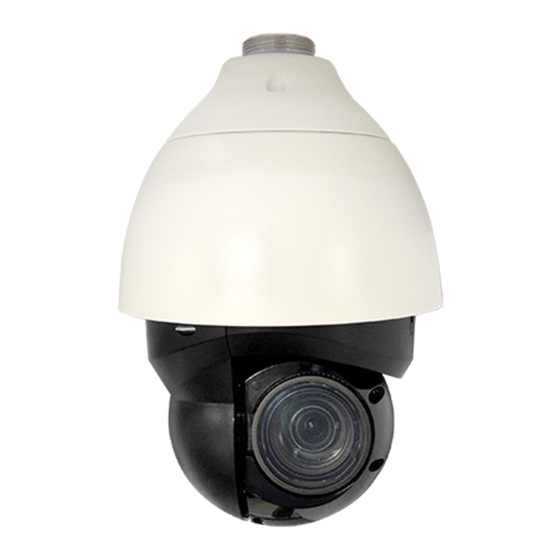
Outdoor speed dome
Hide thumbs
Also See for A950:
- Quick installation manual (2 pages) ,
- Firmware manual (116 pages) ,
- Firmware manual (115 pages)
Table of Contents
Advertisement
Quick Links
Advertisement
Table of Contents

Subscribe to Our Youtube Channel
Related Manuals for ACTi A950


Summary of Contents for ACTi A950
- Page 1 Outdoor Speed Dome Hardware Manual A950 2018/12/20...
-
Page 2: Table Of Contents
Use the Safety Strap ................13 Mount the Camera ................... 14 Cable Connections ..........17 Power Connection ................... 18 DC12V ....................18 AC24V....................19 Ethernet Cable Connection ..............19 Audio, Digital Input / Output and Serial Connection ......20 Accessing the Camera ......... 21 www.acti.com... - Page 3 Hardware Manual Configure the IP Addresses ..............21 Access the Camera .................. 24 www.acti.com...
-
Page 4: Precautions
Every reasonable care has been taken during the writing of this manual. Please inform your local office if you find any inaccuracies or omissions. We cannot be held responsible for any typographical or technical errors and reserve the right to make changes to the product and manuals without prior notice. www.acti.com... - Page 5 This product has been tested and found to comply with the limits for Class B Information Technology Equipment according to European Standard EN 55022 and EN 55024. In a domestic environment, this product may cause radio interference in which cause the user may be required to take adequate measures. www.acti.com...
-
Page 6: Safety Instructions
Safety Check Upon completion of any service or repairs to this video product, ask the service technician to perform safety checks to determine if the video product is in proper operating condition. www.acti.com... -
Page 7: Introduction
Hardware Manual Introduction List of Models This hardware manual contains the following model: 8MP Outdoor Speed Dome with D/N, Adaptive IR, Extreme WDR, ELLS, A950 22x Zoom Lens www.acti.com... -
Page 8: Package Contents
Terminal Blocks (x3) Screw Warranty Card QIG & Warranty Card NOTE: The above pictures are for reference only; actual items may slightly vary. * Depending on territory, the package may come with a power adapter or a PoE Injector. www.acti.com... -
Page 9: Physical Description
19 for terminal block mapping. Reset Button The reset button is used to restore the camera factory default settings. Using a tool, press and hold for at least 20 seconds to reset. *Please contact the manufacturer for compatible PoE injector. www.acti.com... - Page 10 NOTE: It is not recommended to record with the SD card for 24/7 continuously, as it may not be able to support long term continuous data read/write. Please contact the manufacturer of the SD card for information regarding the reliability and the life expectancy. www.acti.com...
-
Page 11: Mounting Options
Mounting Options There are several mounting options that you can use to install the camera. Below are some examples. For more information about mounting solutions and accessories, please visit our website (http://www.acti.com/mountingselector). Mount Types Accessories Pendant Suitable when mounting the Outdoor PTZ on a hard ceiling. -
Page 12: Before Installation
1. Locate the memory card slot on the side of the lens module. Loosen the two (2) screws to open the cover. 2. Insert the micro SD card into a micro SD card adapter. Then, insert the card into the slot with the metal contacts facing up the camera. Push the card until it clicks into place. www.acti.com... -
Page 13: Installation Procedures
Below are the basic installation procedures when mounting the camera with PMAX-0324 Wall Mount with access behind the wall. For detailed information and other mounting solutions, check the website (http://www.acti.com/mountingselector). NOTE: The following pictures are for reference only, actual camera and cable connections may slightly vary. -
Page 14: Mount The Camera
Align the screw holes on the pendant mount with the drilled holes and fix the pendant mount to the wall with four screws. STEP 3 Coat the PTFE thread seal tape (not supplied) to the thread of mounting kit around five times for waterproof purpose as Fig. 5. (Fig.5) www.acti.com... - Page 15 I/O and audio I/O connections, please see for pin definition. Cable Connections (Fig.8) STEP 6 Slightly pull the anti-drop chain and other cables into the pendant tube. Then screw the mounting plate back to the mini pendant mount. (Fig.9) (Fig.10) www.acti.com...
- Page 16 Hardware Manual STEP 7 Fix the camera to the mounting kit with the supplied screw and washers. (Fig.11) Installation completed. (Fig.12) www.acti.com...
-
Page 17: Cable Connections
While running cables, slightly bend the cables to a U-shaped curve to make a low point (as demonstrated in the figures below). The purpose is to prevent water from entering the camera along the cables from above. www.acti.com... -
Page 18: Power Connection
When users connect DC12V power jack and the RJ-45 port at the same time, the power input comes from the DC12V connector. If the DC12V power source fails, the camera will switch power input seamlessly to the RJ-45 port until the DC12V power source is restored. www.acti.com... -
Page 19: Ac24V
PC. NOTE: Check the status of the link indicator and activity indicator LEDs. If the LEDs are unlit, please check the LAN connection. Green Link Light indicates good network connection. Orange Activity Light flashes for network activity indication. www.acti.com... -
Page 20: Audio, Digital Input / Output And Serial Connection
GND (Alarm Audio Out Alarm Out B1 Alarm In 4 I/O & RS-485) Alarm Out B2 Alarm In 3 Audio In (Audio I/O) Alarm Out A1 RS-485 D+ Alarm In 2 Alarm Out A2 RS-485 D- Alarm In 1 Definition www.acti.com... -
Page 21: Accessing The Camera
Windows system – just by pressing the “Network” icon, all the cameras of the local area network will be discovered by Windows, thanks to the UPnP function support of our cameras. In the example below, the camera model that has just been connected to the network is successfully found. www.acti.com... - Page 22 Hardware Manual Double-click the mouse on the camera model name, the default browser of the PC is automatically launched and the IP address of the target camera is already filled in the address bar of the browser. www.acti.com...
- Page 23 PC has to be configured to match the network segment of the camera. Manually adjust the IP address of the PC In the following example, based on Windows 7, we will configure the IP address to 192.168.0.99 and set Subnet Mask to 255.255.255.0 by using the steps below: www.acti.com...
-
Page 24: Access The Camera
80, which can be omitted from the address for convenience. Before logging in, you need to know the factory default Account and Password of the camera. Account: Admin Password: 123456 For further operations, please refer to the Firmware User’s Manual. www.acti.com... - Page 25 Copyright © 2018, ACTi Corporation All Rights Reserved 7F, No. 1, Alley 20, Lane 407, Sec. 2, Ti-Ding Blvd., Neihu District, Taipei, Taiwan 114, R.O.C. TEL : +886-2-2656-2588 FAX : +886-2-2656-2599 Email: sales@acti.com...
Need help?
Do you have a question about the A950 and is the answer not in the manual?
Questions and answers