Table of Contents
Advertisement
Advertisement
Table of Contents

Related Manuals for Autogrow MultiGrow


Summary of Contents for Autogrow MultiGrow
- Page 1 MultiGrow Installation Guide...
-
Page 2: Table Of Contents
Bus Addressing ....................................5 Bus Terminators ....................................6 Module Connections ........................7 General ......................................7 MultiGrow Controller ..................................7 Output Modules (Paired & Single) ..............................10 EpMT Remote Sensors Module ..............................13 Environment Sensor Module ................................. 14 Temperature Transmitter Module ..............................15 Weather Station &... -
Page 3: Introduction
Power Supplies Within the MultiGrow Controller, the PC and multi USB board are supplied by a 12V DC regulated power supply. Only the adapter supplied with the controller should be used however if it requires replacing, please contact Autogrow for a replacement. -
Page 4: Bus Network
MultiGrow Installation Guide It is recommended to supply power to the MultiGrow controller through a UPS, this will ensure no unnecessary shutdowns due to power fluctuations. It is also a good idea to power the internet router through the same UPS. -
Page 5: Bus Addressing
16 addresses for each module type. This will allow for 32 modules of the same type on the Bus Network. Up to a total of 128 Autogrow modules can be connected onto a single bus network. V2.0 MultiGrow Installation Guide... -
Page 6: Bus Terminators
Note: If a switch is left closed in the middle of the bus it will seriously degrade the communications which may then work intermittently or not at all. V2.0 MultiGrow Installation Guide Copyright© 2018 Autogrow Systems Ltd... -
Page 7: Module Connections
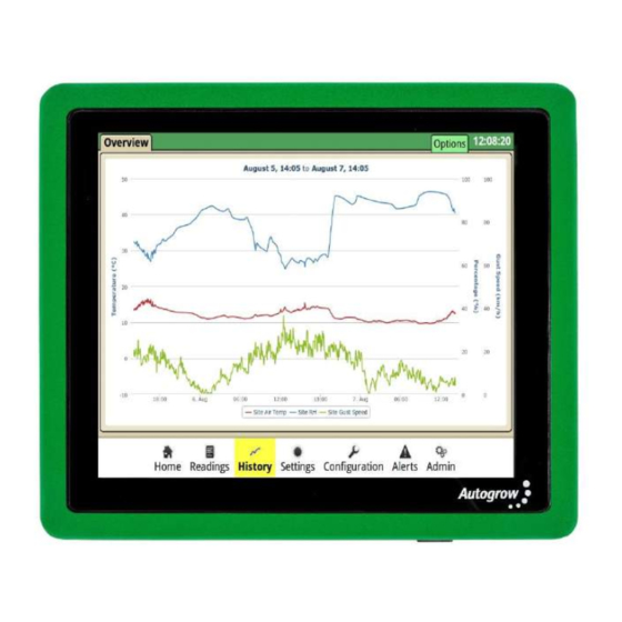
Module Connections General The MultiGrow Controller should be installed in a position well away from water splashes or mist/vapour. Preferably outside the greenhouse if you intend to operate at high humidity. It should be mounted in a cool, dry place out of direct sunlight or even inside an electrical panel. - Page 8 MultiGrow Installation Guide The Autogrow 17” touch screen can be connected to the controller via the supplied HDMI and USB cables however a standard computer monitor, with HDMI or Display port connectors can be connected. Connections are on the PC within the MultiGrow Controller, in addition a keyboard and mouse should be connected to the USB ports.
- Page 9 MultiGrow Installation Guide The diagram below shows the Bus Network connections on the Multi USB board, the wiring diagram is also available in the Appendix. V2.0 MultiGrow Installation Guide Copyright© 2018 Autogrow Systems Ltd...
-
Page 10: Output Modules (Paired & Single)
24v DC. Ensure the Power Switch is selected to “Plug Pack” in all cases. V2.0 MultiGrow Installation Guide Copyright© 2018 Autogrow Systems Ltd... - Page 11 MultiGrow Installation Guide The diagram below shows the Bus Network and Output connections for both types of Output Modules, the wiring diagrams are also available in the Appendix. V2.0 MultiGrow Installation Guide Copyright© 2018 Autogrow Systems Ltd...
- Page 12 The COMMON connection is common across ALL connectors including the Power Connectors –ve input. This means that the COMMON & -ve are inextricably linked and appropriate measures must be taken when wiring the outputs to mains switch panels. V2.0 MultiGrow Installation Guide Copyright© 2018 Autogrow Systems Ltd...
-
Page 13: Epmt Remote Sensors Module
If using a GS3 Moisture probe as apposed to an EC5 then the GS3 dip switch must be selected on the EpMT Module PCB board. V2.0 MultiGrow Installation Guide Copyright© 2018 Autogrow Systems Ltd... -
Page 14: Environment Sensor Module
There are two methods of mounting and installing the Environment Sensor Module, details are included in the Appendix. The diagram below shows the Bus Network connections on the Environment Sensor Module, wiring diagrams are also available in the Appendix. V2.0 MultiGrow Installation Guide Copyright© 2018 Autogrow Systems Ltd... -
Page 15: Temperature Transmitter Module
This function can be used for measuring temperature on hydronic heating, soil temperature, nutrient temperature, etc. The diagram below shows the connections on the Temperature Transmitter Module, the wiring diagrams are also available in the Appendix. V2.0 MultiGrow Installation Guide Copyright© 2018 Autogrow Systems Ltd... -
Page 16: Weather Station & Sensors
Ensure it is fully inserted and then screw down the lid after checking the gasket is in good condition to ensure water tightness. V2.0 MultiGrow Installation Guide Copyright© 2018 Autogrow Systems Ltd... -
Page 17: Testing And Troubleshooting
Once all the field wiring has been proven to operate, the MultiGrow Controller can be brought into service. After switching it on you will need to log in, use password 44. Once successfully logged in navigate to Configuration >... -
Page 18: Common Faults
When the fault has been fixed, the heartbeat light will flash green. If you are having difficulty with a fault or if the fault you are experiencing is not listed above, please contact Autogrow and we may be able to help by remotely logging in to the controller. -
Page 19: Appendix
Environment Sensor Mounting Guide Temperature Transmitter Module Bus Network & Sensor Connections Weather Station Module Bus Network & Sensors Connections Weather Station Mast Mounting Recommendations Bus Details Fillable Form Output Module Details Fillable Form V2.0 MultiGrow Installation Guide Copyright© 2018 Autogrow Systems Ltd... -
Page 20: Notes
MultiGrow Installation Guide Notes: V2.0 MultiGrow Installation Guide Copyright© 2018 Autogrow Systems Ltd...
Need help?
Do you have a question about the MultiGrow and is the answer not in the manual?
Questions and answers