Advertisement
Quick Links
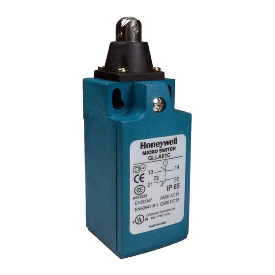
Installation Instructions for the
MICRO SWITCH GLL Series Limit Switch
m
WARNING
PERSONAL INJURY
• Where possible, install these switches with the conduit
opening pointed down to drain moisture away from switch.
• Do not install switch at the low point of a conduit run.
• Install a fitting into the conduit opening that provides
strain relief to the wires/cable, as well as sealing against
contaminants found in the application.
• In applications where fluids or moisture may be present,
seal the fitting threads with a product such as Teflon tape
or pipe dope.
Failure to comply with these instructions could result in
death or serious injury.
GENERAL INFORMATION
1.
Refer to page 2 for specifications.
2.
Rotate switch head to desired position (90° increments).
Review adjusting instructions below.
3.
Mount switch using two M4 or #8 screws (not included).
Torque screws to mounting surface 4,9 N m to 5,9 N m
[43.4 in lb to 52.2 in lb].
4.
All normally closed (NC) contacts are direct opening
ADJUSTMENT INSTRUCTIONS
To give flexibility in application, the user can perform the
adjustments described below in any order before wiring the
unit.
ACTUATOR HEAD POSITIONING
The actuator head may be positioned in any of four directions.
1.
Remove the four head retaining screws while holding
actuator head in place.
2.
To prevent actuator spring loss, remove head slowly to
relieve spring tension prior to removal.
3.
Rotate actuator head to desired position.
4.
Position the large diameter end of the actuator spring
over the actuator. Place retaining screws through gasket
material and position head over screw holes in desired
position.
5.
Securely tighten the screws to 0,2 N m [1.7 in lb] of torque.
Sensing and Internet of Things
POSITIONING LEVER
The lever on rotary actuated units is adjustable to any of the
segmented positions 360° around the shaft; however, the
degree of rotation is dependant on head position and direction
of roller.
1.
Loosen the lever retaining screw with a Phillips head
screwdriver.
2.
Remove lever.
3.
Reposition lever to desired location.
4.
Securely tighten screw.
REVERSING THE ROLLER LEVER
The roller arm may be reversed to face the roller to the inside or
outside of the arm.
ADJUSTABLE LENGTH LEVERS
1.
Loosen the lever's adjustment screw using a Phillips head
screwdriver.
2.
Adjust to desired length.
3.
Securely tighten adjustment screw to 1.0 N m [8.85 in lb] of
torque.
.
TOP ROLLER PLUNGER
Switches with top roller plunger must be mounted with plunger
in desired position. Actuating device must not exceed over
travel distance.
WIRING
1.
Remove front cover plate screw.
2.
Contact block area by terminal screw is labeled for NO
(Normally Open) and NC (Normally Closed) contacts.
3.
Connect stranded wire (0,75 mm² - 2,5 mm², 18 AWG-14
AWG) or solid wire (0,75 mm² - 1,5 mm², 18 AWG-16 AWG)
to desired connector terminals. Use 90 °C [194 °F] rated
wire when ambient temperature is to exceed 75 °C [158 °F]:
•
Torque switch terminal screws to 0,8 N m to 1,0 N m
[7.1 in lb to 8.9 in lb]
4.
Securely tighten cover screw to 0,5 N m [4.4 in lb] of torque.
Issue 5
50012101
Advertisement

Related Manuals for Honeywell MICRO SWITCH GLL Series


Summary of Contents for Honeywell MICRO SWITCH GLL Series
- Page 1 Installation Instructions for the MICRO SWITCH GLL Series Limit Switch Issue 5 50012101 POSITIONING LEVER WARNING The lever on rotary actuated units is adjustable to any of the PERSONAL INJURY segmented positions 360° around the shaft; however, the • Where possible, install these switches with the conduit degree of rotation is dependant on head position and direction opening pointed down to drain moisture away from switch.
-
Page 2: Specifications
Snap Action (Break Before Make) (Make Before Break) Slow Action 1NO/1NC 1NO/1NC 1NO/1NC Slow Action Slow Action Snap Action (Break Before Make) (Make Before Break) Slow Action 1NO/1NC 1NO/1NC 1NO/1NC 5Ncm 8Ncm 12Ncm 8Ncm 5Ncm 8Ncm 12Ncm 8Ncm 2 sensing.honeywell.com... - Page 3 GLL Series 50012101 ISSUE 5 Figure 3. GLLA**D, GLLC**D Dimensions and Figure 4. GLLA**F, GLLC**F Dimensions and Bar Charts Bar Charts [0.95] [0.83] [1.22] 5 [0.197] [0.71] [0.4] 15 [0.60] [0.39] Ø 4,2 [0.87] [0.165] [1.22] Ø4,2 [0.165] 11,5 [0.45] 40,5 [1.59] [0.31]...
- Page 4 (Make Before Break) Slow Action Conduit thread [0.63] 1NO/1NC 1NO/1NC 1NO/1NC [0.87] [1.22] 30,5 [1.20] Slow Action Slow Action Snap Action (Break Before Make) (Make Before Break) Slow Action 1NO/1NC 1NO/1NC 1NO/1NC 5Ncm 8Ncm 12Ncm 8Ncm 5Ncm 8Ncm 12Ncm 8Ncm 4 sensing.honeywell.com...
- Page 5 GLL Series 50012101 ISSUE 5 Figure 7. GLLA**A1Y, GLLC**A1Y Dimensions Figure 8. GLLA**A2Y, GLLC**A2Y and Bar Charts Dimensions and Bar Charts 42,5 [1.67] Ø 50 [1.96] [0.4] 42,5 Ø 50 [1.67] [1.96] [0.39] Buna Buna rubber rubber 31,5 [1.24] Ø4,2 [0.165] 20,65 [0.81]...
- Page 6 Bar Charts 55 [0.22] [0.12] [1.34] Ø4,2 10,2 [0.165] [0.40] [0.04] [1.22] [0.87] 30,5 [1.20] [0.63] Conduit thread Slow Action Slow Action Snap Action (Make Before Break) (Break Before Make) Slow Action 1NO/1NC 1NO/1NC 1NO/1NC 5Ncm 8Ncm 12Ncm 8Ncm 6 sensing.honeywell.com...
- Page 7 Failure to comply with these instructions could result in death or serious injury. While Honeywell may provide application assistance personally, through our literature and the Honeywell web site, it is buyer’s sole responsibility to determine the suitability of the product in the application.
Need help?
Do you have a question about the MICRO SWITCH GLL Series and is the answer not in the manual?
Questions and answers