Table of Contents
Advertisement
Quick Links
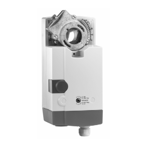
CN20, CN34 SERIES
NON-SPRING RETURN DIRECT-COUPLED DAMPER ACTUATORS
FOR MODULATING AND FLOATING / 2-POSITION CONTROL
GENERAL
These direct-coupled damper actuators provide modulating
control for:
•
air dampers,
•
VAV units,
•
air handling units,
•
ventilation flaps,
•
louvers, and
•
reliable control for air damper applications with up to
2
4.6 m
/ 50 sq.ft. (20 Nm / 177 lb-in) or 7.8 m
(34 Nm / 300 lb-in) (seal-less dampers; air friction-
dependent).
FEATURES
•
•
Access Cover to facilitate connectivity
•
Service/Off for safe & easy servicing
•
Rotation direction selectable by switch
•
Declutch for manual adjustment
•
Mechanical end limits
•
Field-installable auxiliary switches
•
Mountable in any orientation (no IP54 if upside down)
•
Mechanical position indicator
•
CE and UL certified
® U.S. Registered Trademark
Copyright © 2008 Honeywell Inc. • All rights reserved
SPECIFICATIONS
Supply voltage
Nominal voltage
All values stated hereinafter apply to operation under
nominal voltage conditions.
Power consumption
CN7220A2007
CN7234A2008
Ambient limits
Ambient operating limits
Ambient storage limits
Relative humidity
Safety
Protection standard
Protection class
Overvoltage category
Lifetime
Full strokes
Repositions
Mounting
Round damper shaft
Square damper shaft
Shaft length
Control signal
Input impedance
2
/ 85 sq. ft.
Feedback signal
Limits
End switches (when included)
Rating
Triggering points
Torque rating
CN7220A2007
CN7234A2008
Runtime
Rotation stroke
Weight (without cables)
Noise rating
Certification
PRODUCT DATA
24 Vac/dc ±15%, 50/60 Hz;
24 Vac/dc, 50/60 Hz;
6 VA / 3 W
6 VA / 3 W
-20...+60 °C (-5...+140 °F)
-40...+80 °C (-40...+175 °F)
5...95%, non-condensing
IP54 as per EN 60529
II as per EN 60730-1
II
60000
1.5 million
10...27 mm (3/8...1-1/16")
10...18 mm (3/8...11/16");
45° steps
min. 22 mm (7/8")
0(2)...10 Vdc
0(4)...20 mA
>100 kΩ [0...10 V]
500 Ω [0...20 mA]
± 1 mA at 0...10 V
5 A (resistive) / 3 A (inductive)
5° / 85°
20 Nm (177 lb-in)
34 Nm (300 lb-in)
95 sec (60 Hz) / 110 sec (50 Hz
or DC supply)
95° ± 3°
see "Dimensions" on page 8
1.35 kg (3 lbs.)
40 dB(A) max. at 1 m
CE & UL
EN0B-0341CH33 R0803A
Advertisement
Table of Contents

Related Manuals for Honeywell CN34 Series


Summary of Contents for Honeywell CN34 Series
- Page 1 Mountable in any orientation (no IP54 if upside down) 40 dB(A) max. at 1 m Noise rating • Mechanical position indicator CE & UL Certification • CE and UL certified ® U.S. Registered Trademark EN0B-0341CH33 R0803A Copyright © 2008 Honeywell Inc. • All rights reserved...
- Page 2 CN20, CN34 SERIES DAMPER ACTUATOR FOR MODULATING AND FLOATING CONTROL MODELS Model # Description 20Nm,24Vac/Vdc, Modulating and floating/2-position control, Non-Spring return, Voltage Feedback CN7220A2007 Signal and without aux. Switch 34Nm,24Vac/Vdc, Modulating and floating/2-position control, Non-Spring return, Voltage Feedback CN7234A2008 Signal and without aux. Switch PRODUCT IDENTIFICATION SYSTEM C –...
- Page 3 CN20, CN34 SERIES DAMPER ACTUATOR FOR MODULATING AND FLOATING CONTROL Modulating Run Mode • 10-2V, modulating control; floating/2-position control, ccw If the function selection switch has been set to one of the four positions (2-10V, 0-10V/Dir, 10-0V/Rev, 10-2V) – and the actuator is wired as modulating mode (see A1) –...
- Page 4 CN20, CN34 SERIES DAMPER ACTUATOR FOR MODULATING AND FLOATING CONTROL Adaption will be carried out only when: • Modulating models only, such as CN7220A2007, upper dead band (9.76 to 10.0 V) CN7234A2008, etc, • actuator is wired in modulating mode (see Fig. A1) •...
- Page 5 CN20, CN34 SERIES DAMPER ACTUATOR FOR MODULATING AND FLOATING CONTROL Voltage/Current Control Signal Selection Dip Switch actuator scale: clockwise In its default shipping position, the voltage/current control - 2 .5 92.5 signal dip switch (see Fig. 7) is set to OFF (= voltage control).
- Page 6 CN20, CN34 SERIES DAMPER ACTUATOR FOR MODULATING AND FLOATING CONTROL Stroke Limitation with Mechanical End Limits (models with internal switches) OPTIONAL ACCESSORIES The mechanical end limits enable the stroke to be limited from 0...90° in increments of 5°. The following optional accessories can be ordered separately.
- Page 7 CN20, CN34 SERIES DAMPER ACTUATOR FOR MODULATING AND FLOATING CONTROL Wiring Diagrams CN7220A2007, CN7234A2008 MODULATING CN7220A2007, CN7234A2008 FLOATING CN7220A2007, CN7234A2008 2-POS END SWITCHS (Models with switch only) NOTE: Internal end switches S1 and S4 must be connected to the same power source.
- Page 8 CN20, CN34 SERIES DAMPER ACTUATOR FOR MODULATING AND FLOATING CONTROL DIMENSIONS Manufactured for and on behalf of the Environmental and Combustion Controls Division of Honeywell Technologies Sàrl, Ecublens, Route du Bois 37, Switzerland by its Authorized Representative: Automation and Control Solutions Honeywell International Inc.
Need help?
Do you have a question about the CN34 Series and is the answer not in the manual?
Questions and answers