
Related Manuals for Roland SOLJET PRO III XJ-640


Summary of Contents for Roland SOLJET PRO III XJ-640
-
Page 1: Setup Guide
Setup Guide Read this first. This describes the setup tasks and important conditions about the installation location that must be met in order to enable use of this machine. - Page 2 Roland DG Corp. assumes no responsibility for any direct or indirect loss or damage which may occur through use of this product, regardless of any failure to perform on the part of this product. Roland DG Corp. assumes no responsibility for any direct or indirect loss or damage which may occur with respect to any article made using this product.
-
Page 3: Table Of Contents
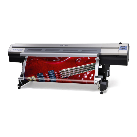
This document is the setup guide for the XJ-740, the XJ-640, and the XJ-540. Also, most of the figures in this document depict the XJ-740. Company names and product names are trademarks or registered trademarks of their respective holders. http://www.rolanddg.com/ Copyright © 2007-2011 Roland DG Corporation... -
Page 4: To Ensure Safe Use
To Ensure Safe Use Improper handling or operation of this machine may result in injury or damage to property. Points which must be observed to prevent such injury or damage are described as follows. About WARNING and CAUTION Notices Used for instructions intended to alert the user to the risk of death or severe injury should the WARNING unit be used improperly. - Page 5 To Ensure Safe Use Incorrect operation may cause injury WARNING CAUTION Exercise caution to avoid being pinched or Be sure to follow the operation procedures becoming caught. described in this documentation. Never Inadvertent contact with certain areas may allow anyone unfamiliar with the usage or cause the hand or fingers to be pinched or handling of the machine to touch it.
- Page 6 Continuing to use the machine may result in disconnect the power cord and contact your fire, electrical shock, or injury. Contact your authorized Roland DG Corp. dealer. authorized Roland DG Corp. dealer. Never place any flammable object nearby. Never use a combustible aerosol spray nearby.
- Page 7 To Ensure Safe Use Important notes about the power cord, plug, and electrical outlet Never place any object on top or subject to damage. Never allow to get wet. Never bend or twist with undue force. Never make hot. Never pull with undue force. Dust may cause fire.
- Page 8 To Ensure Safe Use Ink, cleaning fluid, and discharged fluid are flammable and toxic WARNING CAUTION Ensure adequate ventilation for the work Keep open flame away from the work area. area. Failing to perform ventilation may result in a Ink and discharged fluid are flammable. health hazard or danger of combustion due Never store ink, cleaning fluid, or dis- to ink fumes.
- Page 9 To Ensure Safe Use This machine weighs 250 to 300 kg (550 to 660 lb.). Media weighs 30 to 50 kg (66 to 110 lb.). WARNING WARNING Install the machine in a location that is Be sure to lock the stand's casters. level, stable, and able to bear the weight If the machine should begin to topple, a major of the machine.
-
Page 10: Warning Labels
To Ensure Safe Use Warning Labels Warning labels are affixed to make areas of danger immediately clear. The meanings of these labels are as follows. Be sure to heed their warnings. Also, never remove the labels or allow them to become obscured. Caution: Moving Print Heads The print heads inside the cover move at high speed and pose a hazard. -
Page 11: Pour Utiliser En Toute Sécurité
Pour utiliser en toute sécurité La manipulation ou l'utilisation inadéquates de cet appareil peuvent causer des blessures ou des dom- mages matériels. Les précautions à prendre pour prévenir les blessures ou les dommages sont décrites ci-dessous. Avis sur les avertissements Utilisé... - Page 12 Pour utiliser en toute sécurité L'utilisation incorrecte peut causer des blessures ATTENTION ATTENTION S'assurer de suivre les procédures Ne jamais tenter de démonter, de réparer d'utilisation décrites dans la documenta- ou de modifier l'appareil. tion. Ne jamais permettre à quiconque ne Le non-respect de cette consigne risque de connaît pas le fonctionnement ou la ma- provoquer un incendie, un choc électrique ou...
- Page 13 Continuer à utiliser l'appareil peut causer un électrique. Si un objet ou du liquide s'infiltre incendie, un choc électrique ou des blessures. dans l'appareil, débrancher immédiatement le Communiquer avec le représentant Roland câble d'alimentation et communiquer avec le DG Corp. Autorisé. représentant Roland DG Corp. autorisé.
- Page 14 Pour utiliser en toute sécurité Remarques importantes à propos du câble d'alimentation, de la fiche et de la prise électrique Ne jamais laisser l'eau toucher le câble, la fiche ou Ne jamais déposer aucun objet sur le câble, sur la la prise.
- Page 15 Pour utiliser en toute sécurité L'encre, les liquides nettoyants et les liquides usées sont inflammables et toxiques ATTENTION PRUDENCE Ne pas approcher une flamme nue de S'assurer que le lieu de travail est bien l'espace de travail. aéré. L'encre et les liquides usés sont inflam- L'absence d'aération adéquate peut créer mables.
- Page 16 Pour utiliser en toute sécurité Cet appareil pèse de 250 à 300 kg (550 à 660 lb.) Le support pèse de 30 à 50 kg (66 à 110 lb.) ATTENTION ATTENTION S'assurer de verrouiller les roulettes de Installer l'appareil à un endroit stable et plat la base.
- Page 17 Pour utiliser en toute sécurité Vignettes d'avertissement Des vignettes d'avertissement sont apposées pour qu'il soit facile de repérer les zones dangereuses. La signification des vignettes est donnée ci-dessous. Respecter les avertissements. Ne jamais retirer les vignettes et ne pas les laisser s'encrasser. Attention : Têtes d'impression mobiles Les têtes d'impression sous le couvercle se déplacent à...
-
Page 19: Setup Guide
Setup Guide... -
Page 20: Installation Environment
1. Installation Environment Deciding On an Installation Site Install in a quiet, stable location offering good operating conditions. An unsuitable location can cause accident, fire, faulty operation, or breakdown. WARNING Install the machine in a location that is level, stable, and able to bear the weight of the machine. -
Page 21: Temperature And Humidity
1. Installation Environment Temperature and Humidity Maintain the specified temperature and humidity even when the machine is not in use. Temperatures that are too high may degrade the ink and cause malfunction. Temperatures that are too low may cause the ink to freeze and damage the heads. During operation : Temperature 20 to 32˚C (68 to 90˚F), relative humidity 35 to 80% (no condensation) During non-operation : Temperature 5 to 40˚C (41 to 104˚F), relative humidity 20 to 80% (no condensation) Installation Space... -
Page 22: Included Items
2. Included Items The following items are included with the machine. Make sure they are all present and accounted for. Stay Dancer roller Stand leg (Left) Stand leg (Right) Rail slider Paper tube Media holders and retain- Shafts ing screws Shaft clamps Arm and arm retaining screw Ink-cartridge tray... -
Page 23: Assembling And Installing
3. Assembling and Installing Step 1: Assemble the Stand WARNING Unpacking and installation must be carried out by eight or more persons (by six or more persons for the XJ-540). Otherwise the machine or the stand may fall, resulting in injury. Attach the stand legs to the stay. - Page 24 3. Assembling and Installing Tighten the remaining bolts. Fully tighten all bolts to secure the stay and stand legs completely. Lock all casters and remove the accessories box. Hexagonal Hexagonal wrench wrench Bolts Bolts 4 places 4 places Lock Caster...
- Page 25 3. Assembling and Installing Attach the rail slider and the arm. Attach the arm to the rail slider, securing it secure with the arm retaining screw. Rail slider Orient this side toward the rear. Arm retaining screw Mount the rail slider on the stand legs and secure it in place with the bolts. Line up the tab with the slot in the rail slider and, working with the right stand leg first, secure in place.
- Page 26 3. Assembling and Installing Attach the dancer roller and mount the paper tube. Attach the dancer roller and secure it in place with the bolts. Working from the right side first, secure in place. Dancer roller Line up with the bolt hole and secure in place. Line up with the bolt hole and secure in place.
- Page 27 3. Assembling and Installing Mount the paper tube and secure the arm in place. First, fit the paper tube securely onto the end cap on the same side as the right stand leg. Next, press the end cap on the same side as the arm into the paper tube and securely fit the end cap into the paper tube. Finally, secure the arm in place using the arm retaining screw.
-
Page 28: Step 2: Mount The Machine
3. Assembling and Installing Step 2: Mount the Machine WARNING This task must be carried out by eight or more persons (by six or more persons for the XJ-540). Otherwise the machine or the stand may fall, resulting in injury. Procedure Place the machine on the stand. -
Page 29: Step 3: Install The Drain Bottle
3. Assembling and Installing Step 3: Install the Drain Bottle Procedure Remove the drain-tube cover. Drain-tube cover Secure the bottle stand in place. Using the bolts that held the drain-tube cover in place, secure the bottle stand in place. Bottle stand Remove the lid from the drain bottle. - Page 30 3. Assembling and Installing At the location shown in the figure, secure in place the part you removed in step Fasten using the screw provided, which is attached to the underside of the machine. Screw Back of the machine Underside of the machine...
-
Page 31: Step 4: Install The Media Holders
3. Assembling and Installing Step 4: Install the Media Holders Procedure Place the shafts on the stand. Pass the left media holder onto the shafts. Pass it through from the right edge (as seen from the back of the machine). Engage onto the shaft at the front of the... - Page 32 3. Assembling and Installing In the same way, pass the right media holder onto the shafts and attach the retaining screw. Retaining screw Tighten loosely. Attach the shaft clamps to secure the shafts in place. Hexagonal wrench Hexagonal wrench Bolt Bolt Shaft clamp...
-
Page 33: Step 5: Attach The Ink-Cartridge Tray
3. Assembling and Installing Step 5: Attach the Ink-cartridge Tray Procedure Loosen the upper screws. Remove the lower screws. Mount the ink-cartridge tray on the upper screws. Hang on the upper screws. Ink-cartridge tray Secure the ink-cartridge tray in place with the four screws (two upper and two lower). -
Page 34: Step 6: Remove The Packing Materials
3. Assembling and Installing Step 6: Remove the Packing Materials Packing materials are attached to the machine to protect it from vibration during transportation. When installation is com- plete, remove them. Remove all packing materials. Any that remain may cause faulty operation or breakdown when the ... -
Page 35: Connect The Cables
4. Connect the Cables Connect the Take-up Unit Cable Peel off the tape. Pass the take-up unit cable through Cable clamps at the locations shown in the figure, and connect it. Take-up unit cable Take-up unit... -
Page 36: Connect The Power Cord And The Network Cable
4. Connect the Cables Connect the Power Cord and the Network Cable WARNING Connect to an electrical outlet that complies with this machine's ratings (for volt- age, frequency, and current). Incorrect voltage or insufficient current may cause fire or electrical shock. WARNING Connect to ground. -
Page 37: Installing The Ink Cartridges
5. Installing the Ink Cartridges Filling with Ink for the First Time Special procedures are required when installing ink cartridges for the first time. These are required only once, when installing ink cartridges for the first time after shipment from the factory. Firstly, clean the print heads with the cleaning cartridges, and then fill with the inks of each color. - Page 38 5. Installing the Ink Cartridges Switch on the main power switch. Main power switch Hold down and press the sub power switch. to select the language you want. MENU LANGUAGE ENGLISH Press to select the unit of measurement you want LENGTH UNIT (for length).
- Page 39 5. Installing the Ink Cartridges Pull out the cleaning cartridges. REMOVE SOL CL Insert the cleaning cartridges YOU PULLED OUT into slots 1, 6, 7 and 12. SET SOL-CL LIQUID FILLING INK... >>>> Pull out the cleaning cartridges. REMOVE SOL CL ...
- Page 40 5. Installing the Ink Cartridges Insert the ink cartridges for the respective colors. Before you insert the ink cartridge for each color, gently shake the cartridge. Insert the ink cartridge for each color. SET SOL CRT. 1 2 3 4 5 6 7 8 9 10 11 12 Insert into the slot of the matching color.
-
Page 41: Network Settings
6. Network Settings Introduction This machine has a built-in print server as a network interface. When you use the print server, you can send printing data to the machine from anywhere on the network. TCP/IP is used as the protocol. Make sure the machine is connected to the network by an Ethernet cable. - Page 42 6. Network Settings Click [Properties]. If you're using Windows Vista and the [User Account Control] dialog box appears, click [Allow]. The [Local Area Connection Properties] dialog box appears. Select [Internet Protocol Version 4 (TCP/IPv4)] (Windows Vista) or [Internet Protocol (TCP/IP) (Windows XP/2000), then click [Properties].
-
Page 43: Step 2: Make The Network Settings On The Printer
6. Network Settings Step 2: Make the Network Settings on the Printer Important The addresses used in this section are merely example settings. For detailed information about the set- tings, consult your network administrator. Set the IP address. Press MENU Press several times. -
Page 44: Step 3: Make The Port Settings For The Software Rip
6. Network Settings Repeat to set the subnet mask. SUBNET MASK When you've finished making the setting, press 255 . 255 . 255 . 000 Press W 1346 mm Press to go back to the original screen. SETUP SHEET ROLL If you're using one computer and one machine, this completes the settings to make on the printer. - Page 48 R3-110119...