Table of Contents
Advertisement
Advertisement
Table of Contents

Subscribe to Our Youtube Channel
Related Manuals for Crow Shepherd


Summary of Contents for Crow Shepherd
- Page 1 INSTALLATION MANUAL...
- Page 2 thecrowgroup.com Page | 1...
-
Page 3: Table Of Contents
Table of Contents The Shepherd™ Architecture ............................4 Features ................................4 Overview & Communication Capabilities ........................6 Installing the Shepherd™ ............................10 Configuring the Shepherd™ ............................11 Web Installer Access ............................. 11 Quick Install Guide ..............................12 User Types & Pendants ............................15 User Settings ............................... - Page 4 Chime Reset Mode ............................... 31 Signals to Output ..............................32 Timing ................................33 Alarm to Output ..............................33 Report Channels ..............................35 Channel Type............................... 35 Settings................................36 Area account numbers ............................36 Reporting Options ..............................37 Radio Keypads ..............................39 SH-KP Icon Keypad Overview ..........................
-
Page 5: The Shepherd™ Architecture
The Shepherd™ Architecture Features Up To 16 Users Codes and/or pendants Up to 32 ISM (RF) zones Up to 32 DECT zones Up to 64 2 Way Wireless Zones Working modes options (normal, 24H, Chime…..) Remotely zone configuration Zone supervision... - Page 6 Freewave2™ Two Way ISM GFSK with 5 frequencies & LBT Communication Protocol DECT ULE Frequency Bands (MHz) 868MHz or 916MHz Operating Range Up to 600 meters open space 32 wireless zones Zones Number 32 DECT devices Available Partitions 1 Installer code Installer and User Codes 32 Users Arming Modes...
-
Page 7: Overview & Communication Capabilities
Overview & Communication Capabilities Front View Led Indications Status LED Power LED Communication LED System is armed System is in Arm process RED Blink Burglary Alarm RED Blink RED Blink Panic Alarm RED Blink RED Blink System is disarmed and Ready to Arm Green System is disarmed and NOT Ready to Arm Green / RED Blink... - Page 8 Rear View: thecrowgroup.com Page | 7...
- Page 9 Peripherals Architecture thecrowgroup.com Page | 8...
- Page 10 Communication Architecture thecrowgroup.com Page | 9...
-
Page 11: Installing The Shepherd
Installing the Shepherd™ Note: Be sure that the control panel is mounted near a socket outlet that is easily accessible. The socket outlet for the power supply of the control panel should have its own fuse circuit Use Philips screwdriver to unscrew the 2 holding screws located at the bottom of the panel The screws are handling by a hidden spring. -
Page 12: Configuring The Shepherd
The configuration of the Shepherd™ panel has to be performed through the web installer interface. This part of the CrowCloud™ allows access to an online full configuration interface of the Shepherd™ control panel. The below chapter explains all available options (Version 1.0.0). -
Page 13: Quick Install Guide
Shepherd™ panel offers up to 4 areas (partitions), select the Area to change its name (Ex: Home) Zones _______________________________________________________________________________________________________________________ Shepherd panels offers up to 64 wireless zones (32 ISM and 32 DECT ULE), click on required zone to display its options. Insert unique ID number of the device and give it a name. - Page 14 TCP/IP: By default, the DHCP is active; the router will assign the internal IP of the Shepherd™. You can assign a dedicated IP address to the panel by filling its static IP, Subnet mask and its Gateway (address of the router).
- Page 15 After configuration of your panel, go to http://Crowcloud.com and proceed with the user registration to your Shepherd™ panel. The Crow Cloud personal user webpage give to the end user direct access to all of its registered control panels and: Monitor and Control panel and connected devices ...
-
Page 16: User Types & Pendants
Preliminary Important Note: Configuration changes will take effect only when you will send the updated configuration to the control panel. We highly recommend saving your latest configuration before each update. User Types & Pendants Click on the user to display its available options. User Settings Parameter Description... -
Page 17: User Type
User Type Parameter Description Default Configuration Radio keys can be used to Arm/Disarm all or part of the alarm or they can operate outputs directly', Unlike user codes, a radio key cannot be assigned to a keypad so if a Pendant User Disable radio key is assigned to more than one output and the... -
Page 18: Permissions
Permissions Parameter Description Default Configuration User can view memory and If this option is off user cannot enter to view memory log, Enable for all users status statuses and active time zones. User can change his code and If a User has this option on, they can access User Program Enable for all users name Mode and change their code number and name... -
Page 19: Areas Settings
Areas Settings Click on an Area to display its available options. Area Names Parameter Description Default Configuration Area # Area Name Enter name to identify the Area Settings Parameter Description Default Configuration If this option is turned on, the BYPASS button cannot access Code required to bypass zones Bypass Mode directly. -
Page 20: Timers And Delays
Timers and Delays Parameter Description Default Configuration Each Area can have its own exit delay time. The delay can be programmed from 1-255 seconds in one Exit Delay Time (sec) 60 seconds second increments. If the exit delay is set to '0' the panel will be instantly armed. -
Page 21: Signals To Output
Signals to Output Parameter Description Default Configuration For monitoring purposes, an Arm indication can be assigned to an Output. Arm Area Indication No Outputs selected It could be used to start a video recorder or similar device. to Outputs Each Area can have a separate arm indication assigned to a different output if required For monitoring purposes, a Stay Arm indication can be Stay Arm Area Indication... -
Page 22: Radio Zones
Radio Zones The Shepherd™ Panel supports up to 64 wireless zones: 32 Two-Way ISM zones (from 1 to 32) and 32 DECT ULE Zones (from 33 to 64). We invite you to visit our website http://www.thecrowgroup.com for more information on our Two-Way wireless ISM and DECT ULE detectors range. - Page 23 Wireless Glass Break Detector Available Options LED Enable: Activation or not of the LED indicators Supervision: Period between each supervision in minute (from 7 to 30) Glass-break sens: Sensitivity of the micro elect (Low, Mid or High) GBD AGC: TBD (0%, 25%, 50% or 75%) MEMS Fall Sensor: MEMS Vibrat sens: All sens for sign:...
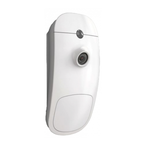
- Page 24 Wireless PIR Camera Available Options LED(s) state: Activation or not of the LED indicators Camera state: Activation of the Camera module Number of pulses: Pulse count for each motion detection (1,2 or3) Pet Immunity: Activation of the 15Kg Pet immunity Gain control: Sensitivity of the PYRO sensor Picts per set: Number of pictures sent in case of alarm JPEG mode: Regular or Differential (Video Motion Detection)
-
Page 25: Zone Status
Zone Status Parameter Description Default Configuration Non Active until you Zone is active Zone will be monitored by the panel. learn a new zone Zone will cause alarm if triggered when Stay Mode is armed. This Stay mode zone feature is normally used for arming just part of the alarm at night All zones selected time. -
Page 26: Working Mode
Working Mode Parameter Description Default Configuration Normal Zone without any special behavior. All zones selected If this option is ON the zone will be constantly monitored regardless of the arm/disarm state of the panel. If the 24 Hour zone also has 24-hour zone No Zones selected an entry delay programmed, this delay will apply. -
Page 27: Zones Options
Zones Options Parameter Description Default Configuration If this option is turned on and the zone is set as a 24 Hour type, Zone will not report 24h when an alarm is generated, the alarm will not be transmitted No Zones selected alarm to the monitoring station via the dialer Zone belongs to bypass group. -
Page 28: Re-Trigger
Re-trigger Parameter Description Default Configuration Each Zone has its own alarm re-trigger count. A value of 0 programmed at this location results in unlimited alarms for that zone during an armed period but a count of 1-15 will shut down the zone once the programmed count has been reached. - Page 29 Alarm to Outputs (cont) Parameter Description Default Configuration Zone tamper can trigger selected output(s) for Zone tamper to outputs No Outputs selected local alarm signaling. If a zone is programmed as a Chime zone and it activates, the zone can trigger selected Outputs for local alarm signaling.
-
Page 30: Radio Outputs
Radio Outputs Click on the output to display its available options. Radio Output Parameter Description Default Configuration Output Name Set Output Name Output # Save new radio Output in memory Serial Number Enter the Unique ID serial of the wireless sounder "0"... -
Page 31: Settings
Settings Parameter Description Default Configuration This option is used to invert the normal state of the output. The panel uses open collector transistor switches and the Disable Invert Output default state of all outputs is OFF (open). When in alarm the transistor is turned ON and the output goes low (0V). -
Page 32: Type Of Output
Type of Output Parameter Description Default Configuration All Outputs are selected Constant The output will change its state when an alarm occurs as constant output This option produces a single pulse at the output when an Single Pulse Not selected alarm occurs (the pulse time is programmed value). -
Page 33: Signals To Output
Signals to Output Parameter Description Default Configuration Not selected Mains Fail to Output This option is used to assign a Mains Fail alarm to an Output This option is used to assign a Fuse Failure alarm to an Output. The on-board fuses are thermally activated. If Not selected Fuse Fail to Output excessive current is drawn from a fuse it will disconnect the... -
Page 34: Timing
Timing Parameter Description Default Configuration The 'On' delay allows the operation of the Output to be Output ON Delay Time delayed by the time programmed at this location. If set to '0' Value of "0" (seconds) there will be no on delay and the Output will operate the instant it is turned on. - Page 35 Alarm to Outputs (cont) Parameter Description Default Configuration Zone tamper can trigger selected output(s) for Tamper from zones No Outputs selected local alarm signaling. If a zone is programmed as a Chime zone and it activates, the zone can trigger selected Outputs for local alarm signaling.
-
Page 36: Report Channels
Report Channels Click on a report channel to display its options. Channel Type Parameter Description Default Configuration Channels #2, #6 and #8 are selected Set channel type as TCP/IP TCP_IP Note: Need to set Ethernet enabled to use this type of channel The channel #8 is dedicated to the CrowCloud™™... -
Page 37: Settings
This option is available only if the specified channel is defined as TCP/IP, GPRS or Wi-Fi Port Defines report protocol pot (up to 4 digits) 4700 predefined (Crow) This channel will be activated if the main channel has failed to Channel Backup No channels selected open connection or deliver a message. -
Page 38: Reporting Options
Reporting Options Parameter Description Default Configuration Video Event Report This channel transmit Video verification (TBD) All channels selected If this option is selected the panel will report a Mains failure Report Mains Failure after the report delay time has expired All channels selected (see "Clock and Timers"... - Page 39 Parameter Description Default Configuration If this option is on the panel will report all zone restores. If this All channels selected Report Zone Restores option is turned off the panel will only report the alarms If the panel has been configured for Delinquency monitoring and All channels selected Report Delinquent an area has not been armed for the time set at, a Delinquency...
-
Page 40: Radio Keypads
Radio Keypads SH-KP Icon Keypad Overview The SH-KP is an optional two-way wireless keypad with built-in proximity RFID tag reader compliant with RFID tags including variation of millions ID combinations and numerical keypad. For RFID control, please use access tag. Press the key "Enter" and serve the tag. For learning procedure, please refer to the para "Radio Keypad"... -
Page 41: Area Assignment
Parameter Description Default Configuration Beeps enabled on Enable Beeps Enable beeps on selected keypad keypads 1 and 2 This option allows the information on a keypad to be turned No armed indications OFF when the panel is in the Armed or Stay Armed state. The No Keypad selected screen returns to the normal state on disarming of the system. -
Page 42: Communication Options
Communication Options Remote Access Parameter Description Default Configuration Remote Access It is defined up to 8 characters password for remote connection 12345678 Password (CrowCloud™ and Mobile applications) mediator.CrowCloud™.xyz Remote Access This parameter defines IP-address or DNS name of the remote Server Address access server. -
Page 43: Gsm
Parameter Description Default Configuration If this option is on, the GPRS Data is Enabled. GSM IP Enabled This communication method suits for Data connection to Enabled Monitoring Station or Server. If this option is on, the GSM CID is Enabled. GSM SMS Enabled This communication method suits for connection to Monitoring Enabled... -
Page 44: Dect
Click this button to delete DECT Panic Button Empty DECT PIN Code PIN code of the DECT voice unit (if needed) Empty Crow Electronic Engineering Ltd. Is an active contributor to the ULE Alliance with a full range of DECT ULE products thecrowgroup.com Page | 43... -
Page 45: Rf Repeater
RF Repeater Parameter Description Default Configuration The Repeater supports up to 5 frequencies to prevent jamming. Starting RF Channel You can choose frequency range from 1 to 5. Enter the unique ID of the device Learn Repeater Press Done and Save the configuration Delete Repeater Click this button to delete the selected wireless repeater Time Zones... -
Page 46: Area Assignment
Area Assignment Parameter Description Default Configuration If area assigned to time-zone it will automatically arm when time- zone starts and disarmed when it finishes. You can assign more than Time Zone Assigned to one time-zone to each area. If assigning multiple time-zones you No Zones selected Area should insure that they do not overlap as this could cause... -
Page 47: Miscellaneous
Miscellaneous Clock and Timers Parameter Description Default Configuration If you are in Daylight Saving Time when the alarm system is installed you MUST turn this option ON so that the panel knows that Daylight Saving Time is currently active. Daylight Saving Not Enabled Failure to do this will not allow the clock to automatically adjust to the correct time when Daylight Saving Time Ends... -
Page 48: Panel Options
Panel Options Parameter Description Default Configuration This code is used to enter into full Installer Program mode. Installer Code 000000 This code can only be changed while in Installer Program Mode. The Installer Code must be between 4-8 digits in length The duress digit can be a number from 1-9 (a value of '0' means the duress function is disabled). - Page 49 If this option is selected and a Detector Supervision alarm has Config mode resets occurred, the alarm cannot be re-armed until the Installer has Not selected supervision alarms reset the alarm. if this option is selected, the panel cannot be armed if the panel battery is low or the AC has failed.
-
Page 50: User Options
User Options Parameter Description Default Configuration If this option is selected, access to view Memory Log, Status Window and Active Time Zones will only be allowed by using an authorized code. Code Required to View If this option is not selected, anyone can access the memory in Not selected Memory disarm mode. -
Page 51: Crowcloud™ Web Services
CrowCloud™ Web Services Your Shepherd™ panel is configured by default for direct communication to CrowCloud™. After configuration of your panel, go to http://Crowcloud.com and proceed with the user registration to your Shepherd™ panel. The Crow Cloud personal user webpage give to the end user direct access to all of its registered control panels. - Page 52 Edit list of registered control panels Click on the desired control panel to access to its monitoring and control Add new control panel to user Areas This part gives control to Shepherd™ panel Areas: Selection of the area to monitor/control ARM:...
- Page 53 Outputs This part gives control Outputs NAME: Name of the outputs (ex: outdoor siren) TYPE: Type of Output: Wired, Siren, Smart Plug… STATE: Info on output trouble STATUS: Activation / Deactivation of the output Users List of active users into the control panel. User position registered in control panel NAME: Name of the user saved in control panel...
- Page 54 Display of the current connection method Ethernet: IP: internal IP of the panel in your network MAC: Ethernet MAC of the Shepherd™ Mask: Network subnet mask Panel: IP of the router ID: Name of the communication method Radio:...
-
Page 55: Mobile Applications
Mobile Applications Friendly user guide will help you register and set up the Panel. Install the Crow Pro application on your smartphone (iOS / Android) or open your web browser http://CrowCloud.com thecrowgroup.com Page | 54... - Page 56 Further, CROW Electronic Engineering Ltd. reserves the right to revise this publication and to make changes to its content, at any time, without obligation to notify any person or entity of such revision changes. These materials are copyrighted and any unauthorized use of these materials may violate copyright, trademark, and other laws.
-
Page 57: Appendix 1: Installer Event Log Messages
Appendix 1: Installer Event log messages AC Fail Loss of AC power from the main panel AC Restored AC power restore on main panel %O activated by %U Output number %d activated by user number %U %O activated by remote control Output number %d activated remote control *%Z Alarm in %A Zone number %Z Alarm in Area number %A... - Page 58 Exiting installer programing from installer web interface or Exit Installer Mode installer app. *Fire Alarm from keypad %d Fire Alarm from keypad number %d *Fire Alarm Reset Fire Alarm Restore Full CFG View by %S1 Full configuration view by Cloud user %S1 *%Z 24 Hour Alarm Zone number %Z 24 hour Alarm *%Z 24 Hour Fire Alarm...
- Page 59 System restarted The control panel has reset Take Picture in %Z Started by %S1 Take picture from PIRCAM Zone %Z started by Cloud user %S1 Take Picture in %Z Success Take picture from PIRCAM Zone %Z Succeed %Z Tamper Tamper alarm from zone number %Z %Z Verified Alarm in %A Verified Alarm from Zone %Z in Area %A Upgrade Failed by %S1...
Need help?
Do you have a question about the Shepherd and is the answer not in the manual?
Questions and answers