Crow Power Wave CR16M User's Operating
Lcd keypad
Hide thumbs
Also See for Power Wave CR16M:
- Operating and programming manual (24 pages) ,
- Operating and programming manual (24 pages)

Related Manuals for Crow Power Wave CR16M


Summary of Contents for Crow Power Wave CR16M
- Page 1 ELECTRONIC ENGINEERING LTD. Power Wave CR16M- LCD Keypad Users’ Operating and Programming Guide Version P/N 7102265 Rev. C May 2003...
-
Page 2: Table Of Contents
Contents Introduction Meet the Crow Alarm Control System Typical Alarm System Configuration Keypad Description General Description Function Keys Alphanumeric Keys Audible Signals Indicators Display Summary of Functions Operation How to Arm the System before Exit How to Arm the System when Staying Home... - Page 3 How to Change or Add Codes Customizing your Keypad How to Add or Change Telephone Numbers How to set Time and Date How to operate the access control output How to start Walk test Mode How to Adjust Keypad Backlight Level How to Adjust Buzzer Tone PowerWave –...
-
Page 4: Introduction
Introduction Meet the Crow Alarm Control System Thank you for choosing to protect your premises with a PowerWave of Crow Electronic Engineering Ltd. Power Wave of Crow Electronic Engineering Ltd. is a highly advanced, multifunction alarm control system, designed to flawlessly manage your security system at home or at business, protects you against burglary and supports the operation of electronic devices. -
Page 5: Keypad Description
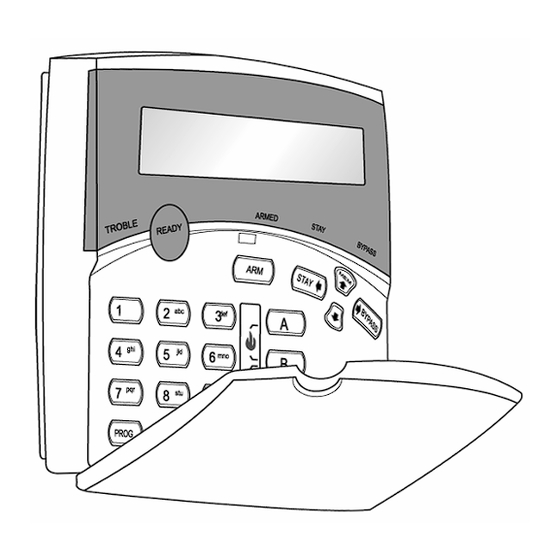
Keypad Description General Description The LCD display shows all the information required to operate the system in a friendly manner and free of flaws. The User communicates with the alarm system via the keypad. The Keypad displays continuous information about the status of the alarm system, and enables the User to operate the system in different modes, change settings and program Users' access codes. -
Page 6: Indicators
Table 1: List of Audible Signals Sound Sequence Description Short beep Once only A key in the keypad has been pressed 3 short beeps Once only Operation carried out successfully Long beep Once only Illegal operation, or wrong key pressed Slow beeping Through the Exit or Exit or entry delay warning when arming... -
Page 7: Summary Of Functions
Summary of Functions The system's main functions are listed in Table 3. Table 3: Summary of Functions Function Keys Description Notes Full Initiates full arm C O D E ENTER or Partition Full Arm Initiates full arm Only if enabled by installer Disarm Disarms the system... - Page 8 Function Keys Description Notes Initiate Fire Activates Press Alarm emergency alert simultaneously for 2 seconds Memory Initiates display of Displays events, events from and automatically memory. scrolls to the next event every 2.5 sec. <ENTER> cancels (Use arrow key to memory readout scroll up manually) Chime...
-
Page 9: Operation
Function Keys Description Notes Decrease Hold <CONTROL> CONTROL and press <? > backlight repeatedly to level decrease light Increase Hold <CONTROL> CONTROL buzzer and press <A> tone repeatedly to increase buzzer tone Decrease Hold <CONTROL> CONTROL buzzer and press <B > tone repeatedly to lower buzzer tone... -
Page 10: How To Arm The System When Staying Home
Areas Exiting There is a exit delay prior to the system being armed. During this delay time you can leave the premises. At the end of the procedure. the ARMED indicator lights up to indicate that the system is armed, and the system message is displayed. (The indicators may go out after a few seconds, depending on the installer's setting). -
Page 11: How To Arm Partitions
At the end of the procedure, the Stay indicator lights up to indicate that the system is armed and the system message is displayed. (The indicators may go out after a few seconds, depending on the installer's setting). Areas In Stay •... -
Page 12: How To Use Chime ( If Enable By Installer)
Enter the zone number (e.g. 01, 05, 12 in PW16 or 1, 2, 6 in PW4/8) one or more zones. Bypass Zones 01 03 06 Following press <ENTER>, the system displays the bypassed zones. Zone 3 Bypass Zone 3 While in the Bypass mode it is possible to bypass more than one zone, press <BYPASS>, Bypass indicator lights up to indicate that the system is in bypass mode, Add the zone number (e.g. -
Page 13: How To Read System Messages
usual code by one digit. If your code is 345 and 8 is your duress digit, than entering 8345 will modify your code. The modified duress code will disarm the system in a normal w ay, but at the same time will activate the dialer silently to report a “duress event” without arousing suspicion. -
Page 14: How To Display Events From Memory
How to Display Events from Memo ry The system memory stores the last events. Press <MEM > to display list of events. The system will display the last event and automatically scroll to the next one every 2.5 seconds, and a beep is emitted. Use the arrow keys to scroll up manually. Each entry shows the type of event, date and time. - Page 15 The factory default master code (123) is intended as a preliminary control of the alarm system. After PowerWave is installed and put into service, the code can be changed to any code known to the Master user. The Master user can define up to 99 user codes. To limit access rights, the holder of the Master code can ask the installer to define several User profiles.
-
Page 16: Customizing Your Keypad
How to Delete User Code In client mode, press <PROG> and the User number (2 to 100) you intend to delete. The display shows the code. User 8 Code 8765 Press <CONTROL> and<0> simultaneously to delete User code. Press <ENTER> to save the change. -
Page 17: How To Set Time And Date
(In PW16 The six phone numbers are at program address 331 through to 336). (In PW4/8 The six phone numbers are at program address 501 through to 504). (In FW64 – see User's Operating and Programming guide ) While in CLIENT mode, key in the following sequence <PROGRAM> <331> <ENTER> (The address for telephone number 1), The existing number will be flashed out at the Keypad then enter <NEW TELEPHONE #>... -
Page 18: How To Operate The Access Control Output
Where YY = current year, e.g. 02=2002 How to operate the access control output If the alarm system has been set up to allow control of an electric door lock, you can activate the door release function as follows; Press <CONTROL> or Press <CONTROL> enter CODE then <ENTER> The Control LED will lights up while the lock is active and turn off as soon as power is removed from the lock. - Page 19 Table 6: Summery of Alphanumeric Keys Button # Press Press Press Press * (‘) # (<) = (>) A (a) B (b) C (c) D (d) E (E) F (F) G (g) H (h) I (i) J (j) K (k) L (l) M (m) N (n)
-
Page 20: How To Adjust Keypad Backlight Level
To exit Local Edit Program Mode and return to Idle Mode, press <PROG> and then <ENTER>. How to Adjust Keypad Backlight Level The User can adjust the backlight of the keys and LCD display in 16 steps, from Fully illuminated to Off. To increase LCD backlight, hold <CONTROL>... - Page 21 There are no warranties, expressed or implied, of merchantability or fitness for a particular purpose or otherwise, which extend beyond the description on the face hereof. In no case shall Crow be liable to anyone for any consequential or incidental damages for breach of this or any other warranty, expressed or implied, or upon any other basis of liability whatsoever, even if the loss or damage is caused by Crow’s own negligence or fault.
- Page 22 Use the following form to record your changes and customizations. User # Name Device Zone Zone Name Designation...
-
Page 23: Powerwave - Lcd Keypad Assignment
PowerWave – LCD Keypad Assignment Each of the 8 possible LCD keypads that can be connected to your PW control Panel must be set to the suitable type of control panel, and addressed individually to avoid bus conflicts. To assign the KEYPAD Address Switch 1 Switch 2 Switch 3... - Page 24 support@crow.co.il...
Need help?
Do you have a question about the Power Wave CR16M and is the answer not in the manual?
Questions and answers