Table of Contents
Advertisement
Quick Links
Advertisement
Table of Contents

Related Manuals for GVS K-BUS


Summary of Contents for GVS K-BUS
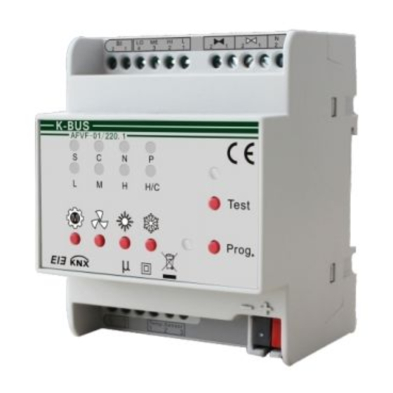
- Page 1 Guangzhou Video-star Electronics Industrial Co., Ltd ○ K-BUS Fan Coil Controller User manual-Ver. 1 AFVF-01/220.1 KNX/EIB Intelligent Installation Systems www.video-star.com.cn marketing@video-star.com.cn Tel.: (8620)39338986 Fax: (8620)39338465...
-
Page 2: Table Of Contents
K-BUS KNX/EIB Fan Coil Controller ○ Contents 1. Overview----------------------------------------------------------------------------------------------------------------------------------- 2 1.1Products and Function Overview-------------------------------------------------------------------------------------------------- 3 2. Technical Data, Dimension and Circuit Diagram----------------------------------------------------------------------------------- 4 2.1 Technical Data------------------------------------------------------------------------------------------------------------------------ 4 2.2 Dimensional Drawing--------------------------------------------------------------------------------------------------------------- 5 2.3Wiring Diagram (Taking Continuous Valve for Example)-------------------------------------------------------------------- 6 3. Project Design and Application--------------------------------------------------------------------------------------------------------7 3.1 General Introduction-----------------------------------------------------------------------------------------------------------------7... -
Page 3: Products And Function Overview
K-BUS KNX/EIB Fan Coil Controller ○ This manual provides detailed technical information about the Fan Coil Controller for users as well as assembly and programming details, and explains how to use the Fan Coil Controller by the application examples. To achieve convenient installation in distribution box, the Fan Coil Controller is designed to a modular installation device, and is installed on 35mm DIN Rail according to EN 60 715. -
Page 4: Technical Data, Dimension And Circuit Diagram
K-BUS KNX/EIB Fan Coil Controller ○ 2. Technical Data, Dimension and Circuit Diagram Fan Coil Controller is a modular installation device, and installed on 35mm DIN Rail in distributor box. It is connected EIB/KNX system via BUS connecting terminal. 2.1 Technical Data... -
Page 5: Dimensional Drawing
K-BUS KNX/EIB Fan Coil Controller ○ Heating/cooling 2button and 1 red & blue LED Programming 1buton and 1 red & green LED Please refer to section 2.3 for location of Button and Indicator LED, and 3.2 for operation description Temperature rang Operation -5℃... -
Page 6: Wiring Diagram (Taking Continuous Valve For Example)
K-BUS KNX/EIB Fan Coil Controller ○ 2.3Wiring Diagram (Taking Continuous Valve for Example) ①Power supply for valve ⑧ Temperature sensor input ② Heating Valve (1-close, 2-open) ⑨ Power supply 230V AC ⑩ manual buttons, from left to right: operation modes, ③... -
Page 7: Project Design And Application
K-BUS KNX/EIB Fan Coil Controller ○ 3. Project Design and Application 3.1 General Introduction Application Program Max. number of Max. number of Max. number of Communication Objects Group Addresses Associations Fan coil Controller The Fan Coil Controller controls Fan’s fan speeds and Valve’s opening degree intelligently by PI Algorithm, and achieve heating/cooling to make rooms comfortable through comparison between setting temperature and actual temperature. -
Page 8: Coil System
K-BUS KNX/EIB Fan Coil Controller ○ fan-speed button; the fan-speed gear is change via a short operation, the current speed is switched on or off via a long operation, and the corresponding indicators would on or off. In this mode, room operation modes cannot be changed, and the control mode only can be returned to the Automatic Control Mode. -
Page 9: Room Temperature Control Mode And Setting Temperature Adjustment
K-BUS KNX/EIB Fan Coil Controller ○ 3.5 Room Temperature Control Mode and Setting Temperature Adjustment Room Temperature Control Mode Room temperature control has 4 modes: comfort mode, standby mode, night mode, and protection mode, and it is used to adjust rooms’ setting temperature, and it can be switched via KNX BUS or room mode button. -
Page 10: Type Of Control
K-BUS KNX/EIB Fan Coil Controller ○ Setpoint adjustment Protection mode: Heating: Setpoint temperature = Threshold value for heat protection Cooling: Setpoint temperature = Threshold value for frost protection Setpoint adjustment is realized via object 5. Note: When user chooses “Heating and cooling ” of “Controller mode in Heating/Cooling” in the parameter window “General”, auto control to toggle heating and cooling is related to setting temperature... -
Page 11: Ets System Parameter Setting Description
K-BUS KNX/EIB Fan Coil Controller ○ PWM control PWM (pulse width modulation) control is based on the actual temperature and set the thermometer calculates a control value, and then calculates the valve opening and closing time of the switch valve is controlled to achieve a comfortable temperature state. -
Page 12: Parameter Window "General
K-BUS KNX/EIB Fan Coil Controller ○ 2. Bus (controlled device) As controlled by the external control fan coil controller role, and its temperature is not monitored and does not output the control value, but by an external controller (e.g., temperature and humidity sensors, temperature control panel, etc.) is sent to the control value for the output control. - Page 13 K-BUS KNX/EIB Fan Coil Controller ○ control the wind speed and valve of external fan coil controller via bus. "Bus" shows that the fan coil controller is controlled by an external controller, i.e. as the controlled device; in this mode, the outputs of the fan coil controller are controlled via bus.
- Page 14 K-BUS KNX/EIB Fan Coil Controller ○ is realized via the communication object 7 and 8. "Local" means that the actual temperature and the set of local parameters to determine the output control of heating or cooling. Parameter:Insensitive zone between heating and cooling Options:...
-
Page 15: Parameter Window: "Temperature Setting
K-BUS KNX/EIB Fan Coil Controller ○ also sent when changes. Parameter:Period of sending fan coil status Options:[min.] 1…255 This parameter sets the period for cyclical sending the RHCC and HVAC status. This parameter is visible when the option "Send cyclically" in the parameter "Send RHCC and HVAC status" is selected. - Page 16 K-BUS KNX/EIB Fan Coil Controller ○ Fig. 4.3.1 parameter window “Temperature setting” Actual temperature Actual temperature, mainly setting the way of collecting temperature, temperature type and correction, monitoring and sending of the temperation and so on. Parameter:Actual temperature from Options:...
- Page 17 K-BUS KNX/EIB Fan Coil Controller ○ This parameter is set to the bus output, or received from the bus type of the actual temperature. "Centigrade" indicates the actual temperature is expressed in degrees Celsius; "Fahrenheit" indicates the actual temperature is Fahrenheit.
- Page 18 K-BUS KNX/EIB Fan Coil Controller ○ temperature returned to normal hair only a "0" (Flase means 0); "Send cyclically" send for the cycle, depending on the setting of the transmission time , time to send a message , but the actual temperature anomalies also sent telegram, and sent at this time to re-cycle timing .
-
Page 19: Parameter Window "Setpoints
K-BUS KNX/EIB Fan Coil Controller ○ Fig. 4.3.2 parameter window “External temperature” 4.4 Parameter window "Setpoints" "Setpoints" parameter setting window is shown in Figure 4.4. It is for setting the basic setpoint temperature of heating or cooling. Divided into "Base setting", "Heating" and "Cooling" three parts, "Heating"... - Page 20 K-BUS KNX/EIB Fan Coil Controller ○ Fig. 4.4.1 parameter window “Setpoints” Base setting Setting the basic setting for either heating or cooling Parameter: Base setpoint temperature Options: [° C] 15 ... 30 This parameter is a reference value to set the set temperature, the set temperature of room modes generated via the value.
- Page 21 K-BUS KNX/EIB Fan Coil Controller ○ Send cyclically This parameter is set to send mode temperature setpoint. "Send on change" means that there is a change occurs when the set temperature set temperature. "Send cyclically" means that periodically sends the temperature setpoint.
-
Page 22: Parameter Window "Controller
K-BUS KNX/EIB Fan Coil Controller ○ value, the controller outputs a control not to fan coil temperature is below the set temperature value; cooling mode when the room is The over-temperature protection mode when the room temperature rises to a set temperature value of the option, the controller outputs a control not to fan coil temperature is higher than the set temperature value. - Page 23 K-BUS KNX/EIB Fan Coil Controller ○ Fig. 4.5 parameter window "Controller" Parameter: Controller setting for heating Parameter: Controller setting for cooling Options: - Slow - Normal - Fast - User defined This parameter is set when setting the heating or cooling of PI corresponding...
-
Page 24: Parameter Window "Fan
K-BUS KNX/EIB Fan Coil Controller ○ Options: - Do not send -Send on change -Send cyclically The transmission control parameters by value. "Do not send" is not sent to the bus control value; "Send on change" for the control value is changed certain value, the controller was sent on to the bus control value;... - Page 25 K-BUS KNX/EIB Fan Coil Controller ○ Fig. 4.6.1 parameter window "Fan" Parameter: Type of fan Options: - No fan - Local (max. 3 speeds) - KNX: on / off -KNX: 3 speeds -KNX: 0 ... 100% This parameter sets the type of the fan.
- Page 26 K-BUS KNX/EIB Fan Coil Controller ○ This parameter is the number of stalls set up wind speed. According to the actual needs of fan coil, the user can select the fan speed is divided into several files. This parameter is only in the parameter "Type of fan" option for the "Local (max.3speeds)", "KNX 3speeds"...
- Page 27 K-BUS KNX/EIB Fan Coil Controller ○ Fig. 4.6.2 fan gear shifting mode Parameter: Minimum delay at starting speed Options: [sec.] 2 ... 255 The parameter sets the minimum delay at the starting speed. Parameter: Changeover delay between fan speeds Options: [sec.] 0.5 ... 10...
-
Page 28: Parameter Window "Heating Valve" And "Cooling Valve
K-BUS KNX/EIB Fan Coil Controller ○ 4.7 Parameter window “heating valve” and “cooling valve’ “Heating valve” and “cooling valve” parameter setting windows are shown in fig. 4.7.1 and fig. 4.7.2. They are respectively used to set some parameters of the heating and refrigeration valves. The following detailed settings for each parameter. - Page 29 K-BUS KNX/EIB Fan Coil Controller ○ Fig. 4.7.2 parameter window “Cooling valve” Parameter : Type of heating valve Parameter: Type of cooling valve Option Parameter:--Raise/lower valve, continuous – Raise/lower valve, pulse width modulation – Thermal valve – BUS valve, continuous –...
- Page 30 K-BUS KNX/EIB Fan Coil Controller ○ Optional: – Normal (de-energised closed) –Inverted (de-energised open) This parameter is to set the direction of the valve switch. Continuous valve "Normal (de-energised closed)" is positive; "Inverted (de-energised open)" to reverse. Switch valves "Normal (de-energised closed)" indicates a normally closed switch; "Inverted (de-energised open)"...
- Page 31 K-BUS KNX/EIB Fan Coil Controller ○ cycle is limited; “BUS valve, continuous” Restricted is made out of a heating or cooling control values. This parameter is only in the parameter entry "Valve adjustment" select “Enable” is visible. To Raise/lower valve, continuous valve as an example, the output value of the diagram Parameter:Duration of 100 % valve stroke time...
- Page 32 K-BUS KNX/EIB Fan Coil Controller ○ Option: -Enable -Disable The parameter settings are automatically corrected for the continuous valve opening. This parameter is only in the parameter entry "Type of heating valve" or "Type of cooling valve" select "Raise / lower valve, continuous" or "Raise / lower valve, pulse width modulation"...
- Page 33 K-BUS KNX/EIB Fan Coil Controller ○ Parameter: Differential value for sending Parameter: Differential value for sending Options: [%] 1 ... 10 This parameter sets the local valve status change. When the valve is continuously changing the local value of the parameter, the controller sends a valve to the bus state values. This parameter is only in the parameter entry "Send heat valve status"...
-
Page 34: Parameter Window "Window Contact
K-BUS KNX/EIB Fan Coil Controller ○ 4.8 Parameter window "Window contact" "Window contact" window is shown in Fig. 4.8. The page is mainly used to set the window parameter switch status parameters. The following detailed description of each parameter settings. - Page 35 K-BUS KNX/EIB Fan Coil Controller ○ When the controller detects the windows open, the controller will output parameter entry "Controller function for open window" in the parameters set. Parameter: Type of local window contact Options: No local sensor open Contact open: window...
-
Page 36: Parameter Window "Temperature Monitoring
K-BUS KNX/EIB Fan Coil Controller ○ Control value = 0 (all off) Control value unchanged The parameter setting window is opened for the operation of the controller . "Normal" fan coil controller output at normal control value; "Control value = 0 (all off)" fan coil controller output control value is 0, then the fan coil valves and wind are closed;... - Page 37 K-BUS KNX/EIB Fan Coil Controller ○ Parameter:Repetition of frost alarm Options: Do not send Send on change Send cyclically Setting the mode of sending out the frost alarm. “Do not send” means don’t send the frost alarm to the bus;...
- Page 38 K-BUS KNX/EIB Fan Coil Controller ○ “Do not send” means don’t send the alarm to the bus; “Send on chang” means sending the signal to the bus when the alarm is changed; “Send cyclically” means sending the signal periodically, and also the time when the alarm is changed, after that, the cycle time is recounted.
-
Page 39: Parameter Window "Scene
K-BUS KNX/EIB Fan Coil Controller ○ “1 Bit” means when whatever one alarm of the error sets is happened, controller will send the signal of alarm in 1 bit. “1 Byte” means each alarm of the error sets, each number represents:... - Page 40 K-BUS KNX/EIB Fan Coil Controller ○ Fig. 4.10 parameter s window “Scene” Parameter:Use scenes Options:Enable Disable Setting the scene. There are 6 scenes can be choosed. Parameter:Scene 1-6 Options:Enable Disable There are 6 scenes can be choosed, but each time, you can select only 1 scene.
-
Page 41: External Control Parameter Setting Interface
K-BUS KNX/EIB Fan Coil Controller ○ Frost protection Parameter:Fan Options: No change High Medium Setting the wind speed of each scene. “No change” means keep the same speed. “High”, “Medium”, “Low” means the different wind speed. “Off” means to shut down the fan. - Page 42 K-BUS KNX/EIB Fan Coil Controller ○ External Control "General" parameter setting interface as shown in Figure 4.11.1, following detailed description of each of the parameter settings. Fig. 4.11.1 External Control "General" parameter setting interface Parameter: Controller from Options: Local This parameter is to set the fan coil controller.
- Page 43 K-BUS KNX/EIB Fan Coil Controller ○ Parameter: Valves Options: 1 channels for heat / cool (2 pipes system) 2 Channels for heat / cool (4 pipes system) This parameter is set up out of the water pipe fan coil type.
- Page 44 K-BUS KNX/EIB Fan Coil Controller ○ The parameter values for the monitoring of external control time period, if the control value has not been updated, but longer than the time set this option; it is considered an external controller error, the controller based on the output of user-set parameters.
-
Page 45: Description Of The Communication Objects
K-BUS KNX/EIB Fan Coil Controller ○ 5. Description of the communication objects Communication objects are devices on the bus to communicate with other media devices , That is only the communication objects can communicate on the bus. The following details description of the function of each communication object. - Page 46 K-BUS KNX/EIB Fan Coil Controller ○ Object 4: The benchmark set temperature. As the setting value for the reference value of the actual output. The value of the existing heating but also cooling the case with dead zone temperature is used to determine the current status of the refrigeration or heating.
- Page 47 K-BUS KNX/EIB Fan Coil Controller ○ when the object 9, the object 10 and object 11 received are zero, then the room is ready mode control mode. 1byte: Enter the number and pattern relationship is as follows: Bit no: 0: Automatic...
- Page 48 K-BUS KNX/EIB Fan Coil Controller ○ Presence sensor Input, presence detector 1bit C,W,U [1.1] DPT_Switch Presence detection, and presence sensor is connected. Object receives a "1" indicates that someone in the room; when receives "0" means no one in the room. When someone is detected, regardless of the current room modes and why modes are forced to switch back to the Comfort mode;...
- Page 49 K-BUS KNX/EIB Fan Coil Controller ○ fan. "1" means ON; "0" indicates OFF. When the parameter Fan in "Type of fan" to KNX: 3 speeds, object 18, object 19, object 20 representing wind speed 1, wind speed 2 and speed 3. "1" means ON; "0" indicates OFF.
- Page 50 K-BUS KNX/EIB Fan Coil Controller ○ Dew point detector Input, dew point alarm 1bit C,W,U [1.5] DPT_Alarm This object is received for the refrigeration case dew point alarm signal. If the received value of "1", the object 23 outputs the control value is "0"; fans and the valve closed; receives the value "0", the cooling function is restored.
- Page 51 K-BUS KNX/EIB Fan Coil Controller ○ Other: no use HVAC status Output, HVAC status 1byte C,R,T DPT_HVACStatus HVAC Status Report Bit no: 0: Comfort mode, "1" enabled, "0" means not enabled. 1: Standby mode, "1" enabled, "0" means not enabled.
- Page 52 K-BUS KNX/EIB Fan Coil Controller ○ when local outputs don’t be used by the fan, these output can be controlled through the following communication objects: Object 31: Fan's low position "LO" switch output. Object 32: Fan of the stall "MI" switch output.
Need help?
Do you have a question about the K-BUS and is the answer not in the manual?
Questions and answers