
Related Manuals for Berker 75318003


Summary of Contents for Berker 75318003
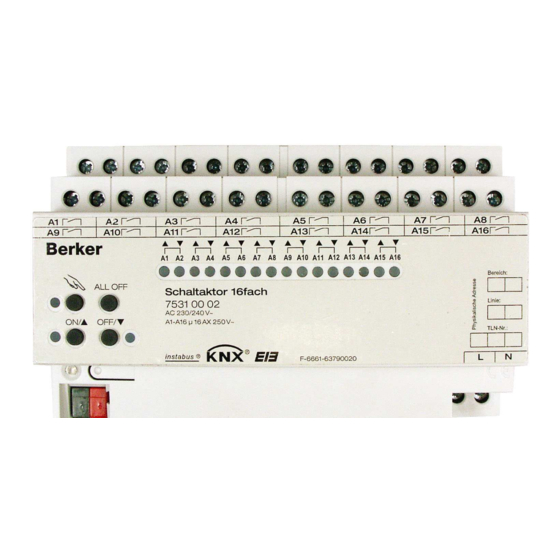
- Page 1 Switch/shutter actuator 8/4gang 16A RMD Technical Documentation 75318003 Switch/shutter actuator 16/8gang 16A 75310002 © Berker GmbH & Co KG 2007 Version: 04.04.2007 Part 5 (Subject to prior change) 75310002.doc Seite: 1 / 174...
-
Page 2: Table Of Contents
4.2.4.1 Description of channel-independent functions ..............45 4.2.4.2 Channel-oriented functional description ....................117 4.2.4.3 Delivery state ......................118 4.2.5 Parameters © Berker GmbH & Co KG 2007 Version: 04.04.2007 Part 5 (Subject to prior change) 75310002.doc Seite: 2 / 174... -
Page 3: Product Definition
The device is designed for being mounted on DIN rails in closed compact boxes or in power distributions in fixed installations in dry rooms. © Berker GmbH & Co KG 2007 Version: 04.04.2007... -
Page 4: Fitting, Electrical Connection And Operation
A minimum spacing of 4 mm must be ensured between bus wires and mains conductors. Do not open the device and do not operate it outside the scope of the technical specifications. © Berker GmbH & Co KG 2007 Version: 04.04.2007 Part 5 (Subject to prior change) 75310002.doc... -
Page 5: Device Components
LED flashing slowly: output controlled manually, LED flashing fast: output disabled by manual control. (6): Mains voltage terminal for power supply to the device electronics. © Berker GmbH & Co KG 2007 Version: 04.04.2007 Part 5 (Subject to prior change) 75310002.doc... -
Page 6: Fitting And Electrical Connection
A KNX/EIB data rail is not required. Observe the temperature range (-5 ° C ...+45 ° C) and ensure suffic ient cooling, if necessary. © Berker GmbH & Co KG 2007 Version: 04.04.2007 Part 5 (Subject to prior change) 75310002.doc... - Page 7 The connection of drives in the shutter mode or of loads in the switching mode is described on the following pages. © Berker GmbH & Co KG 2007 Version: 04.04.2007 Part 5 (Subject to prior change) 75310002.doc...
- Page 8 The device can be used with different phase conductors (L1, L2, L3). Venting louvers must be connected in such a way that they open in travel direction "UP - " and close in travel direction "DOWN – ". © Berker GmbH & Co KG 2007 Version: 04.04.2007 Part 5 (Subject to prior change) 75310002.doc...
- Page 9 Observe the admissible load ratings (cf. 'Technical data'). The device can be used with different phase conductors (L1, L2, L3). Do not connect three-phase AC motors to the actuator. © Berker GmbH & Co KG 2007 Version: 04.04.2007 Part 5 (Subject to prior change) 75310002.doc...
- Page 10 To remove the cap: Remove the cap by pressing the sides slightly and by pulling it out to the front (cf. Fig. 4.B). Fig. 4: Installing / removing the protective cap © Berker GmbH & Co KG 2007 Version: 04.04.2007 Part 5 (Subject to prior change) 75310002.doc...
-
Page 11: Commissioning
It is recommended to perform several time measurements and to take the average of these values. The travelling time can also be determined after commissioning with the ETS (bus operation). © Berker GmbH & Co KG 2007 Version: 04.04.2007 Part 5 (Subject to prior change) 75310002.doc... - Page 12 It is recommended to perform several time measurements and to take the average of these values. The slat-moving time can also be determined after commissioning with the ETS (bus operation). © Berker GmbH & Co KG 2007 Version: 04.04.2007 Part 5 (Subject to prior change) 75310002.doc...
- Page 13 The message is cancelled (inverted message value) as soon as a reference travel can be performed. In case of automatic end position detection, a travelling time must have been learnt beforehand. © Berker GmbH & Co KG 2007 Version: 04.04.2007 Part 5 (Subject to prior change) 75310002.doc...
-
Page 14: Operation
Further details concerning the manual mode, especially with respect to the possible parameter settings and the interaction with other functions of the switching/shutter actuator can be found in chapter 4. "Software description" of the present documentation. © Berker GmbH & Co KG 2007 Version: 04.04.2007 Part 5 (Subject to prior change) 75310002.doc... - Page 15 / : when ON, the LEDs indicate active travel movements in the shutter mode or closed relay contacts in the switching mode when controlled via the bus or manually. © Berker GmbH & Co KG 2007 Version: 04.04.2007 Part 5 (Subject to prior change) 75310002.doc...
- Page 16 With outputs parameterized for switching operation, only the status LED of the selected output is flashing. Mixed operation ios possible. After 5 s without a key-press, the actuator returns automatically to bus operation. © Berker GmbH & Co KG 2007 Version: 04.04.2007 Part 5 (Subject to prior change) 75310002.doc...
- Page 17 (direct operation, forced position / disabling function, safety or sun protection position) when the permanent manual mode is shut off. © Berker GmbH & Co KG 2007 Version: 04.04.2007...
- Page 18 The state indicator LEDs of the selected output A1...A8 / A16 are flashing fast. To unlock, proceed in the same way. An output that has been disabled manually can thereafter only be operated in the permanent manual mode. © Berker GmbH & Co KG 2007 Version: 04.04.2007 Part 5 (Subject to prior change) 75310002.doc...
-
Page 19: Technical Data
(cf. "Parameter description") Response to mains voltage failure: outputs are shut off (stop) Response to bus / mains voltage return: depending on parameterization (cf. "Parameter description") © Berker GmbH & Co KG 2007 Version: 04.04.2007 Part 5 (Subject to prior change) 75310002.doc... - Page 20 20 A Σ Σ max. max. 20 A 20 A Σ max. A1 A2 A3 ... 20 A An ... © Berker GmbH & Co KG 2007 Version: 04.04.2007 Part 5 (Subject to prior change) 75310002.doc Seite: 20 / 174...
- Page 21 Max. number per output (25.000 switching cycles): T8 lamps: QTP 2 x 58 W T5 lamps: QT-FH 4 x 14 W QT-FQ 2 x 54 W © Berker GmbH & Co KG 2007 Version: 04.04.2007 Part 5 (Subject to prior change) 75310002.doc Seite: 21 / 174...
-
Page 22: Software Information
Moreover, the preferred states of the relays in case of bus voltage failure or bus / mains voltage return and after ETS programming can be preset separately. © Berker GmbH & Co KG 2007 Version: 04.04.2007 Part 5 (Subject to prior change) 75310002.doc... - Page 23 Moreover, the preferred states of the relays in case of bus voltage failure or bus / mains voltage return and after ETS programming can be preset separately. © Berker GmbH & Co KG 2007 Version: 04.04.2007 Part 5 (Subject to prior change) 75310002.doc...
-
Page 24: Software "Switching, Shutter 2078X1 / 2080X1
• Timer functions (on-delay, off-delay, staircase lighting timer – optional with pre-warn function). • Integration into light-scenes possible: up to 8 internal scenes parameterizable per output (only for ETS3.0d). © Berker GmbH & Co KG 2007 Version: 04.04.2007 Part 5 (Subject to prior change) 75310002.doc... -
Page 25: Software Information
Unloading the application program The application program can be unloaded with the ETS. In this case, manual control as part of the application program is not available either. © Berker GmbH & Co KG 2007 Version: 04.04.2007 Part 5 (Subject to prior change) 75310002.doc... -
Page 26: Object Table
1-bit object for central actuation (long-time travel) of assigned shutter outputs. The polarity can be parameterized. Each communication object can be read out. For reading, the R-flag must be set. © Berker GmbH & Co KG 2007 Version: 04.04.2007 Part 5 (Subject to prior change) 75310002.doc... - Page 27 Every communication object can be read out. For readout, the R-flag must be set. Depending on parameterization, feedback objects are either actively transmitting (T-flag set) or passively readable (R-flag set). © Berker GmbH & Co KG 2007 Version: 04.04.2007 Part 5 (Subject to prior change) 75310002.doc...
- Page 28 1-byte object for recalling scenes or for storing new scene values. The number of outputs of the communication objects depends on the programmed device. Every communication object can be read out. For readout, the R-flag must be set. © Berker GmbH & Co KG 2007 Version: 04.04.2007 Part 5 (Subject to prior change) 75310002.doc...
- Page 29 Depending on parameterization, feedback objects are either actively transmitting (T-flag set) or passively readable (R-flag set). The object designations are independent of the selected channel definition. Every communication object can be read out. For readout, the R-flag must be set. © Berker GmbH & Co KG 2007 Version: 04.04.2007 Part 5 (Subject to prior change) 75310002.doc...
- Page 30 Depending on parameterization, feedback objects are either actively transmitting (T-flag set) or passively readable (R-flag set). Each communication object can be read out. For reading, the R-flag must be set. © Berker GmbH & Co KG 2007 Version: 04.04.2007 Part 5 (Subject to prior change) 75310002.doc...
- Page 31 The object designation varies with the type of curtain (blind, shutter / awning, venting louver). The object designations are independent of the selected channel definition. Each communication object can be read out. For reading, the R-flag must be set. © Berker GmbH & Co KG 2007 Version: 04.04.2007 Part 5 (Subject to prior change) 75310002.doc...
-
Page 32: Functional Description
After switching on of the mains voltage (bus voltage being on at this time), feedback telegrams are always transmitted without delay. © Berker GmbH & Co KG 2007 Version: 04.04.2007 Part 5 (Subject to prior change) 75310002.doc... - Page 33 The switching state set by a central function is not tracked in the "Switching" objects. After a bus voltage return or after programming with the ETS, the central function is always inactive (object value "0"). © Berker GmbH & Co KG 2007 Version: 04.04.2007 Part 5 (Subject to prior change) 75310002.doc...
- Page 34 After a bus voltage return or after programming with the ETS, the central function is always inactive (object value "0"). © Berker GmbH & Co KG 2007 Version: 04.04.2007 Part 5 (Subject to prior change) 75310002.doc...
- Page 35 In such applications, the centralized feedback can replace the 1-bit single feedback and thus reduce the bus load significantly. © Berker GmbH & Co KG 2007 Version: 04.04.2007 Part 5 (Subject to prior change) 75310002.doc...
- Page 36 No centralized feedback telegram is transmitted during an active delay after bus voltage return, even if a switching state changes during the delay. A blinking' output' (cf. "disabling function") will always be reported back as "switched on". © Berker GmbH & Co KG 2007 Version: 04.04.2007 Part 5 (Subject to prior change) 75310002.doc...
- Page 37 "Manual control during bus operation = enabled". For this reason, the disabling function, the status message and bus control disabling can only be configured in the above parameter setting. © Berker GmbH & Co KG 2007 Version: 04.04.2007 Part 5 (Subject to prior change) 75310002.doc...
- Page 38 (independent of priority) has been activated via the bus before or during manual control, the actuator re-executes these functions of a higher priority for the outputs concerned. © Berker GmbH & Co KG 2007 Version: 04.04.2007 Part 5 (Subject to prior change) 75310002.doc...
- Page 39 When an active manual control is terminated by a disable, the actuator will also transmit a "Manual control inactive" status telegram to the bus, if the status messaging function is enabled. © Berker GmbH & Co KG 2007 Version: 04.04.2007...
- Page 40 A locally activated bus control disable will not be reset in case of bus voltage failure or bus voltage return. Nor will the disable be reset by a mains voltage failure alone. A supply voltage failure (bus and mains voltage failure) will, however, deactivate the bus control disable. © Berker GmbH & Co KG 2007 Version: 04.04.2007 Part 5 (Subject to prior change) 75310002.doc...
- Page 41 "Frost alarm" Frost 1): Common monitoring time, different timers. Outputs 3...4 Fig. 10: Function diagram of the safety function © Berker GmbH & Co KG 2007 Version: 04.04.2007 Part 5 (Subject to prior change) 75310002.doc Seite: 41 / 174...
- Page 42 The wind alarm is completely deactivated for an assigned output only after all three objects are inactive ("0"). © Berker GmbH & Co KG 2007 Version: 04.04.2007...
- Page 43 The cycle time of the transmitters should be shorter than the monitoring time parameterized in the switching/shutter actuator in order to ensure that at least one telegram can be received during the monitoring time. © Berker GmbH & Co KG 2007 Version: 04.04.2007 Part 5 (Subject to prior change) 75310002.doc...
- Page 44 "Selection switching / shutter" page and are set with the ETS when the channel definition is changed. In this case, parameter settings or assignments of group adresses to objects can get lost. The channel definition should therefore be selected before paramerization of the actuator begins. © Berker GmbH & Co KG 2007 Version: 04.04.2007 Part 5 (Subject to prior change) 75310002.doc...
-
Page 45: Channel-Oriented Functional Description
(make or break contact) – all outputs are initialized with the switching state "off - 0" and that the feedback telegram is thus also adapted to this state. © Berker GmbH & Co KG 2007 Version: 04.04.2007... - Page 46 An active manual mode will be terminated by an ETS programming operation. After an ETS programming operation, the disabling functions and the forced-control positions are always deactivated. © Berker GmbH & Co KG 2007 Version: 04.04.2007 Part 5 (Subject to prior change) 75310002.doc...
- Page 47 (depending on the parameterization of the forced-control position functions). Active disabling or forced-control position functions are always deleted by a bus voltage failure and are inactive thereafter. © Berker GmbH & Co KG 2007 Version: 04.04.2007 Part 5 (Subject to prior change) 75310002.doc...
- Page 48 "Mode of operation" parameter. On return of bus voltage an active manual control will be terminated. Manual control is not possible in case of mains failures. © Berker GmbH & Co KG 2007 Version: 04.04.2007 Part 5 (Subject to prior change) 75310002.doc...
- Page 49 "switched on". switching status feedback telegrams are also transmitted for disabled outputs, for instance, if the outputs are re-adjusted by a manual operation. Switching state changes as a result of manual operation are also reported back to the bus. © Berker GmbH & Co KG 2007 Version: 04.04.2007 Part 5 (Subject to prior change) 75310002.doc...
- Page 50 The cycle time is defined centrally for all cyclical feedback telegrams on the parameter page "Switching outputs time settings" During an active delay after bus voltage return no feedback telegram will be transmitted even if a switching state changes. © Berker GmbH & Co KG 2007 Version: 04.04.2007 Part 5 (Subject to prior change) 75310002.doc...
- Page 51 In case of a logical operation function, a switching state newly received via the "Switching" object will be executed with a time delay as well. © Berker GmbH & Co KG 2007 Version: 04.04.2007 Part 5 (Subject to prior change) 75310002.doc...
- Page 52 The staircase function can moreover by enlarged by a separate ON-delay and by a pre-warning function. In acc. with DIN 18015-2, the pre-warning function is designed to warn a person in the staircase that the lights will go out shortly. © Berker GmbH & Co KG 2007 Version: 04.04.2007 Part 5 (Subject to prior change) 75310002.doc...
- Page 53 An ON-telegram received during the pre-warning time always retriggers the staircase lighting time independent of the "Staircase time retriggerable ?" parameter. © Berker GmbH & Co KG 2007 Version: 04.04.2007 Part 5 (Subject to prior change) 75310002.doc...
- Page 54 Set the parameter "Reaction to OFF-telegram" to "Ignore". OFF-telegrams received during the ON-phase of the staircase time will be rejected. The staircase time will be executed completely, if applicable with a pre-warning. © Berker GmbH & Co KG 2007 Version: 04.04.2007 Part 5 (Subject to prior change) 75310002.doc...
- Page 55 Interrupt 1. 2. 3. 4. output time pre-warn feedback (non inverted) time Fig.17: The pre-warning function of the staircase function © Berker GmbH & Co KG 2007 Version: 04.04.2007 Part 5 (Subject to prior change) 75310002.doc Seite: 55 / 174...
- Page 56 (independent of the "Staircase time retriggerable ?" parameter). The parameter "Reaction to OFF-telegram" is also evaluated during the pre-warning time so that an active pre-warning can be terminated prematurely by switching off. © Berker GmbH & Co KG 2007 Version: 04.04.2007 Part 5 (Subject to prior change) 75310002.doc...
- Page 57 A switching state set after bus or mains voltage return will be tracked in the feedback object as provided for in the "Mode of operation" parameter. © Berker GmbH & Co KG 2007 Version: 04.04.2007 Part 5 (Subject to prior change) 75310002.doc...
- Page 58 * = parameterizable as an option delay after cyclical Object bus voltage return transmission "centralized feedb." Fig. 18: Functional diagram of the scene function © Berker GmbH & Co KG 2007 Version: 04.04.2007 Part 5 (Subject to prior change) 75310002.doc Seite: 58 / 174...
- Page 59 When the actuator is put into operation for the first time, this parameter should be set to "Yes" so that the output is initialized with valid scene values. Otherwise, the values in the actuator are "0" (off) for all scenes. © Berker GmbH & Co KG 2007 Version: 04.04.2007 Part 5 (Subject to prior change) 75310002.doc...
- Page 60 "Ax – scenes" for each scene to "No". The storage function is deactivated for the scene in question. A storage telegram received via the "scene extension" object will be rejected. © Berker GmbH & Co KG 2007 Version: 04.04.2007 Part 5 (Subject to prior change) 75310002.doc...
- Page 61 Updates of the disabling object from "ON" to "ON" or from "OFF" to "OFF" show no reaction. The relay remains in the position last set, if applicable also set manually. An output disabled via the bus can still be operated by hand! © Berker GmbH & Co KG 2007 Version: 04.04.2007 Part 5 (Subject to prior change) 75310002.doc...
- Page 62 © Berker GmbH & Co KG 2007 Version: 04.04.2007...
- Page 63 ON" will cause the relay every time to switch the contact into the forced-control position. Updates from "Forced-control position OFF" to "Forced-control position OFF" remain without effect. An output under forced control from the bus can still be operated by hand! © Berker GmbH & Co KG 2007 Version: 04.04.2007 Part 5 (Subject to prior change) 75310002.doc...
- Page 64 20 s ago. Otherwise (T < 20 s), the forced-control position will not be activated on return of bus voltage and the "Behaviour after an ETS programing operation" executed. © Berker GmbH & Co KG 2007 Version: 04.04.2007 Part 5 (Subject to prior change) 75310002.doc...
- Page 65 "switching" input will directly reset this input when it is being set. Only if the logic operation object = "1", can the output adopt the logic state "1" after a new "1" has been received on the "Switching" input. © Berker GmbH & Co KG 2007 Version: 04.04.2007 Part 5 (Subject to prior change) 75310002.doc...
- Page 66 A mains voltage return does not affect the logic operation communication objects. The objects remain in the state last set, if the bus voltage was on without interruption. © Berker GmbH & Co KG 2007 Version: 04.04.2007 Part 5 (Subject to prior change) 75310002.doc...
- Page 67 Venting louvers must be connected to the outputs in such a way that they are opened in travel direction "up - " and closed in travel direction "down - ". An awning travels upwards when it is rolled up. © Berker GmbH & Co KG 2007 Version: 04.04.2007 Part 5 (Subject to prior change) 75310002.doc...
- Page 68 After programming with the ETS, the safety functions, the forced positions and the sun protection function are always deactivated. © Berker GmbH & Co KG 2007 Version: 04.04.2007 Part 5 (Subject to prior change) 75310002.doc...
- Page 69 In this state, the outputs are no longer selectable. Time functions (scene, sun protection and presence delays) are not interrupted, if only the mains voltage fails. © Berker GmbH & Co KG 2007 Version: 04.04.2007...
- Page 70 In case of bus or mains voltage failure, the current states of the forced position control (only in ETS 3.0d and onwards) or – if parameterized – also the slat offsets of the sun protection positions are stored as well. © Berker GmbH & Co KG 2007 Version: 04.04.2007 Part 5 (Subject to prior change) 75310002.doc...
- Page 71 The parameterized "Behaviour after bus or mains voltage return" will only be executed, if no forced position function is activated after bus voltage return. © Berker GmbH & Co KG 2007 Version: 04.04.2007 Part 5 (Subject to prior change) 75310002.doc...
- Page 72 If only the bus or the mains fails after an ETS download and is then restored, the actuator executes the "Behaviour after bus or mains voltage return". © Berker GmbH & Co KG 2007 Version: 04.04.2007 Part 5 (Subject to prior change) 75310002.doc...
- Page 73 The parameterized "Duration of short-time operation" should correspond for a blind to ca. ¼ of the complete slat moving time and for a shutter to the full time needed for opening the shutter segments. The short-time operation is always executed without travelling time extension. © Berker GmbH & Co KG 2007 Version: 04.04.2007 Part 5 (Subject to prior change) 75310002.doc...
- Page 74 (e.g. temperature, wind, etc.). © Berker GmbH & Co KG 2007 Version: 04.04.2007...
- Page 75 (0%) - slats completely closed (100%) - direct insolation max. shading Fig. 25: Type 2 - slatted blinds with oblique and horizontal slat position © Berker GmbH & Co KG 2007 Version: 04.04.2007 Part 5 (Subject to prior change) 75310002.doc...
- Page 76 Set the parameter "Change-over time for travel direction changes" on parameter page "Ax - Time settings" (x = number of output) to the required change-over interval. When the actuator is delivered ex factory, the change-over time is generally preset to 1 s. © Berker GmbH & Co KG 2007 Version: 04.04.2007 Part 5 (Subject to prior change) 75310002.doc...
- Page 77 = 5 s. The output will then lower the shutter for 5 s and (25 %) thus position the curtain at height of 25 %. © Berker GmbH & Co KG 2007 Version: 04.04.2007 Part 5 (Subject to prior change) 75310002.doc...
- Page 78 In case of mains failure, the drives will be stopped. Position approaches are also interrupted when the manual control mode is activated. © Berker GmbH & Co KG 2007 Version: 04.04.2007 Part 5 (Subject to prior change) 75310002.doc...
- Page 79 For each positioning movement, the desired blind position is referred to a slat position of 100 %. In the event of a slat re-positioning movement (0 to 100 %), the actuator will therefore report a blind position below the desired position. © Berker GmbH & Co KG 2007 Version: 04.04.2007 Part 5 (Subject to prior change) 75310002.doc...
- Page 80 The smaller the ratio between slat moving time and blind travelling time, the more precise the position approaches and the less marked the influence of the slat angle adjustment on the height of the blind. © Berker GmbH & Co KG 2007 Version: 04.04.2007...
- Page 81 If the reference travel is interrupted for instance by a short-time operation, the position is still unknown as before. A long-time travel into the lower end position activated via the corresponding communication object also calibrates the reference position. © Berker GmbH & Co KG 2007 Version: 04.04.2007 Part 5 (Subject to prior change) 75310002.doc...
- Page 82 The slat positioning command last received will only be executed after the blind position is reached. © Berker GmbH & Co KG 2007 Version: 04.04.2007 Part 5 (Subject to prior change) 75310002.doc...
- Page 83 This can be achieved for instance by a central raising command transmitted to the long-time object. © Berker GmbH & Co KG 2007 Version: 04.04.2007...
- Page 84 In case of unknown positions, the actuator automatically performs reference travels, if new positions are preset and if these positions are to be approached. As long as a position is unknown, the value of the feedback objects is "0". © Berker GmbH & Co KG 2007 Version: 04.04.2007 Part 5 (Subject to prior change) 75310002.doc...
- Page 85 No feedback telegram will be transmitted during a running delay, even if a position value changes during this delay. © Berker GmbH & Co KG 2007 Version: 04.04.2007...
- Page 86 In case of blinds operation, any position change of the blind within the limits of the slat adjustment (0 to 100 %) does not launch a travel movement and therefore no change of the feedback position data either. © Berker GmbH & Co KG 2007 Version: 04.04.2007...
- Page 87 This means that if a drive is blocked or already in its end position, the value reported back does not correspond to the actual state of the travel movement. © Berker GmbH & Co KG 2007 Version: 04.04.2007 Part 5 (Subject to prior change) 75310002.doc...
- Page 88 Automatic transmission after bus voltage return will take place only if an internal change of the object state has occurred (caused, for instance, by a reference travel during manual control). © Berker GmbH & Co KG 2007 Version: 04.04.2007 Part 5 (Subject to prior change) 75310002.doc...
- Page 89 Automatic transmission after bus voltage return will take place only if the drive starts moving on return of bus voltage or if there has been a change of the travel movement caused by the bus failure. © Berker GmbH & Co KG 2007 Version: 04.04.2007...
- Page 90 At the end of a forced position or of a manual control, the safety reaction is re-executed if an assigned safety alarm is still active. © Berker GmbH & Co KG 2007 Version: 04.04.2007...
- Page 91 Set the parameter "Behaviour in case of ..." to "stop" At the beginning of the alarm, the actuator switches the relays of the output to "stop" and locks the output. A travel movement, if any, will be interrupted. © Berker GmbH & Co KG 2007 Version: 04.04.2007 Part 5 (Subject to prior change) 75310002.doc...
- Page 92 If a sun protection function is activated (independent of the preset priority with respect to direct operation), it will be also executed. © Berker GmbH & Co KG 2007 Version: 04.04.2007 Part 5 (Subject to prior change) 75310002.doc...
- Page 93 © Berker GmbH & Co KG 2007 Version: 04.04.2007...
- Page 94 (if enabled in case of bus failure), even if there is no bus voltage. © Berker GmbH & Co KG 2007 Version: 04.04.2007 Part 5 (Subject to prior change) 75310002.doc...
- Page 95 ** = optional only with "blind" mode of operation Object "Long-time" / "Central"* Object "Short-time" Object "Scene" Object "Position" Fig. 33: Function diagram illustrating the sun protection © Berker GmbH & Co KG 2007 Version: 04.04.2007 Part 5 (Subject to prior change) 75310002.doc Seite: 95 / 174...
- Page 96 However, the position data or offsets received are stored internally so that the new positions will be approached on reactivation of the sun protection. © Berker GmbH & Co KG 2007 Version: 04.04.2007 Part 5 (Subject to prior change) 75310002.doc...
- Page 97 © Berker GmbH & Co KG 2007 Version: 04.04.2007...
- Page 98 In the "Blinds" mode of operation, the setting "fixed position" can be selected separately for the height of the blind and for the slat position. For this reason, the ETS adapts the parameter selection and enlarges the setting options in this mode of operation. © Berker GmbH & Co KG 2007 Version: 04.04.2007 Part 5 (Subject to prior change) 75310002.doc...
- Page 99 The position data last received are not lost in a bus voltage failure (mains voltage on). © Berker GmbH & Co KG 2007 Version: 04.04.2007 Part 5 (Subject to prior change) 75310002.doc...
- Page 100 "Blind" mode of operation: A terminated reference travel of for the height of the blind synchronizes at the same time also the slat position. © Berker GmbH & Co KG 2007 Version: 04.04.2007 Part 5 (Subject to prior change) 75310002.doc...
- Page 101 Offset: +30% Offset: +30% 100% Fig. 34: Functional principle of slat offset (example showing slat type 1 / slat type 2 identical) © Berker GmbH & Co KG 2007 Version: 04.04.2007 Part 5 (Subject to prior change) 75310002.doc Seite: 101 / 174...
- Page 102 (return of bus or mains voltage, if both voltages were off beforehand). After the initialization, the offset value parameterized in the ETS will be used again. © Berker GmbH & Co KG 2007 Version: 04.04.2007 Part 5 (Subject to prior change) 75310002.doc...
- Page 103 The slat offset has no influence on the behaviour of an output at the end of a shading phase (end of sunshine/shading). © Berker GmbH & Co KG 2007 Version: 04.04.2007 Part 5 (Subject to prior change) 75310002.doc...
- Page 104 Known slat positions will also be tracked as described. This is also the case, when the height of the blind is unknown. Long-time travel movements (travels without position preset) will, however, always be tracked. © Berker GmbH & Co KG 2007 Version: 04.04.2007 Part 5 (Subject to prior change) 75310002.doc...
- Page 105 Sun protection application examples The present chapter describes different applications of the sun protection function of the switching/shutter actuator in combination with the Berker KNX/EIB Weather station (order no. 7541 40 03) and the combination sensor (order no. 7590 00 57).
- Page 106 … [shading control facades 1-4] sunshine/shading facade (1 bit) (1 bit) Fig. 36: Programming of the communication objects for application example II © Berker GmbH & Co KG 2007 Version: 04.04.2007 Part 5 (Subject to prior change) 75310002.doc...
- Page 107 [individual control facades …] slat position (1 byte) (1 byte) Fig. 37: Programming of the communication objects for application example III © Berker GmbH & Co KG 2007 Version: 04.04.2007 Part 5 (Subject to prior change) 75310002.doc Seite: 107 / 174...
- Page 108 [individual control facades …] slat position (1 byte) (1 byte) Fig. 38: Programming of the communication objects for application example IV © Berker GmbH & Co KG 2007 Version: 04.04.2007 Part 5 (Subject to prior change) 75310002.doc Seite: 108 / 174...
- Page 109 ...[individual contral facades 1-4] blind position (1 byte) (1 byte) Fig. 39: Programming of the communication objects for application example V © Berker GmbH & Co KG 2007 Version: 04.04.2007 Part 5 (Subject to prior change) 75310002.doc Seite: 109 / 174...
- Page 110 The scene recall is nevertheless stored internally so that the scene positions last recalled can be tracked at the end of a higher-ranking function. © Berker GmbH & Co KG 2007 Version: 04.04.2007...
- Page 111 If the same scene number is parameterized for several scenes, only the scene with the lowest internal scene number (1...8) will be addressed. The other internal scenes will be ignored in this case. © Berker GmbH & Co KG 2007 Version: 04.04.2007...
- Page 112 The data are stored only if the mains voltage was available beforehand during at least 20 seconds after the last reset (storage capacitors sufficiently charged for storage purposes). The data will not be stored, if the position data are unknown. © Berker GmbH & Co KG 2007 Version: 04.04.2007 Part 5 (Subject to prior change) 75310002.doc...
- Page 113 – if enabled in case of bus failure – even if there is no bus voltage. The current state of the forced position function will be stored in case of bus or mains voltage failure. © Berker GmbH & Co KG 2007 Version: 04.04.2007...
- Page 114 The parameterized behaviour will not be executed either if the forced position function is terminated by a preset on return of bus voltage. In this case, the preset "Behaviour after bus/mains voltage return" will be executed. © Berker GmbH & Co KG 2007 Version: 04.04.2007 Part 5 (Subject to prior change) 75310002.doc...
- Page 115 "Behaviour after bus/mains voltage return. After programming of the application or of the parameters with the ETS, the forced position is always cancelled. © Berker GmbH & Co KG 2007 Version: 04.04.2007 Part 5 (Subject to prior change) 75310002.doc...
- Page 116 Set the parameter "Fabric-stretching function" to "enabled". Parameter page "Ax – Fabric-stretching" is enabled and the fabric-stretching function is activated. Fabric-stretching cannot be parameterized in the blind or louver modes of operation. © Berker GmbH & Co KG 2007 Version: 04.04.2007 Part 5 (Subject to prior change) 75310002.doc...
-
Page 117: Delivery State
– Break during travel direction changeover 1 s – Response to bus voltage failure: no reaction – Behaviour on return of bus or mains voltage: stop © Berker GmbH & Co KG 2007 Version: 04.04.2007 Part 5 (Subject to prior change) 75310002.doc... -
Page 118: Parameters
Central object polarity This parameter defines the polarity of the 0 = UP; 1 = DOWN central object. 0 = DOWN; 1 = UP © Berker GmbH & Co KG 2007 Version: 04.04.2007 Part 5 (Subject to prior change) 75310002.doc... -
Page 119: Berker Gmbh & Co Kg
Example: Blinking rate = 1 s 1 s off 1 s on 1 s off ... © Berker GmbH & Co KG 2007 Version: 04.04.2007 Part 5 (Subject to prior change) 75310002.doc Seite: 119 / 174... - Page 120 Setting the cycle time minutes. 0… 2 ...59 Seconds (10...59) Setting the cycle time seconds. 10 ...59 Default setting: 2 minutes 10 seconds © Berker GmbH & Co KG 2007 Version: 04.04.2007 Part 5 (Subject to prior change) 75310002.doc Seite: 120 / 174...
- Page 121 (setting: "disabled"), any programmed assignment of individual shutter outputs to the frost alarm is not operational. © Berker GmbH & Co KG 2007 Version: 04.04.2007 Part 5 (Subject to prior change) 75310002.doc Seite: 121 / 174...
- Page 122 The safety alarm enabling parameters and the priority parameter is only visible when the safety functions are enabled. © Berker GmbH & Co KG 2007 Version: 04.04.2007 Part 5 (Subject to prior change) 75310002.doc Seite: 122 / 174...
- Page 123 0 ...23 This parameter is used for programming the Hours (0...23) rain alarm monitoring time. Sets the monitoring time hours. © Berker GmbH & Co KG 2007 Version: 04.04.2007 Part 5 (Subject to prior change) 75310002.doc Seite: 123 / 174...
- Page 124 The cycle time of the transmitter should be less than half the parameterized monitoring time of the actuator. The times can only be set, if frost alarm monitoring is activated. © Berker GmbH & Co KG 2007 Version: 04.04.2007 Part 5 (Subject to prior change) 75310002.doc...
- Page 125 The status will be actively transmitted to the bus ("0") after bus voltage return only if a manual control was terminated by such return of voltage. © Berker GmbH & Co KG 2007 Version: 04.04.2007 Part 5 (Subject to prior change) 75310002.doc...
- Page 126 Disabling by means of manual control is only permitted if this parameter is set to "yes" © Berker GmbH & Co KG 2007 Version: 04.04.2007 Part 5 (Subject to prior change) 75310002.doc...
- Page 127 Output 15 and combined outputs A15 and A16. output 16 * 2 x switching output *: Only at switching/shutter actuator 8/16gang © Berker GmbH & Co KG 2007 Version: 04.04.2007 Part 5 (Subject to prior change) 75310002.doc Seite: 127 / 174...
- Page 128 "Behaviour after bus/mains voltage return" will be executed instead. © Berker GmbH & Co KG 2007 Version: 04.04.2007 Part 5 (Subject to prior change) 75310002.doc...
- Page 129 This parameter is only visible, if "Behaviour in case of bus voltage failure" is set to "approach position". This parameter is visible only in the 'Shutter/awning' mode of operation. © Berker GmbH & Co KG 2007 Version: 04.04.2007 Part 5 (Subject to prior change) 75310002.doc...
- Page 130 The parameterized behaviour will only be adopted, if no forced position is activated after bus voltage return. © Berker GmbH & Co KG 2007 Version: 04.04.2007 Part 5 (Subject to prior change) 75310002.doc...
- Page 131 (completely open position). 10 % 12.5 % This parameter is only visible, when the automatic end position detection is not deactivated. © Berker GmbH & Co KG 2007 Version: 04.04.2007 Part 5 (Subject to prior change) 75310002.doc Seite: 131 / 174...
- Page 132 The travelling time parameters are only visible when the automatic end position detection is not enabled. These parameters are visible only in the 'Blind' mode of operation. © Berker GmbH & Co KG 2007 Version: 04.04.2007 Part 5 (Subject to prior change) 75310002.doc...
- Page 133 (downward direction) must be determined. Sets the minutes of the slat moving time. © Berker GmbH & Co KG 2007 Version: 04.04.2007 Part 5 (Subject to prior change) 75310002.doc...
- Page 134 (only in ETS3.0d and enabled, the corresponding parameters will be enabled onwards) displayed under "Ax - scenes" and the necessary object enabled. © Berker GmbH & Co KG 2007 Version: 04.04.2007 Part 5 (Subject to prior change) 75310002.doc Seite: 134 / 174...
- Page 135 The central function is supposed to have been enabled under "General". The assignment has otherwise no effect on the shutter output. The output is not assigned to the central function. © Berker GmbH & Co KG 2007 Version: 04.04.2007 Part 5 (Subject to prior change) 75310002.doc...
- Page 136 The communication flags of the object are automatically set by the ETS according to the setting. This parameter is visible only in the 'Shutter/awning' mode of operation. © Berker GmbH & Co KG 2007 Version: 04.04.2007 Part 5 (Subject to prior change) 75310002.doc...
- Page 137 The communication flags of the object are automatically set by the ETS according to the setting. This parameter is visible only in the 'Blind' mode of operation. © Berker GmbH & Co KG 2007 Version: 04.04.2007 Part 5 (Subject to prior change) 75310002.doc...
- Page 138 The communication flags of the object are automatically set by the ETS according to the setting. This parameter is visible only in the 'Shutter/awning' mode of operation. © Berker GmbH & Co KG 2007 Version: 04.04.2007 Part 5 (Subject to prior change) 75310002.doc...
- Page 139 'Read' request. The communication flags of the object are automatically set by the ETS according to the setting. © Berker GmbH & Co KG 2007 Version: 04.04.2007 Part 5 (Subject to prior change) 75310002.doc Seite: 139 / 174...
- Page 140 The delay time is parameterized under "General". This parameter is only visible in case of an actively transmitting feedback object. © Berker GmbH & Co KG 2007 Version: 04.04.2007 Part 5 (Subject to prior change) 75310002.doc...
- Page 141 This parameter is only visible, if the output has been assigned to at least one wind alarm. © Berker GmbH & Co KG 2007 Version: 04.04.2007 Part 5 (Subject to prior change) 75310002.doc...
- Page 142 An assignment to the alarms is only possible when the safety functions and the alarms themselves are enabled under "Shutter outputs safety". © Berker GmbH & Co KG 2007 Version: 04.04.2007 Part 5 (Subject to prior change) 75310002.doc...
- Page 143 A travel movement in progress, if any, will be interrupted. stop This parameter is only visible, if the output has been assigned to the frost alarm. © Berker GmbH & Co KG 2007 Version: 04.04.2007 Part 5 (Subject to prior change) 75310002.doc...
- Page 144 Direct operation will be executed when a sun protection function is active. © Berker GmbH & Co KG 2007 Version: 04.04.2007 Part 5 (Subject to prior change) 75310002.doc...
- Page 145 "Sunshine / shading facade" of the sun no sunshine = 0 protection. sunshine = 0; no sunshine = 1 © Berker GmbH & Co KG 2007 Version: 04.04.2007 Part 5 (Subject to prior change) 75310002.doc Seite: 145 / 174...
- Page 146 Presetting: 30 seconds A time setting of "0" in the parameters deactivates the respective delay time. In this case, the state of shading is evaluated immediately. © Berker GmbH & Co KG 2007 Version: 04.04.2007 Part 5 (Subject to prior change) 75310002.doc...
- Page 147 This parameter is visible only in the 'Blind' mode of operation. © Berker GmbH & Co KG 2007 Version: 04.04.2007 Part 5 (Subject to prior change) 75310002.doc Seite: 147 / 174...
- Page 148 / awning position preset by a separate object and thus variable. variable This parameter is visible only in the "Shutter / awning" mode of operation. © Berker GmbH & Co KG 2007 Version: 04.04.2007 Part 5 (Subject to prior change) 75310002.doc...
- Page 149 This parameter is only visible, if the parameter "Reaction at the beginning of sunshine / shading" is set to "internal scene recall". © Berker GmbH & Co KG 2007 Version: 04.04.2007 Part 5 (Subject to prior change) 75310002.doc...
- Page 150 This parameter is visible only in the "Shutter / awning" mode of operation. © Berker GmbH & Co KG 2007 Version: 04.04.2007 Part 5 (Subject to prior change) 75310002.doc...
- Page 151 If no synchronizing movement is forced (setting: "no"), the actuator performs a reference travel only once after return of the power supply. © Berker GmbH & Co KG 2007 Version: 04.04.2007 Part 5 (Subject to prior change) 75310002.doc...
- Page 152 "Offset as parameterized" or to "Offset as parameterized and via object". This parameter is visible only in the 'Blind' mode of operation. © Berker GmbH & Co KG 2007 Version: 04.04.2007 Part 5 (Subject to prior change) 75310002.doc...
- Page 153 "Offset with fixed and variable slat position" is set to "offset as parameterized and via object". This parameter is visible only in the 'Blind' mode of operation. © Berker GmbH & Co KG 2007 Version: 04.04.2007 Part 5 (Subject to prior change) 75310002.doc...
- Page 154 The behaviour preset in this parameter will only be executed, if no function with a higher priority (e.g. safety) is activated at the time of shading. © Berker GmbH & Co KG 2007 Version: 04.04.2007 Part 5 (Subject to prior change) 75310002.doc...
- Page 155 (1...8) value is dependent on This parameter is visible only in the 'Blind' the scene (1...8). mode of operation. © Berker GmbH & Co KG 2007 Version: 04.04.2007 Part 5 (Subject to prior change) 75310002.doc Seite: 155 / 174...
- Page 156 X = depending on the the extension object on reception of a storage scene (1...8) telegram. If "no" is selected, the storage telegrams are rejected. © Berker GmbH & Co KG 2007 Version: 04.04.2007 Part 5 (Subject to prior change) 75310002.doc...
- Page 157 The forced-position parameters are only visible, if the parameter "Forced-position function" under "Ax - Enabled functions" is set to "enabled". © Berker GmbH & Co KG 2007 Version: 04.04.2007 Part 5 (Subject to prior change) 75310002.doc Seite: 157 / 174...
- Page 158 Presetting: 1 second The time for the fabric-stretching movement must be selected shorter than the travelling time of the shutter/awning! © Berker GmbH & Co KG 2007 Version: 04.04.2007 Part 5 (Subject to prior change) 75310002.doc Seite: 158 / 174...
- Page 159 "Behaviour after bus voltage return" will be executed - © Berker GmbH & Co KG 2007 Version: 04.04.2007 Part 5 (Subject to prior change) 75310002.doc...
- Page 160 The parameterized behaviour will only be adopted, if no forced control is activated after bus voltage return. © Berker GmbH & Co KG 2007 Version: 04.04.2007 Part 5 (Subject to prior change) 75310002.doc...
- Page 161 - The delay time is parameterized under "General". This parameter is visible as an active message object only if feedback is enabled. © Berker GmbH & Co KG 2007 Version: 04.04.2007 Part 5 (Subject to prior change) 75310002.doc...
- Page 162 (transmission only in case of changes) This parameter is visible as an active message object only if feedback is enabled. © Berker GmbH & Co KG 2007 Version: 04.04.2007 Part 5 (Subject to prior change) 75310002.doc...
- Page 163 Minutes (0...59) 0 ...59 Setting the ON-delay minutes. Seconds (0...59) 0… 30 ...59 Setting the ON-delay seconds. Presetting: 30 seconds © Berker GmbH & Co KG 2007 Version: 04.04.2007 Part 5 (Subject to prior change) 75310002.doc Seite: 163 / 174...
- Page 164 (setting "no"). The OFF-delay parameters are only visible, if the parameter "Selection of time delay" is set to "OFF-delay" or to "ON- and OFF-delay". © Berker GmbH & Co KG 2007 Version: 04.04.2007 Part 5 (Subject to prior change) 75310002.doc...
- Page 165 The ON-delay parameterized under this item is independent of the other time functions of the actuator. It only acts on the staircase function and not on the "Switching" object. © Berker GmbH & Co KG 2007 Version: 04.04.2007 Part 5 (Subject to prior change) 75310002.doc...
- Page 166 This parameter defines how often the output is 1… 3 ...10 (1...10) to switch off within the pre-warning time. i.e. how many pre-warnings will be generated. © Berker GmbH & Co KG 2007 Version: 04.04.2007 Part 5 (Subject to prior change) 75310002.doc...
- Page 167 ("Number of pre-warnings" + "Time for pre- warning interruptions") must not be chosen longer than the pre-warning time itself. Otherwise risk of malfunctions. © Berker GmbH & Co KG 2007 Version: 04.04.2007 Part 5 (Subject to prior change) 75310002.doc...
- Page 168 This parameter defines the scene number (1...64) which is used to address the internal scene (1...8) scene. A setting of "0" deactivates the corresponding scene. © Berker GmbH & Co KG 2007 Version: 04.04.2007 Part 5 (Subject to prior change) 75310002.doc Seite: 168 / 174...
- Page 169 X = depending on the scene stored internally via the extension object during (1...8) reception of a scene storage telegram. If "no" is selected, the storage telegrams are rejected. © Berker GmbH & Co KG 2007 Version: 04.04.2007 Part 5 (Subject to prior change) 75310002.doc...
- Page 170 An output disabled via the bus can still be operated by hand! This parameter is only visible, if the parameter "Selection of supplementary function is set to "disabling function". © Berker GmbH & Co KG 2007 Version: 04.04.2007 Part 5 (Subject to prior change) 75310002.doc...
- Page 171 "Switching" object (no evaluations of time functions). This parameter is only visible, if the parameter "Selection of supplementary function is set to "disabling function". © Berker GmbH & Co KG 2007 Version: 04.04.2007 Part 5 (Subject to prior change) 75310002.doc...
- Page 172 "Switching" object (no evaluations of time functions). © Berker GmbH & Co KG 2007 Version: 04.04.2007 Part 5 (Subject to prior change) 75310002.doc...
- Page 173 "1" has been received on the "Switching" input. This parameter is only visible, if the parameter "Logic operation function ? is set to "yes". © Berker GmbH & Co KG 2007 Version: 04.04.2007 Part 5 (Subject to prior change) 75310002.doc...
- Page 174 ETS 1 (ON) programming. This parameter is only visible, if the parameter "Logic operation function ? is set to "yes". © Berker GmbH & Co KG 2007 Version: 04.04.2007 Part 5 (Subject to prior change) 75310002.doc Seite: 174 / 174...
Need help?
Do you have a question about the 75318003 and is the answer not in the manual?
Questions and answers