
Related Manuals for Workhorse Powerhouse Quartz 2608


Summary of Contents for Workhorse Powerhouse Quartz 2608
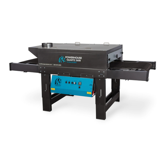
- Page 1 Owner’s Manual Powerhouse Quartz Dryer 3730 E. Southern Avenue, Phoenix, AZ 85040 USA 800-778-8779 Workhorseproducts.com...
-
Page 2: Table Of Contents
Table of Contents I. Introduction …………..…………………………...………………….……….…….……….. 3 II. Specifications …..……………..………………………...………….………..………….…. 4 III. Parts for Assembly …..……………..……………………….………………..….………. 5 IV. Safety Procedures ..………………………..…………………………..…….…...…… 6 V. Assembly Step 1: Leveling the Dryer and Installing the Legs ……….………….……… 7 Step 2: Attaching the Support Struts ……….……………………………..……. 10 Step 3: Attaching the Outfeed ……….………………..……………………..……. -
Page 3: Introduction
We will not be responsible for damages that occur during transportation. If there are damages immediately notify the driver, file a claim with the carrier and call Workhorse Products. The Importance of the Owner’s Manual: The purpose of the Owner’s Manual is to familiarize you with the parts and operations of the Powerhouse... -
Page 4: Specifications
Specifications PQ-2608 Belt Size: 26” x 8’ Production Capacity: 200-300/hr. Dimensions: 96”x 41”x 32” PQ-3011 Belt Size: 30” x 11’ Production Capacity: 400-500/hr. Dimensions: 132”x 41”x 32” PQ-5208 Belt Size: 52” x 8’ Production Capacity: 400-500/hr. Dimensions: 96” x 60” x 32” PQ-4013 Belt Size: 40”... -
Page 5: Parts For Assembly
Parts for Assembly QTY Description Part Number QTY Description Part Number Dryer Body Pre-Assembled Cross Braces 2608 Belt (2608) 20936 Reflectors 82118 Treading Pin 99-2375 Flange Nuts 42-FLG-3125-10 Hex HD Bolt (1/4-20” x 41-HB-250-95 Hex Bolt (1/4-20x 41-HB-250-15 2-1/2”) 1/2”) Lock Washer 43-LOK-250-30 Hex Bolt (5/16-... -
Page 6: Safety Procedures
Safety Procedures WARNING! RISK OF ELECTRICAL SHOCK! Turn ALL power to unit OFF before service. All service should be done by or under the supervision of a trained technician 1. For your safety, do not store or use gasoline or other flammable vapors and liquids in the vicinity (at least 3’ (1 Meter)) of this or any other appliance. -
Page 7: Assembly
Assembly Step 1: Leveling the dryer and installing the legs. Tools needed: Parts needed: 8 x Flat Washers 9/16” Socket Dryer Base 12 x Hex Bolts (5/16- Wrench 18” x 3/4”) 8 x Lock Washers ... - Page 8 Assembly Step 1 (Continued): Leveling the dryer. 5. At this point, only one side of the dryer will be 4. With the side of the dryer still lifted, tighten the bolt leveled. Just like steps 1-2, insert a bolt and nut and nut for the other leg.
- Page 9 Assembly Step 1 (Continued): Installing the legs. 9. Tighten a 5/16” flange nut onto the other side of 8. Insert a 1/2” washer, lock washer and hex bolt the bolt located inside of the dryer. Tighten the bolt (5/16-18”x 3/4”) into the side panel on the side of and nut with a socket wrench and wrench.
-
Page 10: Step 2: Attaching The Support Struts
Assembly Step 2: Attaching the support struts. Tools needed: Parts needed: 4 x Lock Washers 7/16” Wrench 2 x Support Struts 4 x Flat Washers 7/16” Socket 4 x Hex Bolts (5/16-18” x 3/4”) ... -
Page 11: Step 3: Attaching The Outfeed
Assembly Step 3: Attaching the outfeed. Parts needed: Tools needed: Outfeed Arm 7/16” Socket Wrench Hex Bolt (1/4-20 x 1/2”) 8 x Flat Washers 1. The outfeed arm (with the belt motor) belongs on the left side of the dryer. With another person, lift the arm and slide it into the dryer while aligning the four holes. -
Page 12: Step 4: Attaching The Infeed
Assembly Step 4: Attaching the infeed. Tools needed: Parts needed: 7/16” Socket Infeed Arm Wrench 8 x Hex Boles (1/4-20 x 1/2”) 8 x Flat Washers 1. The infeed arm (without the belt motor) belongs on the right side of the dryer. -
Page 13: Step 5: Installing The Belt
Assembly Step 5: Installing the belt. Parts needed: Belt Threading Pin 2. On the outfeed side, take the other end of the belt and 1. Thread the belt over the top of the outfeed roller and thread it under the outfeed roller and under the lower cross over the upper cross brace. -
Page 14: Step 6: Adjusting The Belt Tracking System
Assembly Step 6: Adjusting the belt tracking system. After the belt is centered on the rubber portion of the rollers, evenly adjust the tension bolts on every corner of the dryer to tighten the belt until it can be deflected by about 2 inches. Turn the dryer on and set the belt speed to 35%, as the belt moves make small adjustments to maintain the belt to be in the center of the rollers. -
Page 15: Step 7: Installing The Reflectors
Assembly Step 7: Installing the reflectors. Parts Needed: Tools Needed: 6 x Heat Reflectors 7/16” Socket Wrench 8 x Hex HD Bolt (1/4-20” x 2-1/2”) 8 x Flat Washers 1. With another person, lift the covers 2. -
Page 16: Step 8: Connecting To The Engine
Assembly Step 8: Connecting to the engine. 1. Connect the wire of the belt motor to the wire of the engine. Congratulations! The Powerhouse Quartz Dryer is now fully assembled! The size and specifications of the electrical connections made during installation MUST BE DETERMINED BY A LICENSED ELECTRICIAN. -
Page 17: Elements
Elements The quartz elements are installed using a ring terminal system. Fasten the elements securely to the buss bars using KEPS nuts as shown in Image 1. Image 2 shows the opposite side of the elements, mounted in a similar manner. Image 2 Image 1 When installing new elements it may be necessary to adjust the buss bar spacing. -
Page 18: Controls
The surface temperature of the garments may be significantly higher than the actual oven chamber tempera- ture. Workhorse Products carries a non contact infrared digital thermometer to accurately measure the surface tem- perature of your garments. Please call customer service today for price and availability! 3730 E. -
Page 19: Recirculation System
Workhorse Products recommends performing this routine maintenance every three to six months to maintain optimum performance of your dryer. 3730 E. Southern Avenue, Phoenix, AZ 85040 USA 800-778-8779 Workhorseproducts.com... -
Page 20: Ventilation
Please call Workhorse Products Customer Service today for price and availability! 3730 E. Southern Avenue, Phoenix, AZ 85040 USA 800-778-8779 Workhorseproducts.com... -
Page 21: Temperature Control Programming
Temp. Control Programming 3730 E. Southern Avenue, Phoenix, AZ 85040 USA 800-778-8779 Workhorseproducts.com... - Page 22 Temp. Control Programming 3730 E. Southern Avenue, Phoenix, AZ 85040 USA 800-778-8779 Workhorseproducts.com...
-
Page 23: Wiring Diagram
Wiring Diagram 3730 E. Southern Avenue, Phoenix, AZ 85040 USA 800-778-8779 Workhorseproducts.com... - Page 24 Wiring Diagram 3730 E. Southern Avenue, Phoenix, AZ 85040 USA 800-778-8779 Workhorseproducts.com...
- Page 25 Wiring Diagram 3730 E. Southern Avenue, Phoenix, AZ 85040 USA 800-778-8779 Workhorseproducts.com...
- Page 26 Wiring Diagram 3730 E. Southern Avenue, Phoenix, AZ 85040 USA 800-778-8779 Workhorseproducts.com...
- Page 27 Wiring Diagram 3730 E. Southern Avenue, Phoenix, AZ 85040 USA 800-778-8779 Workhorseproducts.com...
- Page 28 Wiring Diagram 3730 E. Southern Avenue, Phoenix, AZ 85040 USA 800-778-8779 Workhorseproducts.com...
- Page 29 Wiring Diagram 3730 E. Southern Avenue, Phoenix, AZ 85040 USA 800-778-8779 Workhorseproducts.com...
- Page 30 Wiring Diagram 3730 E. Southern Avenue, Phoenix, AZ 85040 USA 800-778-8779 Workhorseproducts.com...
- Page 31 Wiring Diagram 3730 E. Southern Avenue, Phoenix, AZ 85040 USA 800-778-8779 Workhorseproducts.com...
- Page 32 Wiring Diagram 3730 E. Southern Avenue, Phoenix, AZ 85040 USA 800-778-8779 Workhorseproducts.com...
- Page 33 Wiring Diagram 3730 E. Southern Avenue, Phoenix, AZ 85040 USA 800-778-8779 Workhorseproducts.com...
-
Page 34: Limited Warranty
Equipment manufactured or sold by Workhorse Products is warranted against defects in workmanship and materials for a period of one year from receipt by cus- tomer. All warranties initiate from date of shipment to original customer. Replacement parts are covered for the term of the equipment warranty period.
Need help?
Do you have a question about the Powerhouse Quartz 2608 and is the answer not in the manual?
Questions and answers