
Related Manuals for BARIX Barionet


Summary of Contents for BARIX Barionet
- Page 1 HANDS-ON TRAINING GUIDE B A R I O N E T Document Name: Barionet Hands-on Training Guide Document ID: 20131017SG2 Document Date: 17. Oct. 2013 Document Version: 1.31 Firmware name: Barionet FW Release Date: Package Name:...
-
Page 2: Table Of Contents
4.1 Converting analog register value..............23 4.2 Converting temperature register value............23 5 How to connect extension units to the Barionet....24 5.1 Wiring........................25 5.1.1 Barionet50....................25 5.1.2 Barionet100..................... 25 BARIX AG | 17. Oct. 2013 | Barionet Hands-on Training Guide | Page 2/38... - Page 3 6.1.2 SNMP Trap....................32 6.2 Modbus Scanner from Chipkin Automation Systems.......33 6.3 Serial Redirector software from Lantronix Inc...........36 7 Important Barionet help links..........37 8 Legal Information..............38 BARIX AG | 17. Oct. 2013 | Barionet Hands-on Training Guide | Page 3/38...
-
Page 4: Introduction
IO and the other interfaces practically. It describes procedures on a very low level, so that also Barionet beginners and users with limited electrical or IT-knowledge can follow. BARIX AG | 17. Oct. 2013 | Barionet Hands-on Training Guide | Page 4/38... -
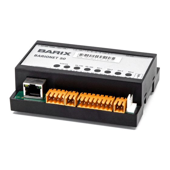
Page 5: Product Features (Interfaces)
4 digital outputs 2 relays (digital, max. 5A at 240VAC) 1 serial RS232 interface 1 serial RS485 interface 1 Dallas One-wire interface 1 Wiegand interface 1 network interface BARIX AG | 17. Oct. 2013 | Barionet Hands-on Training Guide | Page 5/38... -
Page 6: How To Use The Hardware Interfaces
Barionet´s hardware interfaces (like inputs, outputs or relays). 2.1 How to use the digital inputs ? A digital input of the Barionet knows only two states : ON (1) or OFF (0) On the Barionet100 the input polarity can be changed in the configuration setup (under “IO”). -
Page 7: Connecting The Input Directly To Input Ground
For that connect any digital input to the digital ground. On the Barionet 50 connect pin 1 of the J7 connector with pin 1 of J8. On the Barionet100 connect e.g. Pin1 and Pin9 of the J6 connector (see picture above). -
Page 8: Using Digital Input With A Switch / Button
When properly connected, then you should see changing the color on the Barionet´s homepage for the according input when pressing your button or a changing value in the according Barionet IO register. BARIX AG | 17. Oct. 2013 | Barionet Hands-on Training Guide | Page 8/38... -
Page 9: Using Digital Input With A Sensor
(photoelectric switch), humidity detector, magnetic contact switch, float switch, ..In the picture below is used a powered contact sensor on the Barionet, here is a wiring diagram of this sensor: The blue and the brown cable are the power cables of the sensor. -
Page 10: How To Use The Analog Inputs
If you have (or if you expect) higher voltages than 5V then you must use an additional voltage divider. Please check the Barionet Family manual for more BARIX AG | 17. Oct. 2013 | Barionet Hands-on Training Guide | Page 10/38... -
Page 11: How To Use / Wire A Relay
NC means it´s normally closed and opens by switching. By selecting which pin you use you decide for the desired behavior. The Barionet50 has only 2 pins (Common and NO). BARIX AG | 17. Oct. 2013 | Barionet Hands-on Training Guide | Page 11/38... -
Page 12: How To Use A Digital Output
The digital outputs should be used for signaling only and not to switch (turn on/off) any devices, else it can destroy the digital output of the Barionet100. BARIX AG | 17. Oct. 2013 | Barionet Hands-on Training Guide | Page 12/38... -
Page 13: How To Use / Connect A Barix Temp Sensor
3 of the J5 connector (over extension cable, white wire). Before connecting a temperature sensor to the Barionet you should turn off the Barionet. BARIX AG | 17. Oct. 2013 | Barionet Hands-on Training Guide | Page 13/38... - Page 14 On the Barionet50 also any other 1-wire sensors can be used, but in this case all the 1-wire communication must be programmed over BCL (for more information see BCL programmers manual). BARIX AG | 17. Oct. 2013 | Barionet Hands-on Training Guide | Page 14/38...
-
Page 15: How To Use The Control Interfaces
To use the TCP control interface any Telnet application can be used, like Telnet command from command prompt, Teraterm, Hyperterminal and so on. But before it can be used it must be enabled in the Barionet setup under “CONTROL” - TCP Command Port, there define any port number, e.g. 12302... - Page 16 <IP address of the Barionet> <port number> The PC connects to the Barionet and a Telnet window is opened on the PC. Over the “getio” command the state of an input register can be requested. In the picture above the state for register 1 is requested, this register 1 is for the first relay.
-
Page 17: How To Use The Udp Control Interface
The Barionet will respond with the current state of register 1. As you see the value is 0 , means the relay is off. In the next picture below the command “setio,1,1” is sent. This means a command to switch register 1 to value 1 is sent. After sending the command the Barionet will change register value and automatically respond with the new state. - Page 18 Two steps are necessary for that. First a generic label is required so that ICgraph is generally able to forward any incoming network messages to the ICgraph screen, see picture left. BARIX AG | 17. Oct. 2013 | Barionet Hands-on Training Guide | Page 18/38...
- Page 19 ICgraph also periodically e.g. every 3 seconds. In the ICgraph software package is a Barionet demo configuration that allows a much better Barionet control over UDP. BARIX AG | 17. Oct. 2013 | Barionet Hands-on Training Guide | Page 19/38...
-
Page 20: How To Use The Http/Cgi Control Interface
See example above in the picture. Requesting an input state over CGI is per default not implemented in the Barionet, but it can be easily added over BCL. BARIX AG | 17. Oct. 2013 | Barionet Hands-on Training Guide | Page 20/38... -
Page 21: How To Use The Snmp Control Interface
SCADA systems have Modbus drivers implemented. In the appendix (see chapter 6.2) is a Modbus Scanner software from Chipkin Automation Systems shown as example. BARIX AG | 17. Oct. 2013 | Barionet Hands-on Training Guide | Page 21/38... - Page 22 For the communication with Barionet extension units is no Barionet required, they can also work standalone and communicate over RS485 with Modbus/RTU to any other Modbus Master. BARIX AG | 17. Oct. 2013 | Barionet Hands-on Training Guide | Page 22/38...
-
Page 23: How To Convert Register Values
332 * 5 / 80 = 20,7 °C (register value * 9 + 2560) / 80 = value in °Fahrenheit e.g.: (332 * 9 + 2560) / 80 = 69,3 °F BARIX AG | 17. Oct. 2013 | Barionet Hands-on Training Guide | Page 23/38... -
Page 24: How To Connect Extension Units To The Barionet
Barionet can supply enough power for all connected devices. When the extension unit is too far away from the Barionet or should run with a different voltage, then it should be powered separately. -
Page 25: Wiring
RS485 connection to the extensions. 5.1.2 Barionet100 To connect the first extension unit with the Barionet100 wir ing in the following way: BARIX AG | 17. Oct. 2013 | Barionet Hands-on Training Guide | Page 25/38... -
Page 26: Required Bcl Application For Barionet
- to control two X8 devices (inclusive analog values) - to control upto 7 extensions (R6, X8 or IO12 – no analog) These applications and some more can be found on: www.bcl- applications.info BARIX AG | 17. Oct. 2013 | Barionet Hands-on Training Guide | Page 26/38... -
Page 27: Loading Bcl Application To Barionet
At this point there is a difference for the Barionet50 and the Barionet100. For the Barionet50 you can use the web update function (sub page “Advanced update”). BARIX AG | 17. Oct. 2013 | Barionet Hands-on Training Guide | Page 27/38... -
Page 28: Using Barionet Extension Addressing Tool
The required Serial number can be found on the backside of the extension device. When multiple devices using the same Modbus address then they are not displayed in the “Addressing table”. BARIX AG | 17. Oct. 2013 | Barionet Hands-on Training Guide | Page 28/38... - Page 29 IOs of each extension device. These registers can be controlled now from all Barionet control interfaces (TCP, UDP, CGI, SNMP and Modbus/TCP) or from the “IO control page”. BARIX AG | 17. Oct. 2013 | Barionet Hands-on Training Guide | Page 29/38...
-
Page 30: Appendix - Third Party Softwares
Both Barionets offer a Private MIB on their homepage for download (under Configuration/SNMP). Such Private MIB can be installed on the SNMP server application, to control these Barionet registers via SNMP. BARIX AG | 17. Oct. 2013 | Barionet Hands-on Training Guide | Page 30/38... - Page 31 To write to the Barionet registers and change register values the SNMP write community password (“privat”) must be set before. To write to the Barionet´s SNMP register select one of the Barionet input (IO) registers and select the “Set” option.
-
Page 32: Snmp Trap
Barionet or at reboot. To receive a SNMP trap you need a SNMP Trap receiver software installed on your PC, as shown below. BARIX AG | 17. Oct. 2013 | Barionet Hands-on Training Guide | Page 32/38... -
Page 33: Modbus Scanner From Chipkin Automation Systems
On the previous screenshot on the left side are shown the commands to read / write the registers for the Barionet relays. On the right side is the result of the polled read command shown (shows relay 2 is active). - Page 34 To write/set a Modbus/Barionet register add a “Write” for “05 Force Single Coil”. The offset 2 means it writes to register 2 the defined value (1). In this case it will activate the second Barionet relay. BARIX AG | 17. Oct. 2013 | Barionet Hands-on Training Guide | Page 34/38...
- Page 35 “04 Read Input registers”. The offset 601 means it will start with Modbus register 601 (Barionet register for the first temperature sensor), the length 1 defines that only one register will be read. BARIX AG | 17. Oct. 2013 | Barionet Hands-on Training Guide | Page 35/38...
-
Page 36: Serial Redirector Software From Lantronix Inc
This makes sense when the serial device is too far away to connect it serially to the PC, then a serial device can be connected to the Barionet serial ports and the Redirector connects to the Barionet´s serial TCP socket. -
Page 37: Important Barionet Help Links
Barix products ! 7 Important Barionet help links The Barionet is a complex product, so also question may come up from you. If you cannot find an answer to your question here, in the Barionet Family manual or could be not answered from your distributor then there are some support resources in the internet available: http://bcl-applications.info... -
Page 38: Legal Information
For information about our devices and the latest version of this manual please visit www.barix.com Barix AG Seefeldstrasse 303 8008 Zürich SWITZERLAND +41 43 433 22 11 +41 44 274 28 49 www.barix.com sales@barix.com support@barix.com BARIX AG | 17. Oct. 2013 | Barionet Hands-on Training Guide | Page 38/38...
Need help?
Do you have a question about the Barionet and is the answer not in the manual?
Questions and answers