
Subscribe to Our Youtube Channel
Related Manuals for JUMO iTRON B 70.2040

Summary of Contents for JUMO iTRON B 70.2040
- Page 1 Type 702042 Type 702044 Type 702041 JUMO iTRON Compact microprocessor controllers Type 702043 B 70.2040 Operating Instructions Type 702040 2008-11-11/00357918...
- Page 2 Please read these Operating Instructions carefully before starting up the instrument. Keep these operating instructions in a place which is at all times accessible to all users. Please assist us to improve these operating instructions where necessary. Your suggestions will be most welcome.
-
Page 3: Table Of Contents
Contents Identifying the instrument version ......... . . 4 Installation . -
Page 4: Identifying The Instrument Version
Identifying the instrument version 7020 . . / . . – . . . – . . . – . . / . . . ,... (1) Basic type 40 = 48 x 24, 41 = 48 x 48, 42 = 48 x 96 (portrait), 43 = 96 x 48 (landscape), 44 = 96 x 96 (bezel in mm) (2) Basic type 88 =... - Page 5 (5) Supply 16 = 10—18V DC 22 = 20—53V AC/DC, 48—63Hz 23 = 110—240V -15/+10% AC 48— 63Hz (6) Extra code 210 = Timer function 220 = Timer function + limit switch Delivery package Type 702040/41 Type 702042/43/44 1 mounting frame 2 mounting brackets 1 seal, 1 Operating instructions 70.2040 1.
-
Page 6: Installation
Installation Installation 702042 1. Push on seal 3. Push on mounting brackets as 702044. 2. Insert instrument 4. Tighten screws Type (bezel) Panel cut-out (WxH) Edge-to-edge-mounting in mm (minimum spacings of panel cut-outs) horizontal vertical +0.6 +0.3 702040 (48mm x 24mm) 45 x 22.2 >... -
Page 7: Electrical Connection
Electrical connection Installation notes - The choice of cable, the installation, the fusing and the electrical connection must conform to the requirements of VDE 0100 “Regulations on the Installation of Power Circuits with nominal voltages below 1000V”, or the appropriate local regulations. - The electrical connection must only be carried out by qualified personnel. - Page 8 configuration levels, internal adjustments). Safety devices independent of the controller, such as overpressure valves or temperature limiters/monitors, should always be provided and should be capable of adjustment only by specialist personnel. Please refer to the appropriate safety regulations in this connection. Since auto-tuning (self- optimization) cannot be expected to handle all possible control loops, there is a theoretical possibility of unstable parameter settings.
- Page 9 Type 702040/41 Output 2 Output 1 Logic output Relay Supply 5V(12V)/20mA 250V/3A – see label 110—240V Logic input Thermocouple AC/DC floating contact – Pt100/1000 (3-wire) 20—53V Pt100/1000 The electrical con- KTY11-6 nection must only (2-wire) be carried out by Current qualified personnel.
- Page 10 Outputs Type 702040/41 with 2 relay outputs (option) Relay 250 V/3 A Supply see label 110—240V Logic input Thermocouple AC/DC – Pt100/1000 (3-wire) 20—53V Pt100/1000 The electrical connection KTY11-6 must only be carried out (2-wire) by qualified personnel. Current 10—18V 0/4—20 mA –...
- Page 11 Output 2 Output 1 Output 3 Type 702042/43/44 Relay Relay Logic output Supply 5V(12V)/20mA 250V/3A 250V/3A – see label 110—240V Logic input Thermocouple floating contact AC/DC – Pt100/1000 (3-wire) 20—53V Pt100/1000 KTY11-6 (2-wire) The electrical connection must Current only be carried out by qualified 10—18V 0/4—20mA personnel.
-
Page 12: Operation
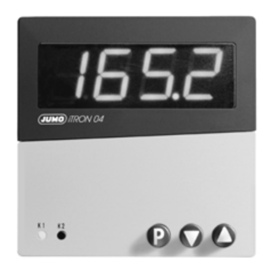
Operation Displays and keys (1) Display 7-segment display 4 places, green Display alternates when setpoints, parameters and codes are entered and indicated. Character height Type 702040/41/42: 10mm Type 702043/44: 20mm Display range -1999 to +9999 digit Decimal places none, one, two °... -
Page 13: Principle Of Operation
Principle of operation Normal display The display shows the process value. Operating level SP 1 SP 2 The setpoint is input here. On active setpoint switching via the logic input, pears in the display. When the ramp function is active, the ramp setpoint is displayed. - Page 14 Parameter level Normal display Operating level Pb:1 > 2s - setpoint 1+2 Process value Ramp setpoint* - limit value for (display only) limit comparator - controller parameters - ramp slope after last parameter after last > 2s parameter Time-out y.0 ! (30s) Configuration level C111...
-
Page 15: Operation Of The Timer Function
Operation of the timer function The timer can be operated with the keys (start, stop, cancel, acknowledge) if the timer at opera- ting level is indicated. Time-out is not active here. If the logic input is configured accordingly, then a key, such as the key, can be used. -
Page 16: Functions
Functions We recommend the following procedure: h Familiarize yourself with the controller functions h Enter the configuration codes and the parameter values in the tables provided for this pur- pose in Chapter 6. Write down the appropriate values ( ), or mark selection with a cross ). -
Page 17: Process Value Input
Process value input Symbol Notes vpage 31 C111 Transducer/probe (process value input) vpage 31 C112 Unit of process value (°C/°F)/decimal places of display vpage 35 Start/end value of value range for standard signals → Example: 0—20 mA 20—200°C: = 20 / = 200 vpage 35 OFFS... -
Page 18: Logic Input
Logic input Key inhibit Operation is possible from keys. No operation from keys. Level inhibit Access to the parameter and No access to the parameter and configuration levels is possible. configuration levels. Starting self-optimization is possible. Starting self-optimization is not possible. Ramp stop Ramp running Ramp stopped... -
Page 19: Controller
Controller Controller structure The controller structure is defined via the parameters → Example: Setting for PI controller Pb .1 =120, =0sec, =350sec Symbol Notes Controller type and assignment of the controller outputs to the physical C113 vpage 32 outputs 1+2 vpage 33 C116 Outputs in fault condition... - Page 20 Symbol Notes vpage 36 Contact spacing for double-setpoint controller vpage 36 HYS.1 Differential 1 (controller output 1) Differential 2 (controller output 2) Pb.1 Pb.2 for controllers with =0 or HYS.2 Working point (basic load) vpage 36 Output if process value=setpoint vpage 36 Output limiting - maximum output...
-
Page 21: Limit Comparator (Alarm Contact)
Limit comparator (alarm contact) lk1—lk6: Monitoring referred to the setpoint. lk7 / lk8: Monitoring referred to a fixed value w = setpoint, x = process value Symbol Notes vpage 32 C114 Limit comparator function (lk1— lk8) vpage 35 Hyst Differential of limit comparator vpage 36 Limit value of limit comparator... -
Page 22: Ramp Function
Ramp function ramp setpoint SPr process value t2 t3 power ON ( SP 1 active) t2— t3 power failure or overrange/underrange t4—t5 ramp stop setpoint switching to SP 2 Symbol Note vpage 32 C115 Ramp function (on/off, time unit) vpage 33 Ramp stop via logic input (floating contact) C117 vpage 36... -
Page 23: Self-Optimization
Self-optimization Self-optimization determines the optimum controller parameters for PID or PI controllers. Pb:1 Pb:2 Cy 1 Cy 2 The following controller parameters are defined: The controller selects procedure a or b, depending on the size of the control deviation: b) Self- Start a) Self- Start... -
Page 24: Level Inhibit Via Code
Level inhibit via code As an alternative to the logic input, the level inhibit can be set via a code (logic input has priority). h Set the code using (at least 5sec) in normal display Level inhibit via the logic input will lock the parameter and configuration levels (corresponds to code 011). -
Page 25: Timer Function (Extra Code)
Timer function (extra code) Using the timer function, the control action can be influenced by means of the adjustable time t i 0 . After the timer has been started by power ON, by pressing the key, or via the logic input, t i 0 the timer start value is counted down to 0, either instantly or after the process value has... - Page 26 Notes on the timer function in conjunction with the ramp function - Generally, the setpoints can also be approached using the ramp function. - Stopping the timer does not influence the ramp function. - If control is active after the timer has run down, the current setpoint is approached with the ramp.
- Page 27 Symbol Notes Timer function vpage 34 C120 C120=1 Time-limited control: The control is switched off after the timer has run down (output 0%) C121=3, 4, 7 or 8 C121=1, 2, 5 or 6 Diagrams with and without start above tolerance limit. ---- Tolerance limit C120=2 Time-dependent setpoint switching: After the start of the timer function, the process is con-...
- Page 28 Symbol Notes C120 Time-delayed control: The control action starts after the timer has run down. C121=1, 2, 5 or 6 C120=3 After the timer has run down ( ), the keys are used for acknowledge- ment. > 0s t i 0 C120=4 Timer: After the start of the timer function, is counted down to 0.
- Page 29 Symbol Notes vpage 34 C121 Start condition of the timer t i 0 The timer start value is counted down as selected in the following events: 1. Power ON or logic input/keys 2. Start via keys/logic input 3. Process value has reached tolerance limit (1°C or 5°C) (start via keys/logic input) The position of the tolerance limit depends on the controller type: - 1-setpoint controller (direct): tolerance limit above setpoint - 1-setpoint controller (reversed): tolerance limit below setpoint...
- Page 30 Programming example After the start via the logic input or from the keys, the process has to be controlled for 30 min- utes to a setpoint of 80°C. The control action is to be cancelled in the event of a power failure. Configuration: - C111—...
-
Page 31: Configuration And Parameter Tables
Configuration and parameter tables C112 C111 Transducer Decimal places/unit 9999/°C Pt 100 (3-wire) 999.9/°C Pt 1000 (3-wire) 99.99/°C >2s KTY11-6 (2-wire) 9999/°F Pt 100 (2-wire) 999.9/°F Pt 1000 (2-wire) 99.99/°F Cu-Con Fe-Con Cu-Con Fe-Con . . . NiCr-Ni Pt10Rh-Pt Pt13Rh-Pt Pt30Rh-Pt NiCrSi-NiSi N Pb:1... - Page 32 C113 Controller type Output 1 (relay) Output 2+3 (logic+relay) single setpoint (reversed) controller LK/timer signalling single setpoint (direct) controller LK/timer signalling double setpoint controller output 1 controller output 2 single setpoint (reversed) LK/timer signalling controller single setpoint (direct) LK/timer signalling controller double setpoint controller output 2...
- Page 33 C116 C117 Outputs on fault Logic input LK/timer no function signalling OFF 100% key inhibit -100% level inhibit LK/timer ramp stop 100% setpoint switching signalling ON timer control Minimum output limiting y.2 is effective Maximum output limiting y.1 is effective .
- Page 34 C120 Timer function no function time-limited control time-dependent setpoint switching time-delayed control timer (control independent of timer) . . . C121 Start condition for timer Action on power failure after power ON, logic input/keys Condition as before the power failure via logic input/keys via logic input/keys;...
- Page 35 C122 Timer signalling C123 Unit of time (timer) no function mm.ss (max. 99.59) timer start until run-down hh.mm (max. 99.59) after run-down for 10sec hhh.h (max. 999.9) after run-down for 1min. s = seconds; m = minutes; h = hours after run-down until acknowledgement One output has to be configured...
- Page 36 Parameter Explanation Value range factory- Your setting sP 1 setpoint 1 SPL — SPH setpoint 2 SPL — SPH sP 2 limit value of -1999 to +9999digit limit comparator Pb:1 proportional band 1 0 — 9999digit proportional band 2 0 — 9999digit Pb:2 derivative time 0 —...
-
Page 37: Alarm Messages
Alarm messages Display Description Cause/response The displays for the process Over/underrange of process value. value or timer value flashes Controller and limit comparators referred to “1999”. the process value input behave in accord- Display current timer value by ance with the configuration of the outputs. repeatedly pressing the The timer is stopped. - Page 38 Measurement circuit monitoring ( • = recognized) Transducer Overrange/ Probe/ Probe/lead break underrange lead short-circuit Thermocouple •/• • Resistance thermometer •/• • • Voltage 2 – 10V and0.2 – 1V •/• • • 0 – 10V and 0 – 1V •/- Current 4 –...
-
Page 39: Technical Data
Technical data Input for thermocouple Input for resistance thermometer Designation Designation Range Range Pt100 EN 60751 -200 to +850°C Fe-Con -200 to + 900°C Fe-Con EN 60584 -200 to +1200°C Pt1000 EN 60751 -200 to +850°C Cu-Con -200 to + 600°C KTY11-6 -50 to +150°C Cu-Con... - Page 40 200g (702044) ferrules 145g (702042) Protection Electromagnetic compatibility: EN 61 326 IP66 (front) to EN 60529 Immunity to interfer.: Class B, Interfer. emission: industrial IP20 (rear) requirements Safety regulation: to EN 61010 Approval: UL and CSA (only devices with JUMO indication)
- Page 41 JUMO GmbH & Co. KG JUMO Instrument Co. Ltd. JUMO Process Control, Inc. Street adress: JUMO House 8 Technology Boulevard Moltkestraße 13 - 31 Temple Bank, Riverway Canastota, NY 13032, USA 36039 Fulda, Germany Harlow, Essex CM20 2TT, UK Phone:...
Need help?
Do you have a question about the iTRON B 70.2040 and is the answer not in the manual?
Questions and answers