Table of Contents
Advertisement
Quick Links
Advertisement
Table of Contents

Subscribe to Our Youtube Channel
Related Manuals for Vaisala HUMICAP HMM170


Summary of Contents for Vaisala HUMICAP HMM170
- Page 1 M212259EN-A User Guide â Vaisala HUMICAP Humidity and Temperature Module HMM170...
- Page 2 English versions are This product contains software developed applicable, not the translations. by Vaisala or third parties. Use of the The contents of this document are subject software is governed by license terms and to change without prior notice.
-
Page 3: Table Of Contents
Safety........................ 12 2.9.1 ESD Protection..................12 2.10 Regulatory Compliances.................13 Installation......................14 Installing Module..................... 14 Installing Probe....................15 Vaisala Insight Software................. 16 3.3.1 Connecting to Insight Software..............16 3.3.2 Configuration Options................16 Operation......................18 Using Service Port................... 18 4.1.1 Installing the Driver for the USB Service Cable........18 Modbus...................... - Page 4 HMM170 User Guide M212259EN-A Technical Data....................29 HMM170 Specifications.................. 29 Spare Parts and Accessories................. 32 Appendix A: Modbus Reference..............33 Default Communication Settings..............33 Function Codes....................33 Data Encoding....................33 A.3.1 32-Bit Floating Point or Integer Format..........34 A.3.2 16-Bit Integer Format................34 Modbus Registers...................34 A.4.1 Measurement Data Registers..............35...
- Page 5 List of Figures List of Figures Figure 1 HMM170 Probe Head Dimensions..............10 Figure 2 HMM170 Component Board................14 Figure 3 HMM170 Probe Installation................15 Figure 4 Connecting Module to Insight............... 16 Figure 5 MI70 Indicator Parts..................20 Figure 6 MI70 Basic Display....................21 Figure 7 Recording/Viewing Menu................
- Page 6 HMM170 User Guide M212259EN-A List of Tables Table 1 Document Versions (in English)...............5 Table 2 Related Manuals....................5 Table 3 HMM170 Sensor Types..................8 Table 4 Availability of Output Parameters..............9 Table 5 Filter Types and Properties................11 Table 6 LED Indicator States...................12 Table 7 Measurement Performance................29 Table 8...
-
Page 7: About This Document
Chapter 1 – About This Document 1. About This Document 1.1 Version Information This document provides instructions for installing, operating, and maintaining Vaisala HUMICAPâ Humidity and Temperature Module HMM170. Table 1 Document Versions (in English) Document Code Date Description M212259EN-A June 2019 First version. -
Page 8: Trademarks
Indicates that you need to take some notes during the task. 1.4 Trademarks Vaisalaâ and HUMICAPâ are registered trademarks of Vaisala Oyj. All other product or company names that may be mentioned in this publication are trade names, trademarks, or registered trademarks of their respective owners. -
Page 9: Product Overview
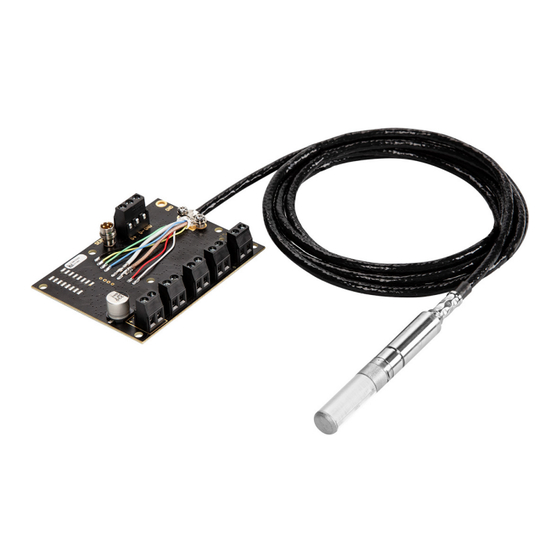
HMM170 is easy to install and convenient to use. It provides both digital and analog outputs for multiple needs. An integrated service port enables a quick and simple way to configure, check, and calibrate the module with the help of a USB cable and Vaisala Insight software. 2.2 Basic Features and Options •... -
Page 10: Sensor Types
M212259EN-A • Service port for maintenance • Supports Vaisala MI70 Handheld Measurement Indicator • Optional USB cable for easy connection to Vaisala Insight software for configuration, diagnostics, and temporary online monitoring 2.3 Sensor Types HMM170 is available with three different sensor types. -
Page 11: Output Parameters
Chapter 2 – Product Overview 2.4 Output Parameters Output parameter is available Value of output parameter is locked unless temperature is written to register 0334 from an external source Value of output parameter is locked Output parameter is not valid for sensor type Table 4 Availability of Output Parameters Output Parameter HUMICAPâ... -
Page 12: Probe Head
HMM170 User Guide M212259EN-A 2.5 Probe Head 99.5 [3.92] 79.5 [3.13] 37.5 [1.48] Groove for lock ring [in] Figure 1 HMM170 Probe Head Dimensions HMM170 is designed for applications that involve constant high humidity or rapid changes in humidity, such as drying and test chambers, combustion air, and other humidifiers and meteorological measurements, where measurement performance and chemical tolerance are essential. -
Page 13: Filter Types
Chapter 2 – Product Overview The HUMICAPâ 180L2 sensor does not support chemical purge. You can trigger a purge manually at any time with Vaisala Insight software or Modbus, or by closing the external purge trigger on the component board. -
Page 14: Safety
Green and blinking Module is powering up or communicating with the probe. Module is in error state. You can use Vaisala Insight software to disable the LED indicator. 2.9 Safety This product has been tested for safety. Note the following precautions:... -
Page 15: Regulatory Compliances
Chapter 2 – Product Overview 2.10 Regulatory Compliances HMM170 is in conformity with the provisions of the following EU directive(s): • RoHS Directive • WEEE Directive Electromagnetic compatibility of HMM170 has been tested according to the following product family standard: EN61326-1 Electrical equipment for measurement, control and laboratory use - EMC requirements - for use in light industrial environments. -
Page 16: Installation
3. Installation 3.1 Installing Module The measurement probe with cable is attached to the component board at Vaisala. Do not disconnect and reconnect the cable. 1. Attach the module securely using the mounting holes on the corners of the component board. CAUTION! The module is delivered with a set of standoffs. -
Page 17: Installing Probe
3. Let the cable hang loosely to prevent condensed water from running along the cable to the probe head. 4. Seal the cable pass-through using the Vaisala installation accessories. If the temperature of the measured environment differs greatly from ambient temperature, the whole probe and preferably plenty of cable must be inside the process. -
Page 18: Vaisala Insight Software
• Configure device features such as measurement filtering, chemical purge, heating, and serial communication Download Vaisala Insight software at www.vaisala.com/insight. HMM170 can be connected to Vaisala Insight software using a Vaisala USB cable (no. 219690). 3.3.1 Connecting to Insight Software • Computer with Vaisala Insight software installed •... - Page 19 Chapter 3 – Installation You can restore the device back to its default settings using the Factory Default Settings > Restore Settings function. Doing this will also clear any user adjustment and restore the latest factory calibration. More Information ‣ Modbus Reference (page 33)
-
Page 20: Operation
4. Operation 4.1 Using Service Port The HMM170 has a 4-pin M8 service port connector on the component board. Vaisala offers an optional USB cable (Vaisala order code 219690) for connecting the module to your PC. The service port is intended for short-term use such as calibration. For permanent installation, use the permanent digital Modbus and/or analog terminals. -
Page 21: Modbus
3. Locate the cable in the list of devices: • If the device is listed as Vaisala USB Device with a COM port number in brackets, the cable is ready for use. Note the COM port number, you will need it later. -
Page 22: Mi70 Indicator Parts
4.3.2 Connecting HMM170 to MI70 Indicator • MI70 connection cable (Vaisala order code 219980SP) 1. If the MI70 indicator is on, turn it off. 2. Connect HMM170 to port I of the MI70 indicator using the MI70 connection cable. -
Page 23: Basic Display
Chapter 4 – Operation 3. Turn on the MI70 indicator. MI70 detects the HMM170 and proceeds to show the measurement screen. After a few seconds, MI70 will start to show valid measurement results from the module. 4.3.3 Basic Display Figure 6 MI70 Basic Display Battery indicator. -
Page 24: Main Menu
HMM170 User Guide M212259EN-A 4.3.5 Main Menu In the main menu, you can configure the MI70 settings and basic display options, view information about the connected device, access recordings and clear the memory, set alarms, start adjustments, and use the analog output option of the MI70 indicator. To open the main menu and navigate in the menus: 1. -
Page 25: Recording Data
Chapter 4 – Operation 4.3.7 Recording Data With MI70, you can record measurement data over a certain period at chosen intervals. These recordings are saved in MI70 memory and are available even after MI70 is disconnected from the module. To start recording, select the Record function key in the basic display, or navigate to the recording menu: Main menu >... -
Page 26: Maintenance
HMM170 User Guide M212259EN-A 5. Maintenance 5.1 Cleaning Probe • Lint-free cloth • Isopropyl alcohol (70 %) CAUTION! Do not attempt to clean the sensors under the filter in any way. 1. Moisten a lint-free cloth with isopropyl alcohol (70%). 2. Wipe the probe head and cable with the lint-free cloth. Do not spray anything directly on the probe head or immerse the probe head in liquid, since that may deposit impurities on the sensors. -
Page 27: Calibration And Adjustment
When adjustment is necessary, you can have Vaisala calibrate and adjust the module. To order calibration services from Vaisala, visit store.vaisala.com. You can also do the adjustment yourself using the Insight software. -
Page 28: Adjustment Points And Requirements
Make sure the measurement has stabilized and the reference environment is reliable. If the required adjustment is still too large, the module needs to be serviced by Vaisala. When adjustment of humidity measurement is necessary, Vaisala recommends adjusting in two points, 11 %RH and 75 %RH. -
Page 29: Calibration And Adjustment Using Mi70
30% RH. Using the MI70 indicator, you can also do the 1-point calibration so that you compare the reading of the module to any MI70-compatible Vaisala device that provides the same measurement parameter. 1. Connect the HMM170 to port I of the MI70 indicator using the handheld connection cable. - Page 30 HMM170 User Guide M212259EN-A 5. MI70 notifies you that automatic power off is disabled during adjustment mode. Select OK to acknowledge. 6. Select RH or T parameter for adjustment and select OK. This procedure assumes you are adjusting relative humidity, but the same principles apply for temperature adjustment. 7.
-
Page 31: Technical Data
Humidity sensor types Vaisala HUMICAPâ R2C Vaisala HUMICAPâ 180L2 Vaisala HUMICAPâ 180VC Response time (90 %) at +20 °C (+68 °F) in 0.1 m/s air flow with Vaisala HUMICAPâ R2C sensor: with steel netting filter 50 s with sintered filter... -
Page 32: Figure 8 Accuracy Over Temperature Range In Temperature Measurement
HMM170 User Guide M212259EN-A °C °C -0.1 -0.2 -0.3 -0.4 -0.5 -0.6 -0.7 Figure 8 Accuracy over Temperature Range in Temperature Measurement Table 8 Operating Environment Property Description/Value Operating temperature for component board -40 ... +60 °C (-40 ... +140 °F) Operating humidity range for component board 0 ... -
Page 33: Figure 9 Probe Head Dimensions
Chapter 6 – Technical Data Property Description/Value Chemical purge at 24 VDC +220 mA Warmed probe at 24 VDC +240 mA External load < 500 Ω Start-up time 3 s at power-up Maximum wire size 0.5 ... 1.5 mm (AWG) 99.5 [3.92] 79.5 [3.13] 37.5 [1.48]... -
Page 34: Spare Parts And Accessories
HMM170 User Guide M212259EN-A 6.2 Spare Parts and Accessories Table 10 Spare Parts and Accessories Item Order Code USB cable for PC connection 219690 MI70 connection cable 219980SP Feedthrough HMP247CG Swagelok NPT 1/2" adapter SWG12NPT12 Swagelok ISO 1/2" adapter SWG12ISO12 Duct installation kit for probe 210697 PPS Plastic grid and stainless steel netting DRW010281SP... -
Page 35: Appendix A: Modbus Reference
Appendix A – Modbus Reference Appendix A. Modbus Reference A.1 Default Communication Settings Table 11 Default Modbus Serial Communication Settings Property Description/Value Serial bit rate 19200 Parity None Number of data bits Number of stop bits Flow control None Modbus device address You can use up to ten probes on the same RS-485 line. You must configure each probe on the line to have a different Modbus address. -
Page 36: 32-Bit Floating Point Or Integer Format
HMM170 User Guide M212259EN-A A.3.1 32-Bit Floating Point or Integer Format Least significant 16 bits of floating point or integer numbers are placed at the smaller Modbus address as specified in Open Modbus TCP Specification, Release 1.0. This is also known as "little-endian"... -
Page 37: Measurement Data Registers
Appendix A – Modbus Reference Accessing unavailable (temporarily missing) measurement data does not generate an exception. “Unavailable” value (a quiet NaN for floating point data or 8000 for integer data) is returned instead. An exception is generated only for any access outside the applicable register ranges. - Page 38 HMM170 User Guide M212259EN-A Register Address Register Description Data Format Metric Unit Number (Hexadecimal) (Decimal) Floating Point Values 0028 Relative saturation 32-bit float 0040 Water mass fraction 32-bit float Integer Values 0100 Relative humidity 16-bit signed %RH * 100 integer 0101 Temperature 16-bit signed...
-
Page 39: Configuration Registers
Appendix A – Modbus Reference Integer Values 0110 Absolute humidity at 16-bit signed * 100 integer 0111 Parts per million in oil 16-bit signed integer 0114 Relative saturation 16-bit signed % * 100 integer 0120 Water mass fraction 16-bit signed integer A.4.2 Configuration Registers Table 15 Modbus Configuration Data Registers (Writable) - Page 40 HMM170 User Guide M212259EN-A Compensation Setpoints 0300 Pressure compensation 32-bit float Unit: hPA setpoint Default: 1013.25 0334 Temperature 32-bit float Unit: °C compensation setpoint. If a value is written to this register, the device uses it instead of its own temperature measurement.
- Page 41 Appendix A – Modbus Reference Filtering 031A Measurement filtering 32-bit float Range: 0.000 ... factor 1.000 1.000 = Reading shows 100 % of the most recent measured value (no filtering, default). 0.01 ... 0.99 = Reading shows 1 ... 99 % of the most recent measured value and part of the...
- Page 42 HMM170 User Guide M212259EN-A Communication 1538 0601 Bit rate enum 0 = 300 1 = 600 2 = 1200 3 = 2400 4 = 4800 5 = 9600 6 = 19200 7 = 38400 8 = 57600 9 = 115200 1539 0602 Parity, data, stop bits...
-
Page 43: Device Identification Objects
Example Contents (Decimal) VendorName “Vaisala” ProductCode "HMM170" VendorUrl “http://www.vaisala.com/” ProductName "Vaisala HUMICAP(R) Humidity and Temperature Module HMM170" SerialNumber "NOT SET" CalibrationDate CalibrationText A.4.4 Test Value Registers Read the known test values from the test registers to verify the functionality of your Modbus implementation. -
Page 44: Modbus Communication Examples
HMM170 User Guide M212259EN-A A.4.5 Modbus Communication Examples Reading Relative Humidity Value Device address used in the following examples is 240 (F0 The values returned by the device differ depending on the ambient conditions and/or device settings. Your device might not return exactly the same values. Request Response Bytes on the Line... - Page 45 Appendix A – Modbus Reference Writing Pressure Compensation Value Request Response Bytes on the Line Description Bytes on the Line Description (Hexadecimal) (Hexadecimal) (silence for 3.5 bytes) Start of Modbus RTU (silence for 3.5 bytes) Start of Modbus RTU frame frame Device address Device address...
- Page 46 HMM170 User Guide M212259EN-A Communication Description Data format Two 16-bit Modbus registers interpreted as IEEE 754 binary32 floating point value, least significant word first. Value to write 44756E14 = 981.72 (hPa)
-
Page 47: Warranty
Please see the applicable supply contract or Conditions of Sale for details of the warranty for each product. Technical Support Contact Vaisala technical support at helpdesk@vaisala.com. Provide at least the following supporting information: • Product name, model, and serial number •... - Page 48 HMM170 User Guide M212259EN-A...
- Page 50 www. v aisala.com...
Need help?
Do you have a question about the HUMICAP HMM170 and is the answer not in the manual?
Questions and answers