Table of Contents
Advertisement
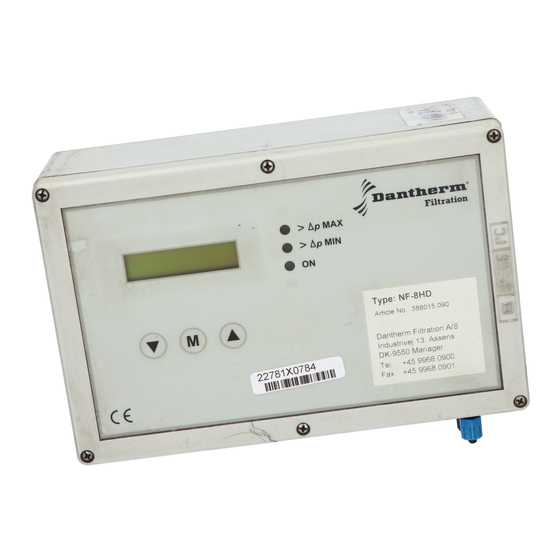
NF-8HD / NF-16HD CONTROLLER
CONTENTS:
Safety Instructions
Installation Manual
Operating Instructions
Maintenance Instructions
Spare parts
MANUAL FOR
(AUG 2005 Vers. 1005)
Tab. 05.51 Page 06.01-06.02
Tab. 05.91 Page 05.01-05.12
Tab. 05.91 Page 07.01-07.04
Tab. 05.91 Page 08.01
Tab. 05.91 Page 09.01
Advertisement
Table of Contents

Related Manuals for Dantherm NF-8HD


Summary of Contents for Dantherm NF-8HD
- Page 1 MANUAL FOR NF-8HD / NF-16HD CONTROLLER (AUG 2005 Vers. 1005) CONTENTS: Safety Instructions Tab. 05.51 Page 06.01-06.02 Installation Manual Tab. 05.91 Page 05.01-05.12 Operating Instructions Tab. 05.91 Page 07.01-07.04 Maintenance Instructions Tab. 05.91 Page 08.01 Spare parts Tab. 05.91 Page 09.01...
- Page 2 01SEP05 1004GB Cat. 20 / Tab. 05.51 / Page 06.01 SAFETY REGULATIONS NF10 Disregarding Dantherm Filtration safety regulations entails a heavy safety risk. Maintenance. Maintenance must be performed to Dantherm Filtration maintenance directions. Open fire, sparking or other form of heat generation such as: Welding, grinding, boring/drilling or smoking etc.
- Page 3 01SEP05 1004GB Cat. 20 / Tab. 05.51 / Page 06.02 Respiratory Protective Device, possibly with fresh air supply. Goggles, possibly shield mask in connection with fresh air supply. For fire/explosive dust, the following must also be used: Fire Retardant Suit. Fire Retardant Working Gloves.
- Page 4 The control system is entirely assembled and tested. Connection. The filter control system NF-8HD is mounted right in front of the first 8 valves. If more than 8 valves are present, an NF-8E expansion unit is mounted immediately in front of the next 8 valves or a NF-16HD can be used.
- Page 5 E1(10) and E2 (11) or select DTC Mode 3. Application of the down-time- cleaning functions is a condition on all Dantherm Filtration guarantees. The set of con- tacts is potentialfree and is activated most appropriately by an auxiliary relay in the fan con- trol system: •...
- Page 6 01AUG 1005GB Cat.20 / Tab. 05.91 / Page 05.03 To save the new values, press the M button for more than 3 seconds. The controller automati- cally returns from the parameter setting mode to the parameter-selecting mode when the val- ues are saved.
- Page 7 01AUG 1005GB Cat.20 / Tab. 05.91 / Page 05.04 State of Operation The state of operation is indicated by the 3 light emitting diodes (LEDs) (Fig. 4, 1.1, 1.2, and 1.3) and the filter differential pressure is indicated in plain text. LED 1.1 (ON): is illuminated if the unit is operational.
- Page 8 01AUG 1005GB Cat.20 / Tab. 05.91 / Page 05.05 DTC Down-Time Cleaning The DTC is activated differently dependent of the selected method. DTC Mode 1: Fig. 1: In DTC Mode 1 the down-time cleaning procedure is started on the terminals E1 and E2 (Fan stops: E1-E2 open) DTC Mode 2: Fig.
- Page 9 01AUG 1005GB Cat.20 / Tab. 05.91 / Page 05.06 DTC Mode 3: Delta-P DTCmax Fig. 3: In DTC Mode 3 the down-time cleaning procedure is started when the pressure comes under the ∆p- DTCmin limit, but only if the ∆p-DTCmax has been exceeded. The terminals E1 and E2 are not taken into account.
- Page 10 01AUG 1005GB Cat.20 / Tab. 05.91 / Page 05.07 Final inspection after installation. • Check that the circuit voltage is 230V AC 50-60 Hz. • Monitoring of valve and unit function by starting the test operation. • The down-time-cleaning procedure is tested by briefly opening and closing the terminals E1 and E2 (first select DTC mode 1) •...
- Page 11 Data link to expansion units B1, B2, B3, B4 Data link to programming output signal (only NF-16HD) Data link to Delta P external display 4-20 mA (only NF-8HD 4-20mA and NF-16HD) Fig. 5:Terminals in the filter controller NF-8HD / NF-16HD...
- Page 12 . . . Ventile 2 bis 8 24V DC Data input terminals from main unit Terminals for connection of 1 – 8 solenoid valves Data output terminals for the following expansion units Fig. 6: Terminals for the expansion unit NF-8E NF-8HD NF-8E NF-8E (NF-16HD) (NF-16E) (NF-16E)
- Page 13 230 V ON / OFF 50-60 Hz p extern ON / OFF Nur bei DTC-Modi 1 oder 2 Fig. 8: Connection of compressed air hoses for NF-8HD NF-16HD 250 V AC 0,4 A 9 10 11 12 13 34 35...
- Page 14 To return to the operating mode Press the ∇-button and the ∆-button for more than 3 seconds to return to the operating mode. Parameter list; NF-8HD standard values in the ( ). • ∆p -MIN (700 Pa) • ∆p -MAX (1300 Pa) •...
- Page 15 01AUG 1005GB Cat.20 / Tab. 05.91 / Page 05.012 >3 s ∆p ∆p >3 s >1 s 10 s >1 s Fig. 10: Short description of how to check and change the parameters.
- Page 16 Replace the fuse. • • The plant’s emergency stop is Check the emergency stop. activated • • Internal control error Contact Dantherm Filtration service • • No valve activation Defect lead connection Check cables and cable connec- tions • •...
- Page 17 Data link to expansion units B1, B2, B3, B4 Data link to programming output signal (only NF-16HD) Data link to Delta P external display 4-20 mA (only NF-8HD 4-20mA and NF-16HD) Fig. 2:Terminals in the filter controller NF-8HD / NF-16HD...
- Page 18 01AUG 1005GB Cat.20 / Tab. 05.91 / Page 08.01 MAINTENANCE INSTRUCTIONS for the filter control unit NF-8HD / NF-16HD Safety precautions Adjustment of electrical controllers with the casing removed may only be carried out by spe- cialised personnel and in full accordance with the stipulated safety rules.
- Page 19 01AUG 1005GB Cat.20 / Tab. 05.91 / Page 09.01 LIST OF SPARE PARTS for the filter control NF-8HD / NF-16HD Whenever there is an error in the control system itself, then either the set of fuses or the whole constrol unit has to be replaced.
Need help?
Do you have a question about the NF-8HD and is the answer not in the manual?
Questions and answers