Table of Contents
Advertisement
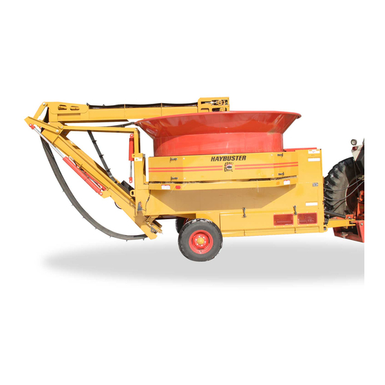
Operating Instructions and Parts Reference
H-1000
PTO Driven Tub Grinder
Serial Number FI03631 & Up
0500044 • M
2014
ay
TM
P
roduct
D
T
I
I
ura
ech
nDusTrIes
nTernaTIonal
Po B
1940, J
ox
amesTown
T
: (701) 252-4601• F
el
ax
.
.
www
DuraTechInDusTrIes
neT
I
nformatIon
I
.
nc
, nD 58402-1940
: (701) 252-0502
•
.
.
www
hayBusTer
com
Advertisement
Table of Contents
Troubleshooting

Related Manuals for Haybuster H-1000

Summary of Contents for Haybuster H-1000
- Page 1 Operating Instructions and Parts Reference H-1000 PTO Driven Tub Grinder Serial Number FI03631 & Up roduct nformatIon nDusTrIes nTernaTIonal Po B 1940, J , nD 58402-1940 amesTown : (701) 252-4601• F : (701) 252-0502 • 0500044 • M 2014 DuraTechInDusTrIes...
- Page 2 A Tradition of Innovation Since 1966...
- Page 3 H-1000 Tub Grinder as of the date of publication. DuraTech Industries reserves the right to make updates to the machine from time to time. Even in the event of such updates, you should still find this manual to be appropriate for the safe operation and maintenance of your unit.
- Page 4 A Tradition of Innovation Since 1966...
- Page 5 • Section 3.1, “Pre-Operation Inspection”. Appropriate use of unit The H-1000 Tub Grinder is designed to grind material into more palatable or man- ageable rations for your operation. It has multiple uses: Grind most types of hay • Big round bales • Loose hay...
- Page 6 WARNING: The OPERATOR IS RESPONSIBLE for the safety of the operator and those in the surrounding area. Operators and those observing the operation of the H-1000 Tub Grinder are required to wear head, eye, and ear protection, No loose clothing is allowed.
-
Page 7: Table Of Contents
Assembly Required ................... 19 Section 3: Operation ..............21 Pre-Operating Inspection ................21 Introduction to the machine ..............23 3.2.1 Description of the H-1000 Tub Grinder ........23 3.2.2 Overview of Operator’s Controls..........23 3.2.3 Electronic governor ..............24 3.2.4 Rotor ................... 24 3.2.5 Screens .................. - Page 8 Lubrication ....................44 Hydraulic system ..................49 Hammermill maintenance ................. 50 Hammer maintenance and replacement ............ 51 Section 5: Troubleshooting the H-1000 Tub Grinder ....53 Troubleshooting the electronic governor system ........53 General Troubleshooting ................57 Appendix A: Warranty ............... 58 Appendix B: H-1000 Tub Grinder Specifications ......
- Page 9 DECALS ......................126 DECAL LOCATIONS ..................128 H-1000 TUB GRINDER DOCUMENTATION COMMENT FORM .. 131 H - 1 0 0 0 T U B G R I N D E R O P E R A T I N G I N S T R U C T I O N S...
- Page 10 A Tradition of Innovation Since 1966 H - 1 0 0 0 T U B G R I N D E R O P E R A T I N G I N S T R U C T I O N S...
-
Page 11: Part 1: Operating Instructions
H-1000 PTO Driven Tub Grinder Serial Number FI03631 & Up Part 1: Operating Instructions H - 1 0 0 0 T U B G R I N D E R O P E R A T I N G I N S T R U C T I O N S... -
Page 12: Introduction
The purpose of this owner’s manual is to explain maintenance requirements and routine adjustments for the most efficient operation of your H-1000 Tub Grinder. There is also a trouble shooting section that may help in case of problems in the field. Any information not covered in this manual may be obtained from your dealer. - Page 13 Appendix A provides details of the warranty. Operator responsibilities • Review Section 2, ”Dealer Preparation,” to verify that the H-1000 Tub Grinder has been prepared for use. • Note the important safety information in the Foreword and in Section 1, “Safety.”...
-
Page 14: Section 1: Safety
THIS MACHINE IS NOT TO BE USED FOR ANY PURPOSE OTHER THAN THOSE EXPLAINED IN THE OPERATOR’S MANUAL, ADVERTISING LITERATURE OR OTHER DURATECH WRITTEN MATERIAL PERTAINING TO THE H-1000 TUB GRINDER. 1.1 Safety-alert symbols Decals are illustrated in Part 2: Parts Reference. - Page 15 DANGER: Indicates an imminently hazardous situation that, if not avoided, will result in death or serious injury. This signal word is to be limited to the most extreme situations, typically for machine components that, for functional purposes, cannot be guarded. WARNING: Indicates a potentially hazardous situation that, if not avoided, could result in death or serious injury, and includes hazards...
-
Page 16: Operator - Personal Equipment
Do not operate a H-1000 when you are fatigued. Be alert - If you get tired while operating your H-1000, take a break. Fatigue may result in loss of control. Working with any farm equipment can be strenuous. If you have any condition... -
Page 17: Machine Safety Labels
Machine safety labels The safety decals located on your machine contain important information that will help you operate your equipment. Become familiar with the decals and their locations. DANGER: ROTATING PARTS WITHIN CAN KILL OR DISMEMBER. WAIT FOR ALL MOVEMENT TO STOP BEFORE SERVICING, UNLOADING, OR INSPECTING MACHINE. - Page 18 WARNING: FOR YOUR PROTECTION AND PROTECTION OF OTHERS, PRACTICE THE FOLLOWING SAFETY RULES. BEFORE OPERATING THIS MACHINE, READ THE OPERATOR’S MANUALS SUPPLIED WITH THIS MACHINE AND YOUR TRACTOR. CHECK OPERATORS MANUALS TO BE SURE 6500041 YOUR TRACTOR MEETS THE MINIMUM REQUIREMENTS FOR THIS MACHINE.
- Page 19 WARNING: OVERHEAD CONVEYOR HAZARD TO PREVENT SERIOUS INJURY OR DEATH: DO NOT WALK UNDER CONVEYOR AT ANY TIME. 6500214 STAY CLEAR OF CONVEYOR DURING OPERATION, RAISING, AND LOWERING. LOWER CONVEYOR FULLY BEFORE SERVICING. KEEP OTHERS AWAY. WARNING: OVERHEAD CONVEYOR HAZARD TO PREVENT SERIOUS INJURY OR DEATH: DO NOT WALK UNDER CONVEYOR AT ANY TIME.
- Page 20 CAUTION: KEEP WHEEL BOLTS TIGHT. 6500042 CAUTION: ADJUST TRACTOR DRAWBAR SO THAT THE DISTANCE FROM THE END OF THE P.T.O. SHAFT ON THE TRACTOR TO THE CENTER OF THE DRAWBAR HITCH PIN IS 16”. 6500057 CAUTION: INSERT TRANSPORT LOCKS BEFORE MOVING ON ROADS.
-
Page 21: Thrown Objects And Operator Safety
Figure 1.2. Figure 1.1 VIEWED FROM THE REAR OF THE H-1000 NOTE: The difference in the size of the area for side A versus side B. Side B is larger. Dimensioning the size of this area is not practical. The distance a thrown object may travel is dependent on several conditions, including, but not limited to, rotor speed and diameter, condition of the hammers, style of hammers, object mass, object shape, amount of material in the tub, and how the hammer strikes the object. -
Page 22: Shielding
Shielding This H-1000 Tub Grinder is equipped with shielding at all major points of potential injury. All Shields should be kept in place during operation. Bodily injury may occur if the unit is operated without shields. WARNING: Shields are installed for your protection and to keep material off machine parts. Do not operate this PTO Driven Tub Grinder without shields in place. -
Page 23: Safety Review
Use a tractor that meets the requirements contained in this manual. See Appendix C, Required for Operation, page 60. Make sure the H-1000 Tub Grinder is in good operating condition and that all protective shields are in place and in proper working order. Replace damaged shields before operating. - Page 24 Because it is possible that your H-1000 may be used in dry areas or the presence of combustibles, special precautions should be taken to prevent fires and fire fighting equipment should be readily available.
-
Page 25: Fire Prevention
Wait for all movement to stop. Disconnect PTO driveline from tractor. CAUTION: At full speed, energy is stored in the rotor. Do not use the tractor PTO brake to stop the rotor. Reduce engine speed before disengaging the PTO Fire Prevention Grinding wood, hay, and other products in a tub grinder produces a large amount of potentially combustible material. -
Page 26: Fire Extinguishers
REMOVAL AND CLEANING INSTRUCTIONS: • Clean the engine compartment daily or more often if conditions require it be done more frequently. When cleaning the engine compartment, always clean the top of the engine and the areas around exhaust manifolds, exhaust plumbing and turbochargers. •... -
Page 27: Towing
Be sure all loose parts are securely fastened down. Make sure all bystanders are clear. Hitch H-1000 Tub Grinder to a tow vehicle with adequate load carrying and braking capacity. Be sure to attach safety chains between tow vehicle and H-1000 Tub Grinder. Tongue weight is 900 lbs. -
Page 28: Service And Maintenance
THIS MACHINE IS NOT TO BE USED FOR ANY PURPOSE OTHER THAN THOSE EXPLAINED IN THE OPERATOR’S MANUAL, ADVERTISING LITERATURE OR OTHER DURATECH WRITTEN MATERIAL PERTAINING TO THE H-1000 TUB GRINDER. H - 1 0 0 0 T U B G R I N D E R... -
Page 29: Section 2: Dealer Preparation
Before starting to assemble conveyor to H-1000 Tub Grinder frame, park H-1000 Tub Grinder on level ground and place conveyor behind H-1000 Tub Grinder. Review shipping kit list and verify that all small parts are in the shipping kit. Review Part Book pages on the Hydraulic Conveyor Lift to identify arrangement of parts listed below. - Page 30 STEP 6: Verify the type of tractor to be used with the H-1000 Tub Grinder. John Deere series 60 and older tractors require the closed center plug option ( see page 90, hydraulic valve 4000128), all other tractors use the open center plug.
-
Page 31: Section 3: Operation
There is no substitute for a sound preventative maintenance program and a well-trained operator. To insure long life and economical operation, learn how to operate the H-1000 Tub Grinder and how to use the controls properly. Thoroughly instruct the operator in maintenance and operation of the H-1000 Tub. - Page 32 Check screens and screen hold downs for wear and tightness. Check installation and condition of hammers. Visually examine rotor bearings and mounting bolts. Check all bearings for wear. Check chains and belts for proper tension and condition. Make sure all shields and guards are in place. Condition of decals.
-
Page 33: Introduction To The Machine
Introduction to the machine 3.2.1 Description of the H-1000 Tub Grinder The Tub Grinder is designed to grind most types of hay, grain and crop residue such as stover and straw. The unit incorporates a number of basic features including the rotating tub, the electronic governor, the rotor and hammer assemblies, the tub chain and drive assemblies, belly and discharge conveyors, and the axle and hitch assemblies. -
Page 34: Electronic Governor
Rotor The Rotor and screens are the heart of the tub grinder. The rotor on this H-1000 Tub Grinder is equipped with 64 swinging hammers. Dull edges on the hammers and/or screens will result in a loss of capacity and increased horse power requirements. -
Page 35: Screens
Screens All H-1000 Tub Grinders require two screens. They come equipped from the factory with a 3” diameter hole screen and a 4” diameter hole screen. Any combination of hole sizes may be used. As a general rule, use the largest diameter screens capable of doing the job. -
Page 36: Slug Buster And Mill Grate
3.2.7 Slug Buster and Mill Grate A slug buster or mill grate is installed above the rotor to regulate the amount of material entering the rotor chamber. The standard slug buster is used for ideal grinding conditions (dry hay). The mill grate is used for “less than ideal grinding”, (wet hay or tough grasses). -
Page 37: Machine Operation
Machine Operation 3.3.1 Tractor Set Up A tractor drawbar and 3-point arms can cause interference with the PTO driveline. This interference can cause serious damage to the PTO guarding and the PTO telescoping members. If this implement is attached to a tractor with a clevis hitch (hammer strap) style drawbar, the hammer-strap must be removed to prevent damage to the PTO guarding and the PTO telescoping members. -
Page 38: How To Hook Up To Tractor
To reduce wear on the PTO shaft knuckle joints, tractor PTO shaft should be in line (parallel) with the H-1000 Tub Grinder. If tractor is equipped with swinging drawbar, adjust so the tractor PTO and H-1000 Tub Grinder drive shaft are in line. - Page 39 GRINDING Place materials to be ground directly into the tub. The best method for filling the H-1000 Tub Grinder is: Engage rotor and increase engine speed to 1000 RPM on the P.T.O. shaft. Fill the tub about half full of unground materials before starting tub rotation.
-
Page 40: Shutdown Procedures
Before working on or near the H-1000 Tub Grinder for any reason, including servicing, inspecting or unclogging machine: Run H-1000 Tub Grinder until discharge conveyor is empty, and grind as much of the material in the tub as possible. Reduce engine speed to idle. -
Page 41: Emergency Shutdown Procedure
3.4.2 Emergency Shutdown Procedure Disengage PTO and tractor hydraulics Storage 3.5.1 Preparing for storage To prepare the unit for storage, perform the following steps: Check the wheel bearings for lubrication requirements and adjustments at the end of the season. Check the pressure roller bearings for lubrication and adjustments at the end of the season. Clean the machine thoroughly to prevent rust and to make inspections easier. - Page 42 Figure 3.4 steps to folding the conveyor procedure Step 2 latch in fold position Step 1 Step 4 Step 3 conveyor strap conveyor lock pin Step 5 Step 6 transport locking pin H - 1 0 0 0 T U B G R I N D E R O P E R A T I N G I N S T R U C T I O N S...
-
Page 43: Road Transport
3.7.2 Set up to transport Inspect H-1000 Tub Grinder for any loose parts, tools, or any materials. Remove them or fasten them securely to the H-1000 Tub Grinder. To set up the H-1000 Tub Grinder for transport, perform the following steps: Fold the conveyor. -
Page 44: Parts Of The Electronic Governor
Parts of the electronic governor FUSE LIGHT This light is on whenever the electronic governor is receiving power. SENSOR LIGHT This light is on whenever the electronic governor is receiving an adequate input signal from the sensor and the rotor is engaged. -
Page 45: Operation Of The Electronic Governor
Figure 3.5 speed lights fuse light electronic governor controls sensor light range switch engine load knob tub speed knob tub mode switch NOTE: some units may be labeled automatic and manual Operation of the electronic governor Engine (Auto) mode IMPORTANT: Except when calibrating or trouble shooting the electronic governor always use the engine (Auto) mode of the electronic governor. -
Page 46: Calibration Of The Electronic Governor
To calibrate the electronic governor, perform the following steps: Begin calibration procedure with H-1000 Tub Grinder completely shutdown. Place the MODE switch in the OFF position and the RANGE switch in the H-High position. Rotate the TUB LIMIT KNOB fully clockwise toward the rabbit position. -
Page 47: Adjusting The Conveyor Belt Tension
3.12 Adjusting the conveyor belt tension The discharge conveyor is adjustable to allow for belt stretch and tracking. If the conveyor belt slows down or stops during operation, slippage may be the cause. To eliminate slippage, tighten the adjusting bolts on the conveyor equally. This will increase the conveyor belt’s tension and help to keep the belt centered on the rollers. -
Page 48: Adjusting The Conveyor Belt Tracking
3.13 Adjusting the conveyor belt tracking When a new belt is installed: Use only genuine DuraTech Industries parts. Begin by adjusting the drive roller so that the mounting bearings are the same distance from the end of the conveyor frame. This ensures that the roller centerline is square with conveyor frame. Adjust the idler roller bolts so that they are equal on both sides of the conveyor. -
Page 49: Main Drive Belt Adjustment
3.14 Main drive belt adjustment Adjustment has been provided for tightening main drive belts. Belts tend to stretch rapidly when first put into operation. Tighten regularly to prevent slippage. Belt tension should be checked at 30-minute intervals or as necessary until stretch is eliminated. -
Page 50: Electro-Hydraulic Valve Calibration
MANUAL OVERRIDE NOTE: If there is an electrical failure with the machine, it may still be able to grind. Switch the electronic governor off. Remove the rubber end cap and loosen the jam nut on the electro-hydraulic valve. Start the machine and engage the tub drive. CAUTION: PTO MUST BE ENGAGED AT THIS TIME. -
Page 51: Sensor Test
If tub is not turning, you are ready to proceed to the grinding section of this book. Remember the engine load knob adjusts the load placed on the engine, and under normal conditions this will be the only adjustment you will have to make. IMPORTANT: Stay clear of all moving parts while calibrating the electro-hydraulic valve. -
Page 52: Section 4: General Maintenance
Before working on or near the H-1000 Tub Grinder for any reason, including servicing, inspecting or unclogging machine: Run H-1000 Tub Grinder until discharge conveyor is empty, and grind as much of the material in the tub as possible. Reduce engine speed to idle. - Page 53 Check for loose or worn chains, belts, sprockets and pulleys. Keep sprockets and pulleys aligned. Inspect rotor and all rotating parts for wrapped twine or wire build up. If machine is going to sit idle for an extended period of time, tub floor should be cleaned to prevent rust and sticking problems at start up time.
-
Page 54: Lubrication
Hydraulic oil reservoir capacity: 12 gallons. Change hydraulic oil and filter at least once a year. Gear Box: Check level periodically. Drain and refill with No. 90 gear lube once a year. When operating the H-1000 Tub Grinder during cold weather, perform all lubrication after bearings are at operating temperatures. - Page 55 Lubrication Chart H - 1 0 0 0 T U B G R I N D E R O P E R A T I N G I N S T R U C T I O N S...
- Page 56 Figure 4.1 4 zerks above operator controls tub drive shaft bearing (Ref # 1) tub chain idler (Ref # 4) rotor bearing (Ref # 8) tub chain idler pivot (Ref # 5) Figure 4.2 2 zerks on opposite side of machine from operator controls hydraulic motor pivot (Ref # 6) tub drive shaft bearing (Ref # 1)
- Page 57 Figure 4.4 discharge conveyor bearings both discharge conveyor (Ref # 11) support pivots, discharge conveyor spring fold and two discharge conveyor bearings discharge conveyor spring fold (Ref # 14) discharge conveyor support pivot (Ref # 13) Figure 4.5 second rotor bearing lubrication point rotor bearing (Ref # 8) Figure 4.6...
- Page 58 Figure 4.7 two of three PTO lubrication points PTO extension PTO lubrication point (Ref #12) PTO lubrication point (Ref #12) Figure 4.8 belly pan auger drive bearing lubrication points belly pan auger drive bearings (Ref # 9) H - 1 0 0 0 T U B G R I N D E R O P E R A T I N G I N S T R U C T I O N S...
-
Page 59: Hydraulic System
Hydraulic system CAUTION: Lack of proper oil level in the reservoir tank will cause system to heat under continuous running. Check the hydraulic oil level daily and replace as necessary. All machines have been pre-run at the factory to insure all functions are performing correctly. -
Page 60: Hammermill Maintenance
Hammermill maintenance Visually examine the mill to see if any of the internal parts show excessive wear. These parts should include rotor discs and the holes in the discs that support the rods. Enlarged holes can cause rods to break or bend. Also check rods, rod locking or retaining devices, hammers, screens, screen tracks and hold downs, main shaft, platform locking devices, hinges or anything else that could wear and perhaps fail and causing damage to the hammermill and/or personnel safety if not properly maintained. -
Page 61: Hammer Maintenance And Replacement
Hammer maintenance and replacement CAUTION: Follow normal shutdown procedure before entering tub to do any service work. When installing or changing hammers, be sure to follow hammer pattern diagram carefully (page 52). Misplacement could cause excessive vibration. We recommend the following: Always replace hammers in pairs, 180 degrees apart. - Page 62 Figure 4.11 hammer spacing chart for the H-1000 H - 1 0 0 0 T U B G R I N D E R O P E R A T I N G I N S T R U C T I O N S...
-
Page 63: Section 5: Troubleshooting The H-1000 Tub Grinder
Section 5: Troubleshooting the H-1000 Tub Grinder 5.1 Troubleshooting the electronic governor system When power is reaching the electronic governor the fuse light should be on. If this light fails to go on, check the fuse, the battery connections, the wiring harness, and the indicator lamp. - Page 64 Checking the ENGINE MODE operation of the electronic governor. If the tub mode controls function correctly after following the tub mode trouble shooting check list, then follow the calibration instructions on page 36 of this manual. If the tub will not rotate, proceed to trouble shooting table below. H - 1 0 0 0 T U B G R I N D E R O P E R A T I N G I N S T R U C T I O N S...
- Page 65 ELECTRONIC GOVERNOR HARDWARE TEST Power source: 12 volts DC Red wire + positive pin A wiring harness Black wire - Negative Pin B wiring harness Test output voltage to valve DC Red wire + positive pin D wiring harness. Black wire - negative pin E. wiring harness. Test the electronic governor with power supplied to the governor control box and the mode switch set to the tub position.
- Page 66 Output voltage of sensor AC red wire - Pin C wiring harness Black wire - Pin B wiring harness. Set the sensor gap to 3/32”. Remove the wiring harness from the electronic governor. With the grinder at operating speed. Set volt meter to AC volts, connect leads to pins B and C. The volt meter should read at least 2 to 3 volts AC.
-
Page 67: General Troubleshooting
General Troubleshooting H - 1 0 0 0 T U B G R I N D E R O P E R A T I N G I N S T R U C T I O N S... -
Page 68: Appendix A: Warranty
Appendix A: Warranty DuraTech Industries International Inc. (DuraTech Industries) warrants to its authorized dealer, who in turn warrants to the original purchaser for twelve (12) months from Retail Sale Date that this product will be free from defects in material and workmanship when used as intended and under normal maintenance and operating conditions. This warranty shall become void if in the judgment of DuraTech Industries International, Inc. -
Page 69: Appendix B: H-1000 Tub Grinder Specifications
Feed Delivery ....20 ft. folding rubber belt conveyor w/cleats 18 in. Wide Tub size ..................96 in. (244 cm) I.D. Tub Depth ..................44 1/2 in. (113 cm) Tub Drive ..................Electro-Hydraulic Options AVAILABLE OPTIONS FOR HAYBUSTER H-1000 Tub Grinder: • Ear Corn Kit • Geyser Plate •... -
Page 70: Appendix C: Required For Operation
Appendix C: Required for operation Tractor - 80 to 175 hp 1000 RPM PT0 Shaft Dual Hydraulics, double acting control valve, 8 GPM, 1500 psi See also Section 3.3.1, Tractor Set Up, and section 3.2.9 Open and closed center valves Grinder Approximately 6 gallons of hydraulic oil. -
Page 71: Part 2: Parts Reference
H-1000 PTO Driven Tub Grinder Serial Number FI03631 & Up Part 2: Parts Reference... -
Page 72: Bull Wheel Frame Assembly
B U L L W H E E L F R A M E A S S E M B L Y H - 1 0 0 0 T U B G R I N D E R P A R T S R E F E R E N C E... - Page 73 B U L L W H E E L F R A M E A S S E M B L Y ITEM PART QTY. PART DESCRIPTION 1400008 5.0-2 Cast Pulley 1400069 SHVE\B8\20.0 for SN 3807 and up 1400017 SHVE\B8\18.4 1400504 P1-1 3/4”...
-
Page 74: Main Frame Assembly S.n. Up To Gi3756
M A I N F R A M E A S S E M B L Y S . N . U P T O G I 3 7 5 6 H - 1 0 0 0 T U B G R I N D E R P A R T S R E F E R E N C E... - Page 75 M A I N F R A M E A S S E M B L Y S . N . U P T O G I 3 7 5 6 ITEM PART QTY. PART DESCRIPTION 4500556 Guard\PTO\Front 4500557 Frame\Grdr\H100095 4500558 Door\Drive\Side\LH 4500753...
-
Page 76: Main Frame Assembly S.n. Gi3757 And Up
M A I N F R A M E A S S E M B L Y S . N . G I 3 7 5 7 A N D U P H - 1 0 0 0 T U B G R I N D E R P A R T S R E F E R E N C E... - Page 77 M A I N F R A M E A S S E M B L Y S . N . G I 3 7 5 7 A N D U P ITEM PART QTY. PART DESCRIPTION 4500556 Guard\PTO\Front 4500557 Frame\Grdr\H100095 4500558 Door\Drive\Side\LH...
-
Page 78: Platform Assembly
P L A T F O R M A S S E M B L Y H - 1 0 0 0 T U B G R I N D E R P A R T S R E F E R E N C E... - Page 79 P L A T F O R M A S S E M B L Y ITEM PART QTY. PART DESCRIPTION 1200013 #2 Tub Roller 1200005 #44 Roller Stand Thru S/N 4001 4501313 Rllr\Press\Stnd S/N 4002 and up-See Pressure Roller page 1200008 #5 Pressure Roller Thru S/N 4001 4500088...
-
Page 80: Pressure Roller Assembly S.n. Gi4002 & Up
P R E S S U R E R O L L E R A S S E M B L Y S . N . G I 4 0 0 2 & U P H - 1 0 0 0 T U B G R I N D E R P A R T S R E F E R E N C E... - Page 81 P R E S S U R E R O L L E R A S S E M B L Y S . N . G I 4 0 0 2 & U P ITEM PART QTY. PART DESCRIPTION 4501317 PRESSURE ROLLER COMPLETE 4501313...
-
Page 82: Tub Drive Assembly
T U B D R I V E A S S E M B L Y H - 1 0 0 0 T U B G R I N D E R P A R T S R E F E R E N C E... - Page 83 T U B D R I V E A S S E M B L Y ITEM PART QTY. PART DESCRIPTION 4500566 DR\TUB\ASSY\H1000 1000033 Spkt\60\30\1-1/4\1/4 1000077 Spkt\80\30\1-1/4\1/4 1000134 Spkt\60\12\1-1/4\5/16 1100062 #60 Connector Link 1100063 #60 Offset Link 1100088 60-43-Cl Chain 1100094 2080 Chain 157 Links +OF/CL 1100070...
-
Page 84: Tub Assembly (S.n. Up To 4441)
T U B A S S E M B L Y ( S . N . U P T O 4 4 4 1 ) H - 1 0 0 0 T U B G R I N D E R P A R T S R E F E R E N C E... - Page 85 T U B A S S E M B L Y ( S . N . U P T O 4 4 4 1 ) ITEM PART QTY. PART DESCRIPTION 4500568 TUB\ASSY\H1000W/CHAIN&AGTTRS 4500724 Agttr\Tub\10 for Ser. No. FI3631 to FI3656 4500756 Agttr\Tub\10 for Ser.
-
Page 86: Tub Assembly (S.n. 4541 And Up)
T U B A S S E M B L Y ( S . N . 4 5 4 1 A N D U P ) H - 1 0 0 0 T U B G R I N D E R P A R T S R E F E R E N C E... - Page 87 T U B A S S E M B L Y ( S . N . 4 5 4 1 A N D U P ) ITEM PART QTY. PART DESCRIPTION 4502397 4502409 AGTTR\TUB\FIN\10 4502410 AGTTR\TUB\FIN\14 4800106 BOLT\HEX\5/8X1-1/2 4900005 NUT\HEX\5/8\NC 5000003 WASH\LOCK\5/8 H - 1 0 0 0 T U B G R I N D E R...
-
Page 88: Rotor Assembly
R O T O R A S S E M B L Y H - 1 0 0 0 T U B G R I N D E R P A R T S R E F E R E N C E... - Page 89 R O T O R A S S E M B L Y ITEM PART QTY. PART DESCRIPTION 1400016 Pulley\Cast\11-8B 1400519 Hub\R2-2-3/4 2000508 Brg\PillowBlock\2-7/16 2000509 Brg\PillowBlock\2-3/4 4500248 Spacer\Hammer\1-1/2X1.028X1 4501316 Spacer\Hammer\1-1/2X1.028X1/2 4500444 Shim\Brg\10Ga\3x10⁻¹/4 4500445 Shim\Brg\10Ga\3x11-1/4 4500019 Plate\Rotor\15-3/4x.1875T 4500020 Plate\Rotor\3/16 4500021 Plate\Rotor\1/2 4700267 Nut\Rotor\3 w/o Shoulder 4500023...
-
Page 90: Conveyor Drive Assembly S.n. Up To Gi3756
C O N V E Y O R D R I V E A S S E M B L Y S . N . U P T O G I 3 7 5 6 H - 1 0 0 0 T U B G R I N D E R P A R T S R E F E R E N C E... - Page 91 C O N V E Y O R D R I V E A S S E M B L Y S . N . U P T O G I 3 7 5 6 ITEM PART QTY. PART DESCRIPTION 1000042 Spkt\50\15\1\1/4\Sub 1000128...
-
Page 92: Conveyor Drive Assembly S.n. Gi3757 And Up
C O N V E Y O R D R I V E A S S E M B L Y S . N . G I 3 7 5 7 A N D U P H - 1 0 0 0 T U B G R I N D E R P A R T S R E F E R E N C E... - Page 93 C O N V E Y O R D R I V E A S S E M B L Y S . N . G I 3 7 5 7 A N D U P ITEM PART QTY. PART DESCRIPTION 4500585 DR\CNVYR\ASSY\SUB 1000042...
-
Page 94: Belly Conveyor Assembly
B E L L Y C O N V E Y O R A S S E M B L Y H - 1 0 0 0 T U B G R I N D E R P A R T S R E F E R E N C E... - Page 95 B E L L Y C O N V E Y O R A S S E M B L Y ITEM PART QTY. PART DESCRIPTION 1000038 Spkt\50\17\5/8\Idler 1000121 Spkt\50\30\1-1/4\1/4\Grip 2000016 Wood Block Idler 2000314 4 - 1-1/4 Cast Flng Brg 4500003 Auger\RH\9x96 4500046...
-
Page 96: Lower Discharge Conveyor Assembly
L O W E R D I S C H A R G E C O N V E Y O R A S S E M B L Y H - 1 0 0 0 T U B G R I N D E R P A R T S R E F E R E N C E... - Page 97 L O W E R D I S C H A R G E C O N V E Y O R A S S E M B L Y ITEM PART QTY. PART DESCRIPTION 1000092 Spkt\60\20\1\1/4\Soft 1400082 Cable Sheave w\Bearings for Ser. No. up to GI3756 1700017 18x39-4Full Cleats CVB 2000507...
-
Page 98: Upper Discharge Conveyor Assembly
U P P E R D I S C H A R G E C O N V E Y O R A S S E M B L Y H - 1 0 0 0 T U B G R I N D E R P A R T S R E F E R E N C E... - Page 99 U P P E R D I S C H A R G E C O N V E Y O R A S S E M B L Y ITEM PART QTY. PART DESCRIPTION 2000507 Brg\PillowBlock\1-1/8 4500942 Rllr\Idler\Cnvyr\Dschrg\6x18 4500196 Arm\Cnvyr\Spring 4500201 Tube\Cnvyr\3/4x1/2x3/4...
-
Page 100: Hydraulic Assembly
H Y D R A U L I C A S S E M B L Y H - 1 0 0 0 T U B G R I N D E R P A R T S R E F E R E N C E... - Page 101 H Y D R A U L I C A S S E M B L Y ITEM PART QTY. PART DESCRIPTION 3700091 Hose\Hyd\1/2x22\SW-SO 3700110 Hose\Hyd\1/2x20\SW-SO 3700230 Hose\Hyd\1/2x32\SW\Oring 3700236 Hose\Hyd\1x31 3700328 Hose\Hyd\1/2x28\SW-SO 3700329 Hose\Hyd\1/2x29\SW-Oring 3800008 1/2 90Deg Street Elbow 3800010 3/4x1/2 Bushing 3800015 Nipple\3/4x2...
-
Page 102: Hydraulic Electric Solenoid Valve
H Y D R A U L I C E L E C T R I C S O L E N O I D V A L V E H - 1 0 0 0 T U B G R I N D E R P A R T S R E F E R E N C E... - Page 103 H Y D R A U L I C E L E C T R I C S O L E N O I D V A L V E PART QTY. PART DESCRIPTION CV93 4300030 HYD. ELECTRIC SOLENOID VALVE 12V 20GPM CV98 4300065 VALVE\SERVO\15GPM\12VDC...
-
Page 104: Hydraulic Valve - 4000128
H Y D R A U L I C V A L V E - 4 0 0 0 1 2 8 MODEL BA - one spool ITEM PART PART DESCRIPTION 4000001 HANDLE/HYD/VALVE BANK 4000002 CONNECTOR LINK W/PIN 4000004 BRKT/HYD/VALVE BANK 4000006 VALVE\ADJ\RELIEF 4000029... - Page 105 H Y D R A U L I C V A L V E - 4 0 0 0 0 9 5 ITEM PART QTY. PART DESCRIPTION 4000006 New Adj. Relief Valve 4000001 Valve Handle 4000002 Connector Links Handle 4000003 Pin Handle w/Key 4000004 Handle Bracket...
-
Page 106: Tub Drive Motor Assembly
T U B D R I V E M O T O R A S S E M B L Y ITEM PART NO. QTY. PART DESCRIPTION 6200004 5/16 X 1-1/2 Key 3900011 Flange Mount 3900005 Complete Orbit Motor-2000 Series 14.9 C.I. 7501005 Seal Kit Complete 2000 Series 3900010... -
Page 107: Assembly
P . T . O . A S S E M B L Y ITEM PART QTY. PART DESCRIPTION 3600101 l-55 Univ. Joint & TelescopingShaftAssembly Comp. w/1-3/8 21-Spline Yoke 3600141 PTO Complete L55 w/1-3/4 20Spline (not shown) 3600017 Joint & Shaft Half w/Guard, Tractor 1/2 Complete w/1-3/8 21-Spline Yoke 3600100 Joint &... -
Page 108: Assembly With Plastic Guards
P . T . O . A S S E M B L Y W I T H P L A S T I C G U A R D S ITEM PART QTY. PART DESCRIPTION 3600474 PTO\COMP\55R\1-3/8-21CLRX1-3/4CLAMP;W/3/8KW 3600469 PTO\COMP\55R\1-3/4-20QDX1-3/4CLAMP;W/3/8KW\PLASTC 3600013 CROSS &... - Page 109 A Tradition of Innovation Since 1966 H - 1 0 0 0 T U B G R I N D E R P A R T S R E F E R E N C E...
-
Page 110: Hydraulic Conveyor Lift Assembly S.n. Up To Gi3756
H Y D R A U L I C C O N V E Y O R L I F T A S S E M B L Y S . N . U P T O G I 3 7 5 6 H - 1 0 0 0 T U B G R I N D E R P A R T S R E F E R E N C E... - Page 111 H Y D R A U L I C C O N V E Y O R L I F T A S S E M B L Y S . N . U P T O G I 3 7 5 6 ITEM PART QTY.
-
Page 112: Hydraulic Conveyor Lift Assembly S.n. Gi3757 To Gi3806
H Y D R A U L I C C O N V E Y O R L I F T A S S E M B L Y S . N . G I 3 7 5 7 T O G I 3 8 0 6 H - 1 0 0 0 T U B G R I N D E R P A R T S R E F E R E N C E... - Page 113 H Y D R A U L I C C O N V E Y O R L I F T A S S E M B L Y S . N . G I 3 7 5 7 T O G I 3 8 0 6 PART QTY.
-
Page 114: Hydraulic Conveyor Lift Assembly S.n. Gi3807 And Up
H Y D R A U L I C C O N V E Y O R L I F T A S S E M B L Y S . N . G I 3 8 0 7 A N D U P H - 1 0 0 0 T U B G R I N D E R P A R T S R E F E R E N C E... - Page 115 H Y D R A U L I C C O N V E Y O R L I F T A S S E M B L Y S . N . G I 3 8 0 7 A N D U P PART QTY.
-
Page 116: Hydraulic Cylinder
H Y D R A U L I C C Y L I N D E R H - 1 0 0 0 T U B G R I N D E R P A R T S R E F E R E N C E... - Page 117 H Y D R A U L I C C Y L I N D E R ITEM PART QTY. PART DESCRIPTION 4100103 Cyl\Hyd\Kit\Seal\3\1-1/2” Rod 4100132 Cyl\Hyd\Yoke 4100174 Cyl\Hyd\Rod\1-1/2\3x36 4100102 Cyl\Hyd\Gland\1-1/2” Rod 4100104 Cyl\Hyd\Piston\3” 4100111 Cyl\Hyd\3x36 FOR CONVEYOR LIFT (FOR SN. GI3757 AND UP) 4100251 KIT\SEAL\CYL\HYD\3-1/2”...
-
Page 118: Electronic Governor Assembly S.n. Up To Gi3756
E L E C T R O N I C G O V E R N O R A S S E M B L Y S . N . U P T O G I 3 7 5 6 ITEM PART NO. - Page 119 E L E C T R O N I C G O V E R N O R A S S E M B L Y S . N . G I 3 7 5 7 A N D U P ITEM PART QTY.
-
Page 120: Wheel Assembly
W H E E L A S S E M B L Y H - 1 0 0 0 T U B G R I N D E R P A R T S R E F E R E N C E... - Page 121 W H E E L A S S E M B L Y ITEM PART QTY. PART DESCRIPTION 2600013 9.5X14-8Ply Tire 2600406 9.5x14-15 Tube 2600601 14x8 Wheel 1&3 2600825 Whl\Assy\9.5x14x8ply\Imp\Tire&Wheel 2900069 Hub\Wheel Hub(631)Complete 3000005 5/32x1-1/2 Cotter Key 2900013 Hub Cap\Wheel Hub(DC-13) 4900054 Nut\Spindle\7/8-14\NF 5000055...
-
Page 122: Gear Box Assembly
G E A R B O X A S S E M B L Y H - 1 0 0 0 T U B G R I N D E R P A R T S R E F E R E N C E... - Page 123 G E A R B O X A S S E M B L Y ITEM PART QTY. PART DESCRIPTION 3100322 Open Center Case 3100323 Quill 1.98 Dia. Seal 3100324 Open Cover 3100325 Closed Cover 3100326 19T Gear 2900032 Cone 2900033 3100327 Snap Ring...
-
Page 124: Rear Hay Guide Assembly (Option)
R E A R H A Y G U I D E A S S E M B L Y ( O P T I O N ) H - 1 0 0 0 T U B G R I N D E R P A R T S R E F E R E N C E... - Page 125 R E A R H A Y G U I D E A S S E M B L Y ( O P T I O N ) ITEM PART QTY. PART DESCRIPTION 4500670 Option Hay Guide Complete 4500920 Bracket \Hay Guide 4500671 Pipe\Hay Guide\36”...
-
Page 126: Front Hay Guide Assembly (Option)
F R O N T H A Y G U I D E A S S E M B L Y ( O P T I O N ) H - 1 0 0 0 T U B G R I N D E R P A R T S R E F E R E N C E... - Page 127 F R O N T H A Y G U I D E A S S E M B L Y ( O P T I O N ) PART QTY. PART DESCRIPTION 4501439 GUIDE\HAY\KIT\H1000\2000 4501220 FRM\GUIDE\HAY\H1000&H1100 4501435 BRKT\GUIDE\HAY\LH\H1000 4501436 BRKT\GUIDE\HAY\RH\H1000 4800068 BOLT\HEX\1/2X3...
-
Page 128: Mill Grate (Option)
M I L L G R A T E ( O P T I O N ) H - 1 0 0 0 T U B G R I N D E R P A R T S R E F E R E N C E... - Page 129 M I L L G R A T E ( O P T I O N ) ITEM PART QTY. PART DESCRIPTION 4500667 Grate\Mill 5000002 Wash\Flat\5/8 5000003 Wash\Lock\5/8 4800010 Bolt\Hex\5/8x2 4500726 Grate\Mill\Kit 4501282 Plate\Geyser\Slotted\H1000 - For use with the mill grate H - 1 0 0 0 T U B G R I N D E R P A R T S R E F E R E N C E...
-
Page 130: Geyser Plate (Option)
G E Y S E R P L A T E ( O P T I O N ) H - 1 0 0 0 T U B G R I N D E R P A R T S R E F E R E N C E... - Page 131 G E Y S E R P L A T E ( O P T I O N ) ITEM PART QTY. PART DESCRIPTION 4500673 Pl\Geyser\H1000\Kit 4500672 Plate\Geyser\H1000 5000002 Wash\Flat\5/8 5000003 Wash\Lock\5/8 4800010 Bolt\Hex\5/8x2 4501282 Plate\Geyser\Slotted\H1000 - For use with the mill grate H - 1 0 0 0 T U B G R I N D E R P A R T S R E F E R E N C E...
-
Page 132: Grain Grinding Hopper (Option)
G R A I N G R I N D I N G H O P P E R ( O P T I O N ) H - 1 0 0 0 T U B G R I N D E R P A R T S R E F E R E N C E... - Page 133 G R A I N G R I N D I N G H O P P E R ( O P T I O N ) ITEM PART QTY. PART DESCRIPTION 4501349 HPPR\GRAIN\\ASSY\COMPLETE 4501335 HPPR\GRAIN 4501339 CVR\RTR\HPPR\GRAIN 4501341 CVR\END\HPPR\GRAIN 4800003 BOLT\HEX\3/8X1 4800034...
-
Page 134: Ear Corn Kit (Option)
E A R C O R N K I T ( O P T I O N ) H - 1 0 0 0 T U B G R I N D E R P A R T S R E F E R E N C E... - Page 135 E A R C O R N K I T ( O P T I O N ) ITEM PART QTY. PART DESCRIPTION 4500752 Optn\Ear Corn\H-100095 4500750 Cover\Rotor\Ear Corn 4500751 Brkt\Cover\Rotor\Ear Corn 4500122 Cross Pipes 4800114 Bolt\Hex\1/2x2 5000004 Wash\Flat\1/2 4900001 Nut\Hex\1/2\NC 4800010 Bolt\Hex\5/8x2...
-
Page 136: Decals
D E C A L S H-1000 H - 1 0 0 0 T U B G R I N D E R P A R T S R E F E R E N C E... - Page 137 D E C A L S ITEM PART QTY. PART DESCRIPTION 6500002 Decal\Kit\H-1000 5700192 Lamp\Reflector\Amber\4-3/8x1-7/8\Self Stick 5700193 Lamp\Reflector\Red\4-3/8x1-7/8\Self Stick 6500020 Decal\Logo\Hybstr\Sunburst 6500040 Decal\Warn\Shield;Protection 6500041 Decal\Warn\Protection 6500042 Decal\Warn\Keep;Wheel;Bolts;Tight 6500043 Decal\Warn\No;Riders 6500044 Decal\Logo\Big Bite 6500052 Decal\Info\Oil;Level 6500054 Decal\Logo\H-1000 6500056 Decal\Info\Rotation\Str 6500057 Decal\Caution\Adj.Draw;Bar 6500082 Decal\Warn\Rotating Parts Within 6500085 Decal\Danger\Rotating;Driveline...
-
Page 138: Decal Locations
D E C A L L O C A T I O N S H - 1 0 0 0 T U B G R I N D E R P A R T S R E F E R E N C E... - Page 139 D E C A L L O C A T I O N S H - 1 0 0 0 T U B G R I N D E R P A R T S R E F E R E N C E...
- Page 140 A Tradition of Innovation Since 1966 H - 1 0 0 0 T U B G R I N D E R P A R T S R E F E R E N C E...
-
Page 141: H-1000 Tub Grinder Documentation Comment Form
H-1000 Tub Grinder Documentation Comment Form DuraTech Industries welcomes your comments and suggestions regarding the quality and usefulness of this manual. Your comments help us improve the documentation to better meet your needs. • Did you find any errors? • Is the information clearly presented? • Does the manual give you all the information you need to operate the equipment safely and effectively? • Are the diagrams and illustrations correct? - Page 142 A Tradition of Innovation Since 1966 H - 1 0 0 0 T U B G R I N D E R P A R T S R E F E R E N C E...
Need help?
Do you have a question about the H-1000 and is the answer not in the manual?
Questions and answers