Table of Contents
Advertisement
Quick Links
Advertisement
Table of Contents

Related Manuals for Briot Silver


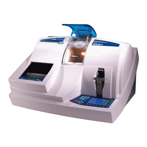
Summary of Contents for Briot Silver
- Page 2 Dear Valued Customer, You have acquired a Silver edger. We would like to thank you for the confidence you have shown in our brand. This edger has been manufactured with the greatest care. Before using it in the best possible conditions, we advise you to read this manual carefully and to keep it near your workstation, where you will be able to refer to it easily.
-
Page 4: Table Of Contents
List of accessories and consumables _____________________________________44 Accessories ______________________________________________________________ 44 Consumables ____________________________________________________________ 46 Settings and adjustments ______________________________________________47 Adjusting the screen contrast ________________________________________________ 47 Selecting a language _______________________________________________________ 48 Checking if the temperature compensation is activated/deactivated___________________ 48 Adjusting the size corrections ________________________________________________ 49 Silver FC 00 511... - Page 5 Call up a job saved on the server ___________________________________________________ C-5 Job uploading function disabled ______________________________________________________ 6 Annex D Use of the barcode reader Connection to the edger ___________________________________________________ D-3 Use ___________________________________________________________________ D-4 Annex E Technical Specifications Technical characteristics ___________________________________________________ E-3 Silver FC 00 511...
-
Page 6: On-Site Repair
On-site Repair... -
Page 8: Technician Visits
On-site Repair Technician visits At each client visit, the Briot technician is asked to write in the following table. Date of visit Name of the N° of the repair order technician Silver FC 00 511... -
Page 10: Installation / Starting
Installation / Starting... -
Page 12: General View
Installation / Starting General view LLUSTRATION The following picture gives you a general view of your edger. Edging unit Scanform™ Lay-out/blocking unit Installation / Starting... -
Page 13: Unpacking Machine
Installation / Starting Unpacking Machine ARNING If you proceed to install your edger yourself, please do not discard boxes or any of its packing contents. ROCEDURE Follow the steps below to unpack your edger unit. Step Action Illustration Remove the edger cover guard, by using the ¼-turn key contained in accessory box. - Page 14 Installation / Starting Remove the wedge from the top of the lifting jack. Loosen and remove the nut and the two washers of the threaded rod coming from the left of lifting jack. Remove the lifting jack wedge and its rod inserted in the translation tube.
-
Page 16: Safety Precautions
600w x 510h x 460d mm to place the water container. • The pump Briot supplies pump systems especially made for the required water supply to Accura and for filtering of the edging waste, with the following dimensions. Width: 600 mm (24”) - Page 17 Plug the drain pipe to the chassis of the machine. Connect the water intake hose(s) to the machine and to the faucet or the pump. Note: In case of installation on direct water only, add a filter joint contained in the accessory box. Silver FC 00 511...
- Page 18 Adjust the water flow by starting a cycle without lens. Adjust each watering using the supply adjustment wheels cf. paragraph Adjustments below. Close the cover and make one or two jobs to check the well functioning of the machine. Silver FC 00 511...
- Page 19 (2) It must not be too plentiful to avoid the formation of a mist that could moisten the TP rough edging wheel and create an undesirable “ribbon” edging of the polycarbonate. Installation on Workbench Silver FC 00 511...
-
Page 22: Introduction To The Machine
Tighten/loosen the lens clamp. Note: This key exists also to the left of the edging station, for left-handed people. Maintenance function. Refer to Annex A, paragraph Emptying the main tank. Correct error while in entry process. Silver FC 00 511... - Page 23 Unmarked key (Fct0 to Fct5), its meaning depends of the parameter displayed to the left of this key. Unmarked key (Fct6 to Fct9), its meaning depends of the parameter displayed facing this key. Initial Display When turned on, the edger initializes automatically and displays the following screen. Silver FC 00 511...
-
Page 24: Scanform Unit
Use : Introduction to your machine ™ CANFORM UNIT Description The Scanform™ integrated on the left of the machine is composed of the following units: • frame positioning station; • jaw-opening plate. Illustration Frame positioning station Jaw-opening plate Silver FC 00 511... -
Page 25: Basic Concepts
Basic concepts ASIC ONCEPTS Three Working Modes The edger makes three basic operations corresponding to a screen called "mode" that you can identify by a symbol located on right side of the screen. Mode Screen Functions Tracing Allow you to enter the following parameters: •... - Page 26 Basic concepts Going from One Mode to the Other To switch from one mode to the other, press on the function key Fct 1 and display the desired screen. The screens scroll in the following order: 1. Tracing screen: 2. Lay-out screen: 3.
-
Page 28: Precautions For Use
Never manipulate the lens feeler pliers located in the edging station. THE MANUFACTURER CANNOT BE HELD RESPONSIBLE FOR ANY DAMAGE CAUSED BY THE USE OF THE EDGER IF THE SAFETY REGULATIONS AND THE PRECAUTIONS FOR USE ARE NOT OBSERVED. Silver FC 00 511... -
Page 29: Standard Use
Functions : illustration Fct 0 Fct 1 Fct 2 Fct 3 Fct 4 Fct 5 Functions : description The following table describes each function with regard to the tracing screen of the Silver. Function Selection Description Fct0 Tracing Mode Fct1 Metallic frame... -
Page 30: Tracing A Frame Shape
Result: the frame is held. Make sure that the joints of the eye wires to be traced are properly closed. Silver FC 00 511... -
Page 31: Tracing A Pattern Or A Demonstration Lens Shape
Support Pattern gabarit holder right side 1. Select 2. Insert the pattern placing the nose part to the left or insert the left-hand demonstration lens. Support Pattern gabarit holder Silver FC 00 511... - Page 32 Result: the tracing is stopped and the following message is displayed: Press the function key Fct8. Result: the message disappears from the screen. Note: you can resume the tracing again. To do this, see the previous procedure. Silver FC 00 511...
-
Page 33: Laying Out And Blocking A Lens
Fct 1 Fct 2 Fct 3 Fct 4 Fct 5 Fct 6 Fct 7 Functions: description The following table describes each function of the Silver lay-out/blocking screen. Function Selection Description Fct0 Lay-out/Blocking Mode Fct1 Lay-out/Blocking of the right side Lay-out/Blocking of the left side... -
Page 34: Laying Out And Blocking The Lens
• • Enter the client’s binocular pupil distance using Fct3. Result: the machine automatically interprets the entered value as being: +62.00 • a total pupillary distance +30.00 • a monocular pupillary distance +06.00 • a decentration Silver FC 00 511... - Page 35 Operate the blocker arm by pushing on the two tabs designed for this. Caution! Hold the blocker arm as it returns to make sure it does not hit the body of the machine. Silver FC 00 511...
- Page 36 Visually inspect the lens shape on the screen, under the lens blank to verify the lens blank is large enough. • Compare the lens blank side diameter to the diameter value displayed at the top of the screen. Example: Ø45 Lens Layout/Blocking Illustration Single Vision Bifocal Progressive Silver FC 00 511...
-
Page 37: Edging A Lens
Fct 3 Fct 4 Fct 5 Fct 7 Fct 8 Fct 9 Functions : description The following table describes each function with regard to the edging screen of the Silver. Function Selection Description Fct0 Edging Mode Fct1 Edging the right side... -
Page 38: Edging A Lens
To clamp the lens you have to hold the key until the clamping shaft is in contact with the lens. • If you release this key during closing of the lens clamp shaft, the clamping system opens automatically. Silver FC 00 511... - Page 39 Check the following edging parameters and re-select them if needed • type of lens (Fct 2); • type of finishing (Fct 3) ; • type of sub-finishing (Fct 4); • type of counter-weight (Fct 7 and 8); • polishing option (Fct 9). Silver FC 00 511...
-
Page 40: Re-Feeling A Lens
Result: If these three operations are not sufficient, the lens is much too small, the machine cannot edge it. Perform the finishing cycle. To do this, go to step 7 – phase 3 of the procedure Edging a lens above. Silver FC 00 511... -
Page 41: Beveling A Lens
Allow the lens index to be moved to the left. Make it possible to select the bevel point the position of which will be changed (the opposite point is the pivot which cannot move). Allow the lens to be re-felt. Silver FC 00 511... - Page 42 Hold the lens whilst pressing the key of the keypad to open the lens clamp. Remove the lens from the edger without unblocking it so as to be able to retouch it after checking the size and if necessary. Silver FC 00 511...
-
Page 43: Retouching A Lens
When the reworking cycle is finished, open the visor manually. Hold the edged lens whilst pressing the key of the keypad (or the one located on the left of the edging station for left-handers) to open the lens clamp. Silver FC 00 511... -
Page 44: Operational Limits
¾ Organic Roughing: 50000 lenses ¾ Finishing: 8000 lenses ¾ Polishing: 10000 lenses • Maximal radius of the lens so that it can be felt : r ≤ 43 EMORY • Memory capacity: 156 jobs (117 +39) Silver FC 00 511... -
Page 46: Maintenance
Maintenance... -
Page 48: User Maintenance
• to replace the lens feeler tip when it is bent. • to change the water in the tank regularly if your machine operates in a closed circuit. Silver FC 00 511... -
Page 49: List Of Accessories And Consumables
Lens to lens offset adjustment tool 14 04 192 Lens feeler tip replacement tool 14 04 283 Lens to lens and pattern holder 11 90 517 Display window protector 11 22 154 Lens holder ring 02 20 150 Silver FC 00 511... - Page 50 PACKING Oregon pipe Ø 30 mm (standard version) 21 92 024 Oregon pipe Ø 50 mm (polycarbonate version) 21 92 066 Oregon pipe Ø 100 mm (polycarbonate version) 21 13 002 Protective cover 11 40 139 Silver FC 00 511...
-
Page 51: Consumables
01 14 007 Swivel lens clamping socket washer - Ø 19mm 11 38 161 Swivel lens clamping socket - Ø 25mm 11 38 162 Frame-clip tube large model 11 92 093 Frame-clip tube small model 11 92 074 Silver FC 00 511... -
Page 52: Settings And Adjustments
: to darken the screen contrast • : to lighten the screen contrast. Polarizing View Finder To adjust the brightness of the recorded shape with the screen, rotate the polarizing eyepiece in either direction to suit you best. Silver FC 00 511... -
Page 53: Selecting A Language
( • When the temperature compensation is activated, the expansion of the edging wheels due to the water temperature is automatically corrected. • The temperature compensation is activated by default. To deactivate it, contact your retailer. Silver FC 00 511... -
Page 54: Adjusting The Size Corrections
Enter the desired value with the keypad. For overall the value by default is equal to... correction 0 mm If the frame is in... the value by default is equal to... Metal 0 mm Plastic 0.30mm Silver FC 00 511... -
Page 55: Emptying The Internal Memory
Press twice on the key Result: the following screen is displayed. Fct3 Press the function key Fct3. Result: all the jobs have been deleted. Press the key to confirm the deletion and/or move to the following adjustment. Silver FC 00 511... -
Page 56: Dressing The Wheels
Fct 3 Select the wheel to be dressed with the function keys: • Fct1 : glass roughing wheel • Fct2 : finishing wheel • Fct3 : polishing wheel Result: The following screen is displayed (with Fct1): Silver FC 00 511... - Page 57 Once dressing is finished, open the visor manually. Then remove the disc from the edger. Result: The following screen is displayed: the screen shown step 2 is displayed. Select another If you select wheel to dress. Silver FC 00 511...
-
Page 58: Adjusting The Lens Sizes (Reset Sizes)
Here, glass finish Here, mineral. To edge, press OK. Insert a mineral lens with a diameter • to 40 mm. Press the key. Result: the lens is edged on the rimless part of the finishing wheel. Silver FC 00 511... - Page 59 It is possible to stop the tracing. To do so, press Fct 6. Result : the screen with regard to the size adjustment of the selected lens type is displayed . Then process the tracing again. Silver FC 00 511...
- Page 60 Plastic, ∅ > 50 mm 3. Bevel Finishing Mineral, ∅ > 40 mm 4. Glass polishing Plastic, ∅ > 40 mm When the sizes are adjusted, the following screen is displayed: Select and save your adjustments. Silver FC 00 511...
-
Page 62: Changing The Lens Feeler Tip
Put in a new lens feeler tip. Caution! Do not press the lens feeler arm. Move the lens feeler arm to the left using function Fct3. Remove the lens feeler tip replacement tool. Select to confirm the change of lens feeler tip. Silver FC 00 511... -
Page 63: Adjusting The Scanform
Note : It is impossible to interrupt an adjustment in progress. When the movement of the adjustment in progress stops, select Result: You leave the adjustment in progress and return to the first Scanform™ adjustment screen. Enter or confirm the values again. Silver FC 00 511... - Page 64 The tracer measures the positions r and R as well as h1 and h2. Note : if you interrupt the adjustment, start it again from step 1 of the present procedure. Silver FC 00 511...
- Page 65 Then, the screen shown opposite is displayed. When the adjustment is finished, remove tool n° 14 04 185. Place the round pattern n° 14 04 192 (Ø40 mm) on the pattern holder. Insert the pattern holder on the frame holder. Silver FC 00 511...
- Page 66 14 04 191. Consult the screen shown at step 14. The presence of an exclamation mark displayed between the measurement name and the measurement value indicates an adjustment beyond the tolerance levels. Silver FC 00 511...
- Page 67 Result: the screen shown opposite is displayed. Select Result: the screen shown opposite is displayed. Select Result: the screen shown opposite is displayed. Select to save the adjustment of the Scanform™. Result: the screen shown opposite is displayed. Silver FC 00 511...
- Page 68 Maintenance: Settings and adjustments Step Action Illustration Select to leave the adjustment dialogue. Result: the machine re-initializes and then the tracing screen is displayed. Silver FC 00 511...
-
Page 69: Adjusting The Lens Feeling
Result: the screen shown opposite is displayed. Put adjustment tool n° 14 04 199 on the lens adapter shaft (left side). Press the key to close the lens clamp. Select Result: the tracing adjustment performs automatically. Silver FC 00 511... -
Page 70: Consulting The Statistics
Lens counters Procedure To consult the lens counters, proceed as follows. Step Action When you are in tracing mode, press simultaneously the keys. Result: the screen with regard to the counting of lenses roughed down is displayed. Silver FC 00 511... - Page 71 Result: the screen with regard to the counting of lenses with a glass finish is displayed. Press the key. Result: the screen with regard to the counting of lenses with a bevel finish is displayed. Silver FC 00 511...
- Page 72 Result: the screen with regard to the counting of lenses retouched with a glass finish is displayed. Press the key. Result: the screen with regard to the counting of lenses retouched with a bevel finish is displayed. Silver FC 00 511...
-
Page 73: Wheel Dressing
Number of mineral roughing wheel dressings performed. Number of finishing wheel dressings performed. Number of polishing wheel dressings performed. Press the key. Result: the statistics screen with regard to the lens feeler adjustment is displayed (refer to the following paragraph, step 1). Silver FC 00 511... -
Page 74: Lens Feeler, Lens Size And Scanform™ Adjustments
Number of lens feeler adjustments performed. Number of size adjustments performed. Number of Scanform™ adjustments performed. Press the key. Result: the statistics screen with regard to the type of tracing is displayed (refer to the following paragraph, step 1). Silver FC 00 511... -
Page 75: Type Of Tracing
Parameter Number of frames traced in full, i.e. left side + right side. Number of frames partially traced, i.e. one side only. Number of patterns traced. Press the key to go back to the tracing screen. Silver FC 00 511... -
Page 76: Messages
By selecting Yes or No. Question Indicate that you must choose between two solutions. • While the message is displayed, the operator dialogue is inhibited. • The message area disappears from the screen when the message is acknowledged. Silver FC 00 511... -
Page 77: List
Are you sure? If yes, the current job is deleted 03 11 Incompatible edger config. Incompatibility problem between job parameters and edger setting. Example: job with Polycarbonate lenses on a machine not equipped with TP wheel. Silver FC 00 511... -
Page 78: Origin: Edging
Origin: Extension card The following list shows the messages linked to the extension card. Type Message Cause 06 02 Job not found The frame recalled does not exist on the server. Silver FC 00 511... -
Page 80: Annexes
Annexes... -
Page 82: Annex A Operation In Recirculating Mode
Annex A Operation in recirculating mode... -
Page 84: Installing The Recirculating System
Electrical connection (front view) Raccordement électrique Do not mount the joint filter on the water supply in the case of Water supply Adduction a recirculating system. d’eau Evacuation d’eau Water outlet Filtre Pump filter Decantation/filter Décantation/filtre pompe Silver FC 00 511... -
Page 85: Cleaning The Pump
• Fill the tank up to 6 to 7 mm (2-3 inches) from the top of the main tank. • Make an void cycle (no lens) to prime the pump and edger. A - 4 Silver FC 00 511... -
Page 86: Emptying Main Tank
When the emptying is finished, press the Fct1 key and display Result: the pump stops. Turn off the dump pipe faucet. Re-connect the water supply pipe to the edger. Press the key to reboot the machine. Silver FC 00 511... -
Page 88: Annex B Use Of The Internal Memory
Annex B Use of the internal memory... -
Page 90: Introduction
(39, 38,37, etc.). When the last 39 jobs are saved, it totally deletes block n°1, i.e. the first 39 jobs. The last block replaces the first. Silver FC 00 511... -
Page 91: Using The Internal Memory
Refer to the section Creating a job. Access the lay-out/blocking screen and enter the job data (distance, height etc.). Refer to the section Lay-out. Access the edging screen and enter the job data (lens type, bevel, etc.) Refer to the section Edging. Silver FC 00 511... -
Page 92: Advice
Move to the lay-out/blocking and edging screens in order to block and edge the lens. Refer to the sections Lay-out and Edging. If you selected the save option , repeat steps 8 and 9 of the procedure Creating and Saving a Job as before. Silver FC 00 511... - Page 93 Annex B - Use of the internal memory Note To call a job, you can also use the barcode reader. Proceed as follows: • Read the job barcodes using the mini-scanner. Result: The shape you have called appears. Silver FC 00 511...
-
Page 94: Annex C Connection To The Oma Network
Annex C Connection to the OMA network... -
Page 96: Introduction
Fct7 Fct8 The current job will not be saved on the server. The current job will be saved on the server. Caution ! The job is saved once you call or create another one. Silver FC 00 511 C- 3... -
Page 97: Connection To The Oma Network
Access the lay-out/blocking screen and enter the job data (distance, height etc.). Refer to the section Lay-out. Access the edging screen and enter the job data (lens type, bevel, etc.) Refer to the section Edging. Access the tracing screen again by pressing the key Fct0. C- 4 Silver FC 00 511... -
Page 98: Advice
Enter the job number to recall using the keyboard or the barcode reader. Select the job origin using the key Fct7: • • Here, the origin is the server If necessary, select the job destination using the key Fct8. Silver FC 00 511 C- 5... -
Page 99: Job Uploading Function Disabled
Press twice on the key Result: the following screen is displayed. Select using the function Fct3. Result: job uploading is no longer authorized. The following screen is displayed: Press the key to return to the tracing screen C- 6 Silver FC 00 511... -
Page 100: Annex D Use Of The Barcode Reader
Annex D Use of the barcode reader... -
Page 102: Connection To The Edger
Annex D - Use of the barcode reader Connection to the edger Connect the bar code reader cable to the connector (9-pin connector) as shown below. ATTENTION : Débranchez la prise de courant avant toute intervention sur la Silver FC 00 511... -
Page 103: Use
A new job is created (if no number in the memory) with the bar code reader number. • The job number, the shape and/or the selected job parameters are displayed on the operator dialogue screen if the job already exists. Silver FC 00 511... -
Page 104: Annex E Technical Specifications
Annex E Technical Specifications... -
Page 106: Technical Characteristics
¾ F3: 2 AT Littelfuse 218002 CAN / CSA STD C22.2 N° 1010.1 ¾ F4: 5 AT Ferraz 250V 5ST 5x20 ¾ F5 & F6: 10 AT Littelfuse 32606 ¾ F7: 3.15 AT Littelfuse 218315 Silver FC 00 511 E - 3...
Need help?
Do you have a question about the Silver and is the answer not in the manual?
Questions and answers
Why the machine is telling me visor open when its closed
The Briot Silver machine may indicate that the visor is open when it is closed due to a sensor malfunction or failure to detect the visor position correctly. The main motor does not start unless the visor is closed, and manual opening stops the wheel motor. If the sensor does not recognize the closed visor, it may incorrectly signal that it is open.
This answer is automatically generated
J ai deux probleme le 1 er que probleme serrage et la 2 eme de rainage ne suiver pas comment débloque cette action
To resolve the tightening issue and the grooving problem with the Briot Silver:
1. Remove the wedge from the top of the lifting jack.
2. Loosen and remove the nut and two washers from the threaded rod on the left side of the lifting jack.
3. Remove the lifting jack wedge and its rod from the translation tube.
4. Remove the wedge between the safety-bevel motor and the edging chamber.
5. Remove the rear cap of the machine to access the screw.
6. Move the carriage to the extreme left (operator standing behind the machine).
7. Align the set screw of gear A with the hole. Rotate the gear if needed.
8. Ensure the 3 and 4 marks on the large gear are lined up before tightening.
9. Insert a 2-mm Allen wrench into the screw and tighten it well.
10. Reinstall the edger cover guard using the key from the accessory box.
This process ensures proper alignment and tightening, which helps resolve grooving issues.
This answer is automatically generated
When we start up a mashine it shows us "Done cycles" + 02136, and it does not work. Can you help us?
Good morning, I'm wondering how to to move the two pieces of white plastic on the strap, circled in green in the photo, apart from each other because the black metal pins have come out of the white plastic pieces but they need to be moved apart to be able to hook the metal pins on the both sides. Ever for a fee I'm interested in solving the problem. Thank you