
Subscribe to Our Youtube Channel
Related Manuals for JRC JLN-650


Summary of Contents for JRC JLN-650
- Page 1 JLN - 650/652 650/652 DOPPLER CURRENT METER DOPPLER CURRENT METER INSTRUCTION INSTRUCTION MANUAL MANUAL...
- Page 3 Cautions for High Voltage High voltages, ranging from several hundreds to tens of thousands of volts, are used in electronic apparatus, such as radio and radar instruments. These voltages are totally harmless in most operations. However, touching a component inside the unit is very dangerous.
- Page 4 Method of First-Aid Treatment ☆Precautions for First-Aid Treatments Whenever a person is struck by an electrical shock, give the patient artificial respiration immediately on the spot, unless it is absolutely necessary to move the patient for safety's sake. Once started, artificial respiration should be continued rhythmically. (1) Refrain from touching the patient carelessly as a result of the accident;...
- Page 5 ☆Treatment to Give When the Patient Has a Pulse Beating but Has Ceased to Breathe *Performing mouth-to-mouth artificial respiration - Fig. 1 (1) Bend the patient's face backward until it is directed to look back. (A pillow may be placed under the neck.) (2) Pull up the lower jaw to open up the airway.
- Page 6 ☆Treatment to Give When the Patient Has No Pulse Beating and Has Ceased to Breathe *Performing cardiac massage - Fig. 2 If the patient has no pulse beating, with the pupils open and no heartbeat being heard, the patient has a cardiac arrest and requires immediate artificial respiration. Continue this until a medical specialist arrives, and follow his or her directions after that.
- Page 7 Preface Thank you for purchasing the JRC JLN-652 Doppler Current Meter. This unit has the following features; ● Maximum 50 layers sequential current measurement ● Wide measurement depth range (up to 100m from 2m under the hull) ● Advanced bottom tracking performance (max 250m) ●...
- Page 8 ●Before Operation● Pictorial Indication Various pictorial indications are included in this manual and are shown on this equipment so that you can operate them safely and correctly and prevent any danger to you and / or to other persons and any damage to your property during operation.
-
Page 9: Precaution Upon Equipment Operation
Precaution upon Equipment Operation● ● DANGER Never attempt to check or repair the inside of the equipment. Checking or repair by an unqualified person may cause a fire or an electric shock. Contact our head office, or a nearby branch or local office to request servicing. Electric shock prevention by high voltage unit ①... - Page 10 In case you find smoke, strange smell or unusual heat coming from the equipment, turn off the power immediately, unplug the power supply cable from an electric outlet, and contact our head office, or a nearby branch or local office to request servicing.
-
Page 11: Externals Of Equipment
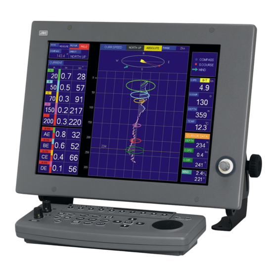
Externals of Equipment NWZ-164 LCD Monitor and NCH-603E Key Board NJC-28/30 Signal Processor CFT-068B/067B Transducer... -
Page 12: Glossary
Glossary Tidal current direction: Direction of the current flow. "It flows and leave" direction is indicated usually. North up bearing: Bearing displayed with true north at the top of the display. Head up bearing: Bearing displayed with bow at the top of the display. A, B, C, D and E layers: Five depths at which speeds and other information are measured. -
Page 13: Table Of Contents
Contents PREFACE ........................... I ●BEFORE OPERATION● ....................II ●PRECAUTION UPON EQUIPMENT OPERATION● ..........III EXTERNALS OF EQUIPMENT ..................V GLOSSARY ........................VI 1. OVERVIEW ........................1-1 1.1 F ........................ 1-3 UNCTION 1.1.1 Function of This System ..................1-3 1.2 F ........................ - Page 14 3.3.4 Alarm Display, Stopping of Alarm Sound and Adjusting volume ..... 3-13 3.3.5 Setting of Display Color in Shoal of Fish Image and Echo Graph ....3-13 3.3.6 Eliminating Interference ................. 3-14 3.3.7 Assistance of Setting ..................3-14 3.3.8 Simple Setting and Reference Value of Measurement Setting ......3-14 4.
- Page 15 4.3 S ................4-23 PEED ISPLAY ETTING 4.3.1 Ship Speed Graph Setting ................4-23 4.4 T ................4-25 RACK ISPLAY ETTING 4.4.1 Current Numerical Value Display ..............4-25 4.4.2 Five Layer Display of Current Vector .............. 4-25 4.4.3 Own Track Display (Track Plotting) ..............4-26 4.4.4 Plot Display Setting ..................
- Page 16 7.1.5 TD Angle, Ship Speed, Draft and Delay Correction ........... 7-6 7.1.6 Data Processing Setting ..................7-7 7.1.7 LAN Output Setting ..................7-7 7.1.8 Alarm Display Setting ..................7-8 7.1.9 Self Test Display ....................7-8 7.1.10 Total Distance/Master Reset/User Menu Registration ........7-8 7.2 I ......................
- Page 17 12.1.1 Standard Menu ..................... 12-3 12.1.2 Selection Frame Menu .................. 12-9 12.2 C ..................12-14 ONNECTION IAGRAM 12.3 S ....................12-16 PARE ARTS...
- Page 19 Index Overview …………………………………… Name and Functions ……………………… Operation Method …………………………. Operation …………………………………… Measurement Alarm ………….……………. How to See Display ……………………….. Confirming the Operation of Equipment … Maintenance and Check ………………….. Trouble and After-sales Service ………….. 10 Disposal …………………………………….. 11 Specifications ………………………………. 12 Others ……………………………………….
-
Page 21: Overview
1. Overview... -
Page 23: Function
The shoal of fish screen displays the shoal of fish image in four directions on division into four, division into two, and one screen. The JLN-650/652 displays the same image as a usual fish finder can be displayed in sensitivity and the bubble cancellation with the knob. -
Page 24: Features
Function of Profile Display The current in 100(JLN-650)/50(JLN-652) layers or less is in real time displayed in the graph. In the ・ ellipse graph display, the current speed of the current in 100(JLN-650)/50(JLN-652) layers is confirmed and can the twist and swinging of the current can visually be confirmed by displaying the vector on the ellipse. -
Page 25: Composition
1.3 Composition The composition unit and option unit are shown in the following tables; Composition unit JLN-650 Description Model Name Q’ty Remarks LCD Monitor NWZ-164 15-inch LCD Signal Cable 5m include Power Cable 5m include Signal Processor NJC-28 Keyboard NCH-603E... - Page 26 JLN-652 Description Model Name Q’ty Remarks LCD Monitor NWZ-164 15-inch LCD Signal Cable 5m include Power Cable 5m include Signal Processor NJC-30 Keyboard NCH-603E Cable 5m Transducer NKF-779 Cable 25m JLN-652 Stuffing Tube MPJD30076 Transducer CFT-067B Spare Parts 7ZXNA3002 Fuse:4 Piece Instruction Manual 7ZPNA3204C English version...
-
Page 27: Construction
1.4 Construction The outline drawing of the unit is shown in below; Model Name Description Remarks NWZ-164 LCD Monitor Outline Fig. 1.4-1 ・・・・・・・・・ NCH-603E Keyboard Outline Fig. 1.4-2 ・・・・・・・・・ NJC-28/30 Signal Processor Outline Fig. 1.4-3 ・・・・・・・・・ Transducer NKF-774 Transducer Outline Fig. - Page 28 WARNING LABEL 警告 WARNING このカバーをはずすな 感電の恐れあり HIGH VOLTAGE DO NOT REMOVE THE COVER Unit: mm Fig.1.4-1 NWZ-164 LCD Monitor Outline...
- Page 29 Fig. 1.4-2 NCH-603E Keyboard Outline...
- Page 30 WARNING LABEL 警告 WARNING このカバーをはずすな 感電の恐れあり HIGH VOLTAGE DO NOT REMOVE THE COVER Fig. 1.4-3 NJC-28/30 Signal Processor Outline 1-10...
- Page 31 Fig. 1.4-4-1 NKF-774 Transducer with Stuffing Tube 1-11...
- Page 32 Fig. 1.4-4-2 NKF-779 Transducer with Stuffing Tube 1-12...
- Page 33 Fig. 1.4-5-1 NKF-775 Transducer Outline 1-13...
- Page 34 Fig. 1.4-5-2 NKF-780 Transducer Outline 1-14...
- Page 35 (200Pulse/nm) (NMEA0183) MVVS-2C MVVS-2C Analog Signal Wind Sensor (±10V) (NMEA0183) Signal Processor NJC-28 MVVS-2C MVVS-2C Temp. Sensor JRC Format Signal (NMEA0183) (UART) MVVS-2C Fish Finder, Sonar Trigger Signal 0.6/1kV DPYC-2.5 Ship’s Main AC100---230V Transducer cable (25m attached) Bottom Mount Transducer...
- Page 36 TTYCS-1 or MVVS-2C MVVS-2C NJC-30 Analog Signal Temp. Sensor (±10V) TTYCS-1 or (NMEA0183) TTYCS-1 or MVVS-2C MVVS-2C JRC Format Signal Fish Finder, Sonar (UART) Trigger Signal Transducer cable (1m attached) DPYC-2.0 Ship’s Main DC24V Matching Box Transducer cable NQD-2422 Rectifier Ship’s Main...
-
Page 37: Name And Functions
Name and Functions... -
Page 39: Name And Functions Of Keyboard
2.1 Name and Functions of Keyboard ⑯ ④ ⑦ ① ⑥ ⑮ ⑪ ⑫ ② ⑭ ⑬ ③ ⑨ ⑤ ⑩ ⑧ Fig. 2.1-1 Keyboard / STC and GAIN Knob for Fish Finder Name Function The power supply of this device is turned on. ①... -
Page 40: Display And Name Of Screen
2.2 Display and Name of Screen 2.2.1 Tidal Current Display The current screen mainly displays current direction and speed for the subculture of the current in five layers under the surface of the water, the ship speed and the course. The current screen is displayed with the [CURR] key. - Page 41 Left part of the screen Mode : Usually, set measurement (for current measurement) *101 Screen : Select from current 1/current 2/current 3. Compass : Displaying head up bearing *102 Bearing Standard: The bearing standard of the current and the ship speed vector is set and displayed.
- Page 42 2) Current 2 screen (numeric display): Example of display Mode Ship Speed・Course Screen / Compass Doppler S.Speed: Bottom Tracking / Water Tracking / Bearing Standard GPS Ship Speed: GPS Wind Direction Wind Speed Total Distance Trip/Timer Bottom Depth Water Temperature and it’s Graph Relative Current: Absolute Current:...
- Page 43 Right part of the screen Ship Speed・Course: The ship speed and course are displayed. Doppler: The bottom tracking or water tracking ship speed measured with the current meter is displayed. GPS: The ship speed from the navigation equipment such as GPS is displayed.
- Page 44 3) Current 3 screen (echo display): Example of display Ship Speed・Course Doppler S.Speed: Mode Bottom Tracking Screen Water Tracking Wind Direction Water Compass GPS Ship Speed: GPS Wind Speed Temperature Bearing Standard Bottom Depth Own Ship Position Absolute Current: Depth Current Speed Cursor Position: Echo table and...
- Page 45 Right part of the screen Ship Speed・Course: The ship speed and course are displayed. Wind Direction/Wind Doppler: The bottom tracking or water Water Temperature: Speed: tracking ship speed measured with the The water temperature is displayed. It displays wind direction current meter is displayed.
-
Page 46: Ship Speed Display
2.2.2 Ship Speed Display The ship speed screen mainly displays the course and the speed of the ship. The ship speed screen is displayed with the [SHIP] key. There are two screens (ship speed 1 and ship speed 2(graphical display), and the screen changes into the ship speed screen whenever the [SHIP] key is pushed. - Page 47 Right part of the screen Fore/After・Port/Starboard Ship Speed: The speed of the ship is displayed based on the prow dividing into two (fore/after and port/starboard). *202 Ship Speed・Course: ・Selecting frame menu display: 12.1.2-(5) The ship speed and course are displayed. Doppler: The bottom tracking or water tracking ship speed measured with the current...
-
Page 48: Track Plot Display
2.2.3 Track Plot Display The own tracks are displayed on the screen, and the current direction/speed vector of five layers are displayed on the track. The track screen is displayed with the [PLOT] key. It is possible to display it by extending the range of the track display in the menu. - Page 49 Right part of the screen Own Track Display (Track Plot): The track is plotted on the screen based on information of the GPS location or Course Vector Own Ship the ship speed by Doppler data. *311 ・Selecting frame menu display: Cursor and 12.1.2-(15) Cursor Position Data...
-
Page 50: Graph Display
2.2.4 Graph Display Current direction/speed, depth, ship speed, water temperature (*401), and wind direction/speed (*402) from the past to present of the current in five layers are displayed. The passage screen is displayed with the [GRAPH] key. It is possible to display it by enlarging the display range in the passage graph by the menu. - Page 51 Right part of the screen Current/Depth Graph: The current is displayed right within the range of depth of the vertical axis, and depth is displayed left. Current Graph: The history of the time of the current vector on each intersection of the horizontal axis and the depth value of the graph is displayed.
-
Page 52: Fish Finder Display
2.2.5 Fish Finder Display The fish finder screen converts the reflection signal of the supersonic wave launched in four directions into 16 colors according to strength, and displays the water inside. Because the supersonic wave is turned in four directions (Fore Starboard, Fore Port, After Starboard, After Port), each detection result can be displayed by division (four screens) into four, and, in addition, two screens and one screen displays can be selected. - Page 53 Upper part of the screen Direction of Display Beam: Mode: It sets to the measurement The selecting display beam is usually. *101 displayed by a red arrow now. Screen:Selecting from FISH 1/FISH *511 2/FISH 3 Water temperature: ・Selecting frame menu display: ・Selecting frame menu display: Water temperature is 12.1.2- (19)
-
Page 54: Tidal Profile Display
2.2.6 Tidal Profile Display The current (direction/speed) to depth layer (*601) from the surface to bottom of the sea is displayed in the graph by the depth of each 2m. Five current layers of a numeric display are seen, and the current in about 50 layers is seen in depth from 12m in depth to 112m in case of addition, for instance, 150m in depth it and because the graph is displayed at the same time, can the twist of the current from the surface to bottom of the sea and the change in swinging can be seen. - Page 55 Right Part of the screen Depth: The sea bottom depth is displayed. *109 ・ Selecting frame menu display: 12.1.2-(9) Ship Speed・Course: The ship speed and course are displayed. Water Temperature: Doppler: The water temperature is displayed. *108 The bottom tracking or water tracking ship ・Selecting frame menu display: 12.1.2-(7) speed measured with the current meter is displayed.
- Page 56 2) Profile 2 screen (ellipse graph display): Example of display The current direction and current speed in 50 layers or less are displayed on an ellipse graph by the vector. Moreover, because the deflection angle and the horizontal angle of the view point that looks down at an ellipse graph can be changed, the twist of the current and the change in swinging can be seen so that it may peep in the sea.
- Page 57 Right part of the screen Ellipse Graph Flow Speed Range: Profile Current; Current Direction/Current Speed: The flow speed range of the graph is The current is displayed in the vector in an ellipse graph. set by the menu. *620 The length of the vector shows the speed of the Current, ・Selecting frame menu display: and the direction of the vector shows the direction of the 12.1.2- (22)
- Page 58 3) Profile 3 screen (Upwelling flow): Example of display The Upwelling flow in 50 layers or less are displayed in the graph. Ship Speed・Course: Doppler S. Speed: Bottom Tracking/ Mode/Screen Water Tracking Bottom Compass/Bearing Water Wind Direction GPS Ship Speed: GPS Depth Temperature Wind Speed...
- Page 59 Lower part of the screen Profile Current Upwelling Flow Display of Current in the vertical direction Flow Speed Range: The flow speed range of the graph is set by the menu. ・Selecting frame menu display: 12.1.2- (23) The history time Range of Upwelling Flow is set by the menu.
-
Page 61: Operation Method
Operation Method... -
Page 63: General Flow Chart
3.1 General Flow Chart CAUTION ●Do not put the thing on the keyboard. Especially, when a hot thing is put on the keyboard, it might cause the transubstantiation. ●Please do not give the strong impact to the knob of the keyboard. It might cause the breakdown. -
Page 64: Power On And Date/Time Setting
3.1.1 Power ON and Date/Time Setting CAUTION ● Execute to turn on the power supply again after thirty seconds or more have passed since the power supply was intercepted. ●The current meter might power off or malfunction when the ship power supply failure while the current meter is working. -
Page 65: Current Measuring Depth Setting
3.1.3 Current Measuring Depth Setting Operation Procedure The depth of the measured current is set. It set on all screens except fish finder screen. 1) "Setting of the depth of the current measurement layer" menu (*1) is displayed by the [DEPTH] key. -
Page 66: Menu Composition
3.2 Menu Composition In this device (current meter), the function to operate by the panel key and the knob of the keyboard is provided, and, besides, the function to operate on the menu is provided.. The current meter can be used more functionally by doing the setting to be suitable for the purpose. -
Page 67: Standard Menu Composition
3.2.1 Standard Menu Composition Setting at Installation NMEA0183 Input 1. Heading Sensor Initial Setting 2. Speed Course Sensor Outline of the Operation 3. Water Temp. Sensor Menu Screen 【MENU】 【ENT】 Installation Setting ≫ 【ENT】 4. Wind Anemometer Language: Display Mode Depth Unit 日本語/English Software Version... -
Page 68: Selection Frame Menu Composition
3.2.2 Selection Frame Menu Composition Display Screen Selection Frame Menu Title Ref. of Menu Item Display Screen No. Selection frame is displayed by【□】 key and move Selection frame menu is key. displayed with the 【MENU】 End by 【□】key. key. [CURR ]Screen Disp. -
Page 69: Basic Operation Of Menu
3.2.3 Basic Operation of Menu 1) Standard menu How to open menu The menu display opens pushing the [MENU] key. *The menu screen is displayed at the center of screen. *The menu Screen is displayed by the half penetration, and can select the permeability. (*1) Menu Screen How to close menu... - Page 70 2) Selection frame menu Ex.: [CURR]1 Screen "Selection frame" (outside frame with square yellow bold line) is Circle Graph Display displayed on the screen being displayed now. It moves to the table and the graph where it wants to set this "Selection frame". Under such a condition, when the [MENU] key is pushed, a set menu corresponding to the part selected by "Selection frame"...
- Page 71 3) Depth setting menu Ex.: [CURR] 1 Screen Ex.: [FISH] 3 Screen Circle Graph Display Fig. 3.2.2 [CURR] Screen When the current measurement data (All screens except the [FISH] screen correspond) is displayed, the depth setting menu of the current measurement layer in the A-E layer is displayed.
-
Page 72: Preparation For Operation
3.3 Preparation for Operation 3.3.1 Adjusting Screen Brightness Operation Procedure Confirm that there is a power supply. The brightness knob under the right of the display is rotated, and it adjusts in the state to see the screen easily. [Brightness] Knob The whole of the screen lightens if the [brightness] knob is turned clockwise. -
Page 73: Alarm Display, Stopping Of Alarm Sound And Adjusting Volume
3.3.4 Alarm Display, Stopping of Alarm Sound and Adjusting volume 1) The alarm display and the alarm sound are stopped when alarm is generated, and it is canceled an alarm. Operation Procedure Push the BUZZER key. The alarm display and the alarm sound stop. 2) The alarm sound volume is adjusted. -
Page 74: Eliminating Interference
3.3.6 Eliminating Interference It is possible to set it only to the [FISH] screen. The interference elimination is used to remove the acoustic noise that enters from another ship and the noise appearing at random. Use it by 'Off' usually., and make it to 'On' When you want to reduce the effects of noise. -
Page 75: Simple Setting And Reference Value Of Measurement Setting
3.3.8 Simple Setting and Reference Value of Measurement Setting The reference value of a measurement setting according to situation is introduced. Note: By setting a reference value, it does not guarantee that a situation improves. In the tidal current measurement mode (all screens except fish finder mode) Filter setting using STC knob is possible. - Page 76 Introduce reference values for setting when not using simple setting The following configuration changes is the setting that priority to the response compared to the standard setting. This setting is the setting that assumes as much follow-up and JLN628(std.. or short.). Adjustment of response (stability) is, please go tide ava.
-
Page 77: Operation
Operation... -
Page 79: Measurement Setting And Current Display
Measurement Setting and Current Display 4.1.1 Bearing Display: 32 Point or 360° When the direction standard is set to the north up bearing, the mode of expression of the ・Function・ current direction and the course of the [CURR] screen is selected. Operation Standard Menu: [MENU] key/Menu screen/Measure setting /[ENT] key/Bearings :... -
Page 80: Direction Standard
4.1.2 Direction Standard: North up Bearing/Head up Bearing (-T / -R) The bearing standard of the current and the ship speed vector displayed on the [CURR] ・Function・ screen and others is selected. Operation Standard Menu: [MENU] key/Menu screen/Measure setting /[ENT] key/Direction ≫... -
Page 81: Absolute Current Standard
4.1.3 Absolute Current Standard: Doppler / GPS / Auto-GPS WT / Auto-WT When absolute current (*1) (current speed to ground) is measured, the ship speed data is ・Function・ set as a standard. Set the Doppler /Auto-WT /WT when the navigation equipment such as GPS is not connected. -
Page 82: Ship Speed Display
Automatic: Though ground A is usually displayed, when it becomes impossible to measure the ship speed by bottom tracking as the bottom of the sea or more depth becomes deep (about 400(JLN-650)/250(JLN-652)m(*2)), it switches to water tracking display automatically (*3). -
Page 83: Trip/Timer
4.1.7 Trip/Timer Whether the section track distance (trip) is displayed or the elapsed time (timer) is ・Function・ displayed is selected. This trip or the timer is displayed on the [CURR] screen and the [SHIP] screen. Operation Standard Menu: [MENU] key/Menu screen/Measure setting /[ENT] key/Trip・Timer: ≫... - Page 84 Measurement alarm Current speed alarm・Low: When Current speed falls below a set value (warning value), it generates an alarm. Setting alarm value [OFF, 1.0 1.5 2.0 2.5 3.0 3.5 4.0 4.5 ]kn Ship speed alarm・Low: When ship speed falls below a set value (warning value), it generates an alarm.
-
Page 85: Bottom Lock Mode
4.1.9 Setting of Bottom Tracking Maximum Depth to Seach It explores the seabed within the range of depth that is shallower than that of the depth ・Function・ value selected by the menu. And, the bottom of the sea depth is measured and tracked. The standard is set to 500m the maximum. -
Page 86: Btm Adjustment
4.1.11 BTM Adjustment: -3/-2/-1/0/+1/+2/+3/+4/+5/+6 Function The measurement depth of layer pursued according to ups and downs in bottom of the sea automatically can be adjusted. Use the +2 position usually. Operation Standard Menu: [MENU] key/Menu screen/Measure setting /[ENT] key/BTM Adjustment: ≫... -
Page 87: Tide Process
4.1.14 Tide Process: J1/J1+/J2/J2+/J3/J3+/J4/J4+/J5/J5+ Function It is a menu for servicemen. Used the J3 position usually. Operation Standard Menu: [MENU] key/Menu screen/Measure setting≫/[ENT] key/ Tide Process: J1/J1+/J2/J2+/J3/J3+/J4/J4+/J5/J5+ About current operation It is a setting item which functions on the operation of a current value. The variation in a current value becomes small so that a numerical value is large, but the influence of the following comes out. -
Page 88: Bt・Wt・Tide Average Time 1
4.1.16 Mode: 628 mode/650 mode Function It is a menu for servicemen. Use in the 650 mode Usually. Operation Standard Menu: [MENU] key/Menu screen/Measure setting /[ENT] ≫ key/Mode:628 mode/650 mode About the mode In the 628 mode, it operates by a function similar to JLN-628. - The standard of a current measurement layer is made equivalent to JLN-628, and maximum shallow layer of 2m becomes able to always display. -
Page 89: Bt・Wt Average Time 3
4.1.19 BT WT Average time 3: Short/2/3/4/5/6/7/8/9/Long Function It is a menu for servicemen. Use the 3 position usually. Operation Standard Menu: [MENU] key/Menu screen/ Measure setting /[ENT] key ≫ /BT Ave. Processing time3: Short/2/3/4/5/6/7/8/9/Long /WT Ave. Processing time3: Short/2/3/4/5/6/7/8/9/Long About BT・WT Average time 3 It is a setting similar to "BT・WT・Tide Average time1". -
Page 90: Filter Setting 1
4.1.22 Filter setting 1:A0/A1/A2/B0/B1/B2/C0/C1/C2/C3 Function The balance of the stability of a current display, accuracy, and tracking performance is adjusted. Use the B1 position usually. When it gives top priority to the tracking performance in the low current flow velocity, use the A1 position. - Page 91 4.1.24 Filter Setting 3:G0/G1/G2/G3/G4/H0/H1/H2/H3/H4 Function It is a menu for servicemen. Use the G1 position usually. Operation Standard Menu: [MENU] key/Menu screen/ Measure setting /[ENT] key ≫ / Filter Setting 3: G0/G1/G2/G3/G4/H0/H1/H2/H3/H4 About Filter Setting 3 It is a setting item which functions on the operation of a current. The action which converges a current value to 0 becomes large, so that a numerical value is large.
-
Page 92: Filter Setting 5
4.1.26 Filter Setting 5:L0/L1/L2/L3/L4/L5/L6/L7/L8/L9 Function It is a menu for servicemen. Adjust the settings. When Set of filter setting1 is A or B Use the L8 position usually. Operation MENU MEASURE SETTING FILTER SETTING 5 = L0 / L1 / L2 / L3 / L4 / L5 / L6 / L7 / L8 / L9 About Filter Setting 5 0~9 : Setting of Filter setting1 only when A or B, Adjustment is enabled. -
Page 93: Switch Speed
4.1.28 Switch Speed: -10/-5/-2/-1/0/1/2/5/10/20 Function It is a menu for servicemen. Use the 0 position usually. Operation Standard Menu: [MENU] key/Menu screen/ Measure setting /[ENT] key ≫ / Switch speed: -10/-5/-2/-1/0/1/2/5/10/20 About stabilization of current It is a setting item which functions on the operation of a current. In the following case, a setup of a current operation filter is changed to a preliminary setting group. -
Page 94: Current Display Setting
4.2 Current Display Setting 4.2.1 Current Circle Graph Setting The current circle graph is set. ・Function・ Setting items: Current speed range, Current vector display, Ship speed vector, Enlarge of graph, Wind direction arrow Operation Standard Menu: [MENU] key/Menu screen/Picture Setting / Curr [ENT] key/Tidal ≫... -
Page 95: Current Echo Graph Setting
Wind Direction Arrow (*1): Display/Non-display ・Function・ It is set whether to display the wind direction arrow on the circle graph. Display: The arrow of the example is displayed in figure. The wind blows from the ⑤ direction of the arrow. Non-display: The wind direction arrow is not displayed. - Page 96 Echo Graph Depth Range ・Function・ The depth range in the graph is set within the range of 100-500m. Refer to the example ② in Fig.4.2.2 Range setting value: [100 200 300 500] m Operation Standard Menu: Current screen setting menu/Echo Graph depth range: 100-500m Selection Frame Menu: Echo graph setting menu/ Echo Graph depth range: 100-500m Mode Selection ・Function・...
- Page 97 SN Value: High Background ・Function・ When SN is selected by the mode Color selection of the echo graph setting, it Week sets. When the S/N value of the echo is higher than that of the set level, it displays by the permeability 0%(no penetration).
-
Page 98: Current Measurement Layer Depth Setting
Cursor position echo table: Refer to Fig. 4.2.2- ① "Cursor position echo" displays information on horizontal cursor in the echo graph. ④ The horizontal cursor moves up and down with the key on the keyboard. ▲▼ ⑪ Depth (Ex.:200 m): Depth at the horizontal cursor position is displayed. When a shoal of fish and a multiple reflection, etc. -
Page 99: Ship Speed Display Setting
4.3 Ship Speed Display Setting 4.3.1 Ship Speed Graph Setting The ship speed graph is set. ・Function・ Setting item: Ship speed range, Ship speed display (Element/Deflection), Recording time Operation Standard Menu: [MENU] key/Menu screen/Display setting /[ENT] key/Ship speed ≫ display /[ENT] key/Ship speed display setting menu ≫... - Page 100 Recording Time The record time of the elapsed (ship speed) graph of [SHIP] 2 screens is set. ・Function・ Recording time: It is selected from [30 60 120 240] mimute Operation Standard Menu: Ship speed display setting menu/Recording time: 30 mimutes Selection Frame Menu: Ship speed・Course graph menu/ Recording time: 30 mimutes Ship speed elapsed graph Upper Side: Starboard Speed...
-
Page 101: Track Plot Display Setting
4.4 Track Plot Display Setting 4.4.1 Current Numerical Value Display: Display / Non-display ON or OFF of A numeric display of "Current direction and Current speed" displayed at the ・Function・ left of the screen can be selected. Operation Standard Menu: [MENU] key/Menu screen/Display setting /[ENT] key/Plot screen ≫... -
Page 102: Own Track Display (Track Plotting)
4.4.3 Own Track Display (Track Plotting) The track of the ship is plotted on the screen based on the location information of GPS or ・Function・ speed information on the ship of the Doppler data. The ship position is displayed on the plot screen by the ship shape mark. Moreover, the speed and the course vector of the ship are displayed by a white solid line. - Page 103 Track Standard: Doppler/GPS The track standard is data that becomes a standard to display the ship track on the [PLOT] ・Function・ screen. This selects GPS or Doppler from the menu. When the track standard is Doppler, a numeric scale is not displayed in the latitude line and longitude lines on the [PLOT] screen.
- Page 104 Vector Display The interval of the current vector in which it displays it on the track is set. ・Function・ Whether the current vector is displayed at the rate once every times of "Storage interval" in the previous clause how many is specified. Setting value: [1/1 2 4 10 20 50] times Ex.: When the setting is 1/2, the current vector is displayed on the track at the rate once every 12 seconds for six seconds the setting of "Storage interval".
- Page 105 Current Event Mark: Display/Non-display When the display is selected, memorized past track and current vector are displayed. (*1) ・Function・ It sets to non-display usually. Operation Standard Menu: Plot screen setting menu/Current event mark: Display/Non-display Selection Frame Menu: Plot drawing menu/Current event mark: Display/Non-display ・Display and movement of cursor positional data sheet・...
-
Page 106: Graph Display Setting
4.5 Graph Display Setting 4.5.1 Current/Depth Graph Setting Current Graph: The elapsed time of the current vector of each intersection of a horizontal ・Function・ axis of the depth value and a vertical axis of the graph is displayed. The vector can be set ON/OFF according to the layer. Depth Graph: (current graph and overlay display)The elapsed time of depth is displayed. -
Page 107: Ship Speed Graph Setting
Vector Density The vector display interval in the current ・Function・ graph is selected. Setting value: [Normal High S-High] Normal: The vector is displayed on the intersection in the grid. High, S-High: The vector is displayed [Normal] [High] [S-High] between grids. ”... -
Page 108: Water Temperature Graph Setting
Ship Speed Range The maximum display value of the graph is set. ・Function・ Setting value: [ 5 10 15 20 25 30 40 ] kn The setting of the time axis is common with current/depth graph. “ ” Operation Standard Menu: Graph Picture setting menu/Ship speed range: 10 kn “... -
Page 109: Wind Direction/Speed Graph Setting
4.5.4 Wind direction/Speed Graph Setting The elapsed time of the wind direction/wind speed vector in each vertical line of the graph ・Function・ time axis are displayed. (*1) The setting of the time axis is common with current/depth graph. The vector display interval in the graph is common with current/depth graph. Refer to "Vector Density"... -
Page 110: Fish Finder Display Setting
4.6 Fish Finder Display Setting The [FISH] screen converts the reflection signal of the supersonic wave launched in four directions into 16 colors according to strength, and displays the water inside. (*1) Because the supersonic wave is turned in four directions (fore of the starboard, fore of the port, the after of the starboard, and the after of the port), another, two screens, and one screen displays that display each detection result by division (four screens) into four can be selected, too. -
Page 111: Screen Display Setting
[FISH 3] Screen Display When you select the beam direction displayed on three shoal of fish screens (four ・Function・ direction display). Setting value: [ 4 ] The beam direction in the hatching part is selected with key as [4] and it fixes with the [ENT] key. - Page 112 Color Sample The color sample is displayed on the left end of the screen. ・Function・ Setting item: [ Display ON OFF ] The color sample is not displayed when setting to OFF. Refer to the above-mentioned "Color" for the color arrangement of color sample. Operation Standard Menu: "Fish Finder Picture setting"...
-
Page 113: Eliminating Interference
Horizontal Cursor The cursor is not displayed when OFF is set. ・Function・ Setting item: [ Display ON OFF] A horizontal cursor moves with key. The display numerical value is a depth at the ▲/▼ cursor position. Operation Standard Menu: "Fish Finder Picture setting" menu/Horizontal cursor: Display ON/OFF Selection Frame Menu: "Fish Finder display"... -
Page 114: Depth Range Setting
4.6.5 Depth Range Setting This section is described 1)Depth range setting of FISH screen and 2)The range of depth is allocated to a numeric key. [FISH] screen: Depth Range Setting It changes within the range of depth corresponding to each key on the [FISH] screen when ・Function・... -
Page 115: Tidal Profile Display Setting
Selection Frame Menu: "Profile 1 graph" menu/Display Current: Absolute *1 The maximum depth in which the current can be measured is about 160(JLN-650)/100(JLN-652)m of depth or about 75% value of bottom of the sea depth. It changes by the oceanographic condition. -
Page 116: Profile 2 Graph Setting (Ellipse Display)
4.7.2 Profile 2 Graph Setting (Ellipse Display) The multilayer current data is made an ellipse graph on profile 2 screens and it displays. ・Function・ An ellipse size shows the speed of the current, and the direction of the vector shows the direction of the current. - Page 117 Multilayer Vector Density The number of the displayed multilayer vector is thinned out on ・Function・ the profile screen. It is set to 1 (1/1=100% display) usually. Setting value: [ 1/1 2 4 8 16 Display OFF ] For instance, when the multilayer current up to 200m in depth is displayed, about maximum 100 current vectors are displayed.
-
Page 118: Multilayer 3 Screens Setting (Upwelling Display)
4.7.3 Multilayer 3 Screens Setting (Upwelling Display) Function The up-and-down direction component of multilayer current data is displayed with multilayer 3 screens to 1) upwelling graph and 2) progress graph. Setting item: upwelling depth range, upwelling speed range, record time measurement depth (V, W, X, Y, Z layer) and graph partitioning Operation Standard Menu: None... -
Page 119: User Menu Setting
4.8 User Menu Setting Two kinds of (user 1 and user 2) arbitrary menu settings can be registered. ・Function・ It is possible to use it by registering what set according to the fishing method, the fishery, and the season such as ranges on the current measurement depth of layer and the [FISH] screen, and reading it if necessary. -
Page 121: Measurement Alarm
Measurement Alarm... -
Page 123: Measurement Alarm Display
5.1 Measurement Alarm Display There are two kinds of alarm; a measurement alarm and a warning alarm. When abnormality is found by the unit and the system of the equipment, a warning alarm displays "Warning message". Refer to 9.1 “Warning" for an abnormal alarm. When alarm is generated, "Measurement alarm message"... - Page 124 Measurement Alarm Message Alarm 1. When the depth of the A-E layer (absolute current measurement depth Depth alarm in of layer) is deeper than about 80% of bottom of the sea depth. which current Alarm Ex.) When the depth is 200m, current measurement depth of cannot be layer is 170m measured.
-
Page 125: How To See Display
How to See Display... -
Page 127: Absolute Current And Relative Current
6.1 Absolute Current and Relative current 6.1.1 Absolute current The absolute current shows the direction and the speed of the current to bottom of the sea (to ground). Fig. 6.1.1 is an example when the absolute current of three layers (A, B, and E) is displayed in the circle graph based on bottom of the sea among the currents in A, B, C, D, and E layer. -
Page 128: Relative Current And Standard Current Layer
6.1.2 Relative Current and Standard Current Layer Relative Current: For instance, when E layer is a standard, a relative current shows the direction and speed of the current in A layer to the current in E layer, B layer, C layer, and D layer. Moreover, each relative current is displayed as the AE layer, the BE layer, the CE layer, and the DE layer. - Page 129 ・Setting of Relative Current Standard When a relative current is measured, the based current layer is selected. ・Function・ For instance, when E layer is set to the standard layer of drum, A layer, B layer, C layer, and D layer are displayed respectively based on E layer as "AE", "BE", "CE", and "DE". Operation Standard Menu: [MENU] key/Menu screen/Measure setting /[ENT] key/Relative current...
-
Page 130: Bottom Tracking Layer
6.2 Bottom tracking layer 6.2.1 Bottom Lock (BTM) ・Function・ Absolute Current of Sea Bottom: The measurement depth of layer changes automatically according to ups and downs in bottom of the sea if the measurement depth of E layer is set to BTM (bottom lock). (*1) This is convenient for the measurement of the bottom of the sea layer. -
Page 131: Surface Automatic Tracking Layer
6.3 Surface Automatic Tracking Layer 6.3.1 Top Lock (TOP) Function Absolute Current of surface: If a current measurement layer depth setting of A layer is set to a top lock (TOP), according to a transmitting pulse width setting and a surface measurement condition, the measurement layer depth is changed automatically. -
Page 133: Confirming The Operation Of Equipmen
Confirming the Operation of Equipment... -
Page 135: Setting When Installing
7.1 Setting when Installing This paragraph is described the content done when service person installs the equipment. It is work necessary to measure accurately, and to display it correctly. After completing the installation, all work checks whether to be done properly as it is an instruction. Especially, confirm whether the mistake of the connection of the cable, the state of the installation of each equipment, and the processing of the cable shield braid are correctly done. -
Page 136: Unit Setting
3. Water Temperature Sensor It selects it from Disconnection/Connection. (*1) ・Function・ When Disconnecting it, the water temperature data and the water temperature graph are not displayed on the display, and the part of it becomes blank. Operation Standard Menu: “Installation setting” menu/3.Water temperature sensor: Disconnection 4. - Page 137 Movement of Menu Screen The display position can be moved in "Selection frame menu". (*1) ・Function・ Operation When "Selection frame menu" is displayed, the menu panel moves whenever the [PLOT] key on the keyboard is pushed. Movement zone: Fixed position → Upper the left → Upper the right → Under the right →...
- Page 138 7.1.5 TD Angle and Ship Speed Correction Transducer Angle Correction It is possible to set within the range of [-20.0 - ±00.0 - +20.0] degree. Standard: ±00.0 ・Function・ The numerical value changes into the direction of the minus with key in 0.1 degrees step, and changes into the direction of the plus with key in 0.1 degrees step.
-
Page 139: Data Processing Setting
7.1.6 Data Processing Setting GPS Time Delay It sets within the range of [0 - 7 - 12 ]. Standard: 7 ・Function・ The numerical value changes into the direction of the minus with key in 1 step, and changes into the direction of the plus with key in 1 step. -
Page 140: Alarm Display Setting
7.1.8 Alarm Display Setting Alarm (Measurement Alarm Display) It selects from [Display ON/OFF]. It sets to the Display ON usually. ・Function・ When the measurement alarm (depth, ship speed, current, water temperature (*1), and the wind speed (*1)) is generated, information on "Measurement alarm" is displayed on the screen if it sets to the display. -
Page 141: Initial Setting
7.2 Initial Setting Service person must execute this paragraph after confirming the normal performance by the check after equipment is installed. CAUTION Do not adjust it excluding special service person. It might cause operation to become unstable if a wrong setting is done. -
Page 142: Selecting Of Measurement/Dummy Mode
7.2.3 Selecting of Measurement/Dummy Mode Display Mode It selects it from Measurement/Dummy. ・Function・ Measurement: It operates as a standard current measurement equipment. Set to the measurement usually. Dummy: To confirm the operation of the equipment, ship speed and the current data of the dummy are displayed. -
Page 143: Memory Data Copy And Erase
7.2.5 Memory Data Copy and Erase Memory Data Copy and Erase When ≫ is selected, and the [ENT] key is pushed, submenu "Memory data copy and ・Function・ erase" is displayed. About Memory Data: A present menu setting value, and it is a ship track, and the current vector of the track screen in "SSD". - Page 144 3) The memory data of the track etc. copied onto the USB external memory is written to new SSD(Software Ver.). ①The USB external memory to which the memory data is copied by 2) leaves insertion in USB2, and replaces SSD. (*1)". (*2) ②[Memory data copy and erase: ≫] is selected from main menu/”Initial setting”...
-
Page 145: Maintenance And Check
Maintenance and Check... -
Page 147: General Maintenance
8.1 General Maintenance CAUTION Never attempt to check or repair the inside of the equipment. Checking or repair by an unqualified person may cause a fire or an electric shock. Contact our head office, or a nearby branch or local office to request servicing. -
Page 148: Countermeasure To Abnormality And Trouble
8.1.2 Countermeasure to abnormality and trouble Stop using, and contact shop, agency or our each branch, office, and liaison office that purchases it at the following symptom. Abnormality and breakdown symptom 1) The screen doesn't reflect. The power supply doesn't enter. Anything doesn't appear of the color etc. -
Page 149: Trouble And After-Sales Service
Trouble and After-sales Service... -
Page 151: Warning
9.1 Warning There are two kinds of warning (measurement alarm (*1) and a warning). When the abnormal alarm message is displayed, the current data or the shoal of fish image cannot be correctly measured. Stops using and then contact shop, agency or our each branch and office that purchased it when the symptom is not repaired even if it treats it according to the message. - Page 152 Warning: 1-01~2-15 Remarks Warning message; 1. It displays until erasing it by manually when Warning the warning message is appeared once. Date :Year Month Day 14:06 2. The alarm sounds at the same time for about Warning No. :2-04 30 seconds. Situation :”USB Communication”...
- Page 154 Warning Contents Countermeasure Message Warning No. Display Control Unit 4-09 Setting data reading error Please reboot after having switched it off once. 4-10 Course plot data reading error. Does not “CF card 2” come off? 4-11 Total distance run or trip data, Please carry out the handling of the CF card after reading error.
-
Page 155: Self Test
9.2 Self Test 9.2.1 Self Test Screen The state of the equipment unit and the system is always observed. The result is displayed ・Function・ on the self test screen. When "Warning" is displayed, whether abnormality is found in addition can be confirmed on the self test screen. - Page 156 Remarks Self Test Item Results. Signal Level Monitor 3-21 ――― ――― 3-22 Noise -FS mV Less than 0.03mV 0.0060 3-23 Noise -AP mV 0.0060 3-24 Noise -FP mV 0.0060 3-25 Noise -AS mV 0.0060 The horizontal cursor is 3-26 BT Level FS Refer to Current 3 Picture set to the sea bottom in 3-27...
-
Page 157: Warning History Screen
9.2.2 Warning History Screen The warning history screen is displayed from the submenu of the self test screen. ・Function・ 100 histories or less of past "Warning" are displayed on the warning history screen. Operation Standard Menu: “Installation setting” menu/Self Test≫/[ENT] key/Self Test screen /Warning history≫(Upper part)/ [ENT] key/Warning history screen Number: It is a serial number. -
Page 158: After-Sales Service
9.3 After-sales Service 9.3.1 About The Stock Periods of Repair Parts After discontinuance of manufacturing, the stock of performance parts (parts necessary to have the function of the product) for the repair of this product are 10 years. 9.3.2 Notes When Repair is requested Is it "Breakdown"? Examine "Chapter 8 Maintenance and Check, Chapter 9 Trouble and After-sales Service"... - Page 159 JLN-650 / 652 Current Meter Malfunction Confirmation List (Asking) Please contact about the repairing or ordering, and after confirming and filling in the following item. Please inquire to the mother ship, and fill it in as accurately as possible when there is an uncertain item upon filling in.
- Page 160 9-12...
-
Page 161: Disposal
Disposal 10-1... - Page 162 10-2...
-
Page 163: Disposal Of This Product
10.1 Disposal of This Product Please process it according to the ordinance of the local government that has jurisdiction over the abandoned place or the rule when you abandon this device. This device doesn't use the battery. 10.2 About Chinese Version RoHS JLN-652... -
Page 165: Specifications
Specifications 11-1... - Page 166 11-2...
-
Page 167: General Specification
:2 axis dual beam pulse Doppler Frequency JLN-650 :125kHz JLN-652 :240kHz Display / Resolution :15”color LCD, 1024X768 pixels (XGA) Power supply JLN-650 100 - 230VAC -10% +10%: JLN-652 24VDC -10% +30% Power consumption :Less than 270W Environmental condition :Temperature:-15℃~+55℃/Humidity:Less than 93% at +40℃... -
Page 168: Main Performance
; Proprietary Code Distance Output: ② Distance Run contact Signal 200 pulse/nm [Signal name on terminal:NMEA OUT1~4 (4 circuits)] JRC Output : ③ JRC format Signal [Signal name on terminal:JRC OUT] Trigger Output: ④ Transmission trigger For interference prevention. 11-4... -
Page 169: Mechanical Specification
11.1.4 Mechanical Specification 1) Construction/Mass LCD Monitor : Desk-top, Flush-mount/3.7kg/IP45 / Waterproof grade Signal processor : Wall hanging/16kg/IP01 Keyboard : Desk-top, Flush-mount /1kg/IP22 Transducer : Submerged/25kg (include cable)/IP68 2) Outline Size LCD Monitor : 298mm (H) x 395mm (W) x 65mm (D) (Not included brightness knob and optional stand.) Signal processor : 423.5mm (H) x 326.8mm (W) x 257.4mm (D) -
Page 171: Others
Others 12-1... - Page 172 12-2...
-
Page 173: Menu Table
12.1 Menu table 12.1.1 Standard Menu (1) Menu MENU Japanese or English display is selected. ・LANGUAGE/言語 日本語 ENGLISH The color arrangement of the screen of daytime and the ・BRIGHTNESS HIGH LOW BACK COLOR SETTING≫ night is set. Alarm is stopped with the [BUZZER] key. ・ALARM VOLUME OFF 1 When GPS is connected, it is not necessary to set. - Page 174 Standard Menu (7) MENU / INITIAL SETTING ≫ INSTALLATION INSTALLATION SETTING SETTING NMEA0183 INPUT SETTING ・1.HEDING SENSOR DISCON. GPS COMPASS GYRO OTHERS Refer to 7.1 “Setting When Installing”. ・2.SPEED/COURSE SENSOR DISCON. GPS GPS COMPASS OTHERS ・3.WATER TEMP. SENSOR DISCON. CONNECT ・4.WIND ANEMOMETER DISCON.
- Page 175 (10) MENU / MEASURE SETTING ≫ MEASURE SETTING ・S.SPEED DISPLAY DOPPLER Refer to 4.1 “Measurement Setting and Current Display”. ・SYSYTEM MODE AUTO MANUAL.W.T MANUAL.B.T ・BEARINGS N・E・S・W 360° ・DIRECTION STAND. NORTH UP HEAD UP-T HEAD UP-R ・ABSOLUTE CURRENT STANDARD DOPPLER GPS Auto-GPS WT Auto-WT ・RELATIVE SURRENT STANDARD A B C D E ・TRIP/TIMER...
- Page 176 Standard Menu (11) ALARM AND GRAPH SETTING MENU / MEASURE SETTING ≫ ALARM AND GRAPH ・C.SPD ALARM・L OFF kn :SELECT WITH SETTING ≫ ・S.SPD ALARM・L OFF kn :SELECT WITH ・BOTTOM DEPTH ALARM・S OFF 60 m :SET WITH KEY Refer to 4.1.8 “Alarm and Graph Setting”. ・TIMER ALARM OFF 1:00 1:30 2:00 2:30 h ・TRIP ALARM...
- Page 177 Standard Menu (16) MENU / PICTURE SETTING / SHIP SPEED ≫ SHIP SPEED PICTURE SETTING S.SPEED GRAPH SETTING Refer to 4.3 “Ship Speed Display Setting”. ・S.SPEED RANGE 5 10 15 20 25 30 40 kn ・S.SPEED PICTURE ELEMENT VECTOR ・RECORD TIME 30 60 120 240 min ・MENU DISPLAY DISPLAY...
- Page 178 Standard Menu (20) FISH FINDER DEPTH RANGE SETTING :SETTING WITH NUMERICAL KEY DEPTH ・1 ・2 Refer to 4.6.5 “Depth Range Setting”. ・3 ・4 120 m ・5 160 m ・6 200 m ・7 250 m ・8 300 m ・9 350 m ・0 400 m ・MENU DISPLAY...
-
Page 179: Selection Frame Menu
12.1.2 Selection Frame Menu (1) DISP. MODE / PICTURE / DIRECTION MODE □ / [DISP. MODE / PICTUER / DIRECTION. ・DISPLAY MODE MEASUREMENT DUMMY MODE] SELECTING / MENU ・DIRECTION STAND. NORTH UP HEAD UP ・PICTURE SETTING CURR≫ SHIP≫ PLOT≫ GRP≫ FISH≫ PRO≫ Refer to 4.1 “Measurement Setting and Current ・BRIGHTNESS HIGH... - Page 180 Selection Frame Menu (6) TRIP / TIMER AND ALARM □ / [TRIP / TIMER AND ALARM] SELECTION / ・TRIP / TIMER TRIP TIMER MENU ・TIMER ALARM OFF 1:00 1:30 2:00 2:30 h ・TRIP ALARM OFF 1:00 2:00 3:00 4:00 h Refer to 4.1.8 “Alarm and Graph Setting”.
- Page 181 Selection Frame Menu (14) SHIP SPEED GRAPH □ / [SHIP SPEED GRAPH] SELECTION / MENU ・S. SPEED RANGE 5 10 15 20 25 30 40 kn ・S. SPEED PICTURE ELEMENT VECTOR Refer to 4.5.2 “Ship Speed Graph Setting” ・RECORD TIME 30 60 120 240 min ・S.
- Page 182 Selection Frame Menu (19) FISH FINDER DISPLAY □ / [FISH FINDER DISPLAY] SELECTION / MENU ・RANGE SETTING ≫ ・DISPLAY BEAM :SELECT WITH Refer to 4.6 “Fish Finder Display Setting”. ・COLOR A B C D ・BACK COLOR STND BLK D.BLU GRY WHT ・COLOR SAMPLE DISP ON ・CHART SPEED...
- Page 183 Selection Frame Menu (23) UPWELLING CURRENT GRAPH □ / [PROFILE 3 GRAPH] SELECTION / MENU ・UP.CURR.DEPTH RANGE 100 200 300 500 m ・UP.CURR.SPEED RANGE 1 2 4 kn Refer to 4.7.3 “Profile 3 graph Setting”. ・GRAPH TIME SCALE 10 30 60 min DEPTH SETTING ・V LAYER DISP OFF...
-
Page 184: Connection Diagram
12.2 Connection Diagram JLN-650 Connection Diagram 12-14... - Page 185 JLN-652 Connection Diagram 12-15...
-
Page 186: Spare Parts List
12.3 Spare Parts List 12-16... - Page 187 JLN-652 JLN-652 7ZXNA3002 7ZXNA3002 12-17...
- Page 190 Not use the asbestos For further information,contact: URL Head office : http://www.jrc.co.jp/eng/ Marine Service Department : msc@jrc.co.jp e - mail One - call : +81-50-3786-9201 ISO 9001, ISO 14001 Certified CODE No.7ZPNA3204D NOV. 2016 Edition 4...
Need help?
Do you have a question about the JLN-650 and is the answer not in the manual?
Questions and answers