Advertisement
Quick Links
Total solder points: 170
Difficulty level:
beginner 1o 2þ 3o 4o 5oadvanced
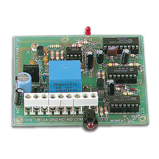
CODELOCK RECEIVER
K6707
Features:
þ Easy to build: no coils to be made!
þ Operates in conjunction with the K6706 two channel transmitter.
þ 8.748 possible codes.
þ Range of the transmitter/receiver: +/-30m.
þ LED on/off indication.
þ LED receiving level indicator.
Specifications :
þ Relay output: 10A toggle or momentary contact.
þ Separate output to switch car alarm on or off.
þ Power supply: 2 x 9VAC or 12 to 16VDC / 100mA max.
þ Dimensions: 76 x 84mm / 3 x 3,4"
* modifications reserved.
ILLUSTRATED ASSEMBLY MANUAL
H6707IP-2
Advertisement

Subscribe to Our Youtube Channel
Related Manuals for Velleman K6707


Summary of Contents for Velleman K6707
- Page 1 Total solder points: 170 Difficulty level: beginner 1o 2þ 3o 4o 5oadvanced CODELOCK RECEIVER K6707 Features: þ Easy to build: no coils to be made! þ Operates in conjunction with the K6706 two channel transmitter. þ 8.748 possible codes. þ Range of the transmitter/receiver: +/-30m.
- Page 2 VELLEMAN Components NV Legen Heirweg 33 9890 Gavere Belgium Europe www.velleman.be www.velleman-kit.com...
- Page 3 Assembly hints 1. Assembly (Skipping this can lead to troubles ! ) Ok, so we have your attention. These hints will help you to make this project success- ful. Read them carefully. 1.1 Make sure you have the right tools: •...
- Page 4 MOUNTING SEQUENCE ! REMOVE THEM FROM THE TAPE ONE AT A TIME ! Velleman hereby certifies that the device K6707 meets the essential requirements and all other relevant stipulations of directive 1999/5/EG and 1995/5/EC. For the complete conformity declaration check out :...
- Page 6 Construction NOTE : By using the jumpers, the receiver can be set up for two output possibilities: 1. The output is on while the transmitter is pressed (MOMENT), this is mostly used for operating a door lock, garage door etc. 2.
- Page 7 Construction 3. Diodes 6. Capacitors Watch the polarity ! C... D... CATHODE q C1: 2pF(2p2) q D1 : 1N4148 q C2: 2pF (2p2) q D2 : 1N4148 q C3: 22pF q D3 : 1N4148 q C4: 82pF q D4 : 1N4148 q C5 : 330pF (331) q D5 : 1N4148 q C6 : 330pF (331)
- Page 8 Construction 8. Capacitors. 11. Capacitive trimmer Watch the polarity ! CV... C... q C10 : 1µF q CV1 : 5pF (5p5) q C11 : 1µF q C12 : 1µF q C13 : 1µF 12. Voltage regulator q C14 : 1µF C15 : 470µF VR...
- Page 9 (check the position of the notch) PIN 1 IC... q IC1 : UM3758-120A q IC2 : RV4558 - LM258 - 2904 q IC3 : CD4013 q IC4 : CD40106 16. Sticker Affix the supplied sticker to the housing. Velleman 433,92 MHz SRFCE...
- Page 10 Personal code 17. Create your code You can select your own code for a transmitter/receiver com- bination. There is a 9 row jumper island located directly next to IC1 for setting the code. The code is set by connecting one or more code points to a neighboring ‘+’ or ‘-‘ point using the small jumpers.
- Page 11 Test & set-up 18. Test and set-up IMPORTANT: • A plastic screwdriver (including plastic blade) is needed to tune the transmitter or receiver. This is supplied with the receiver. • The transmitter must be in its housing with the cover off. •...
- Page 12 Connection 19. Connection 1. Connection to DC voltage : 12 ... 16vdc K6707 Fig. 1.0 E.g. : car battery 2. Connection to AC voltage : 9VAC MAINS 9VAC K6707 TRANSFO Fig. 2.0 E.g. : 2 x 9VAC / 100 mA Transformer 3.
- Page 13 Connection 4. Connection to the k3504 car alarm : DOOR LOCK SYSTEM K6707 K3504 ACCU Fig. 3.0 For connection to the K3504 car alarm the DIS points of both circuits must be connected together. In this case the "DIS" con- nection of the car alarm must not be connected to the contact lock.
- Page 14 PCB layout.
- Page 15 Diagram Diagram...
- Page 16 Modifications and typographical errors reserved © Velleman Components nv. H6707IP - 2002 - ED2...
Need help?
Do you have a question about the K6707 and is the answer not in the manual?
Questions and answers