
Related Manuals for Dolby Laboratories Lake LPD


Summary of Contents for Dolby Laboratories Lake LPD
- Page 1 Dolby Dolby ® ® Lake Lake ® ® Processor System Processor System Manual Manual Issue 3 Issue 3 Part Number 911001 Part Number 911001...
- Page 2 Contour, Ideal Graphic EQ, Iso-Float, LimiterMax, Mesa EQ, Mesa Quad EQ, and Raised Cosine Equalization Issue 3 are trademarks of Dolby Laboratories. All other trademarks remain the property of their respective owners. © 2007 Dolby Laboratories, Inc. All rights reserved.
-
Page 3: Regulatory Notices
® ® Dolby Lake Processor System Manual Regulatory Notices This equipment has been tested and found to comply with the limits for a Class A digital device, pursuant to Part 15 of the FCC Rules. These limits are designed to provide reasonable protection against harmful interference when the equipment is operated in a commercial environment. - Page 4 ® ® Dolby Lake Processor System Manual IMPORTANT SAFETY NOTICE This unit complies with the safety standard EN60065. The unit shall not be exposed to dripping or splashing and no objects filled with liquids, such as coffee cups, shall be placed on the equipment. To ensure safe operation and to guard against potential shock hazard or risk of fire, the following must be observed: Ensure that your mains supply is in the correct range for the input power requirement of the unit.
- Page 5 ® ® Dolby Lake Processor System Manual AVISO IMPORTANTE DE SEGURIDAD Esta unidad cumple con la norma de seguridad EN60065. La unidad no debe ser expuesta a goteos o salpicaduras y no deben colocarse sobre el equipo recipientes con líquidos, como tazas de café. Para asegurar un funcionamiento seguro y prevenir cualquier posible peligro de descarga o riesgo de incendio, se han de observar las siguientes precauciones: Asegúrese de que el selector de tensión esté...
- Page 6 Virtual Dolby Technologies Test DVD Track List...
-
Page 7: Table Of Contents
® ® Dolby Lake Processor System Manual Table of Contents Regulatory Notices ......................iii List of Figures........................ x List of Tables ........................ xi Chapter 1 Introduction ....................1 Introduction ....................1 Manual Overview..................1 Product Specifications................3 Chapter 2 Hardware Configurations ................5 Introduction .................... - Page 8 ® ® Dolby Lake Processor System Manual Menu Mode ..................... 19 4.5.1 Main Menu................... 20 4.5.2 Main Menu Edit Menu ............. 20 4.5.3 Main Menu Edit Menu PEQ Edit......... 21 4.5.4 Main Menu Edit Menu GEQ Edit ........23 4.5.5 Main Menu Edit Menu Levels ..........
- Page 9 ® ® Dolby Lake Processor System Manual Connecting Multiple Processors on Wired Ethernet Networks....44 Wireless Network Operation..............45 Networking with Lake Contour and Mesa Quad EQ Processors..... 46 Chapter 7 Connecting Digital Audio Devices ............47 Internal and External Clocks ..............47 Clock Source Priorities ................
-
Page 10: List Of Figures
® ® Dolby Lake Processor System Manual List of Figures Figure 2-1 Dolby Lake Processor LPD Configuration ............5 Figure 2-2 Dolby Lake Processor LP4D4 Configuration ..........6 Figure 2-3 Dolby Lake Processor LP8D8 Configuration ..........6 Figure 2-4 Dolby Lake Processor LP4D8 Configuration ..........7 Figure 2-5 Dolby Lake Processor LP4D12 Configuration ..........7 Figure 3-1 4×12 Loudspeaker Processor Configuration .......... - Page 11 ® ® Dolby Lake Processor System Manual Figure 5-6 Iso-Float Control on Analog Converter Cards..........40 Figure 5-7 CobraNet Card .....................41 Figure 5-8 Typical Sound System Application ...............42 Figure 5-9 Wireless Connectivity with Tablet PC............42 Figure 6-1 Simple Network Connection .................44 Figure 6-2 Complex Network Connection ..............
- Page 12 Virtual Dolby Technologies Test DVD Track List...
-
Page 13: Chapter 1 Introduction
® ® Dolby Lake Processor System Manual Chapter 1 Introduction Introduction The Dolby Lake Processor marks the next generation in digital loudspeaker and ® ® equalization technology. With unsurpassed audio quality and the most advanced loudspeaker processing available, it will improve the sound of any system. Effortless control is provided through the Dolby Lake Controller software, or the exclusive front-panel Portal metering and control interface. - Page 14 ® ® Dolby Lake Processor System Manual Introduction • Chapter 4, Front-Panel Interface, presents the revolutionary and exclusive front-panel Portal metering and control interface. • Chapter 5, Back-Panel Interface, describes all of the connections and controls provided on the back panel of the Processor. •...
-
Page 15: Product Specifications
® ® Dolby Lake Processor System Manual Introduction Product Specifications Analog-to-Digital Inputs Audio Performance Frequency Response Conversion Resolution +0/–0.2 dB, 2 Hz to 20 kHz 24-bit Internal Sample Rate THD + Noise 0.00022% typical at 1 kHz, 0.00033% typical, 20 Hz to 96 kHz 20 kHz, unweighted at +21 dBu headroom setting Internal Data Path... - Page 16 Virtual Dolby Technologies Test DVD Track List...
-
Page 17: Chapter 2 Hardware Configurations
® ® Dolby Lake Processor System Manual Chapter 2 Hardware Configurations Introduction The Dolby Lake Processor provides a configurable platform that provides the ® ® unique ability to reconfigure analog I/O in the field, as well as allowing for future upgrades through expansion cards. -
Page 18: Dolby Lake Processor Lp4D4
® ® Dolby Lake Processor System Manual Hardware Configurations The LPD provides the foundation of the Dolby Lake processing system. With native- digital I/O in both AES/EBU and S/PDIF formats, the LPD provides an ideal solution for all-digital live sound systems, digital console channel inserts, and digital studio processing. -
Page 19: Dolby Lake Processor Lp4D8
® ® Dolby Lake Processor System Manual Hardware Configurations 2.2.5 Dolby Lake Processor LP4D8 Figure 2-4 Dolby Lake Processor LP4D8 Configuration The LP4D8 delivers loudspeaker processing in a 4 × 8 configuration. Capable of running four two-way crossovers, the LP4D8 provides an ideal tool for live-sound monitor engineers when coupled with the Dolby Lake Controller software running on a wireless tablet or touch-screen PC. -
Page 20: Table 2-1 Additional Dolby Lake Processor Configurations
® ® Dolby Lake Processor System Manual Hardware Configurations Table 2-1 Additional Dolby Lake Processor Configurations Code Name/SKU Description LP4D 4 analog input, digital I/O LP8D 8 analog input, digital I/O LPD4 Digital I/O, 4 analog output LPD8 Digital I/O, 8 analog output LPD12 Digital I/O, 12 analog output... -
Page 21: Chapter 3 Signal Processing Configurations
® ® Dolby Lake Processor System Manual Chapter 3 Signal Processing Configurations The Dolby Lake Processor provides three different signal processing configurations ® ® that allow for loudspeaker processing, system equalization, or a combination of both. This chapter presents the details of these three configurations. The signal processing configurations complement the possible hardware configurations but are not tied to them. -
Page 22: Loudspeaker Processor Configuration
® ® Dolby Lake Processor System Manual Front-Panel Interface Loudspeaker Processor Configuration The Dolby Lake Processor provides a 4 × 12 loudspeaker processor configuration, as shown in the simplified block diagram in Figure 3-1. Figure 3-1 4×12 Loudspeaker Processor Configuration The diagram presents the underlying signal processing architecture of the loudspeaker processor configuration. -
Page 23: System Equalizer Configuration
® ® Dolby Lake Processor System Manual Front-Panel Interface example, in the factory reset Dolby Lake Processor LP4D8, the same signal is present on analog output 1 as on digital output 1. System Equalizer Configuration The Dolby Lake Processor provides an 8 × 8 system equalizer configuration, as shown in the simplified block diagram in Figure 3-2. -
Page 24: Loudspeaker Processor Or System Equalizer Configuration
® ® Dolby Lake Processor System Manual Front-Panel Interface Loudspeaker Processor or System Equalizer Configuration The Dolby Lake Processor provides a third configuration, which is a combination of loudspeaker processor and system equalizer configurations. This split-mode configuration provides a 2 × 6 loudspeaker processor and a 4 × 4 system equalizer configuration, as shown in the simplified block diagram in Figure 3-3. -
Page 25: Chapter 4 Front-Panel Interface
® ® Dolby Lake Processor System Manual Chapter 4 Front-Panel Interface The Dolby Lake Processor provides exclusive, patent-pending front-panel metering ® ® and control through our new Portal interface. Each of the four front-panel Portals can represent multiple channels of level and limiter metering. Portals also provide user- configurable text labels and mute controls. -
Page 26: Ethernet Port
Infrared receiver are also provided on the front panel to ® provide future connectivity options for use with handheld personal device assistants (PDAs) and simple remote controls. Please contact Dolby Laboratories for further information if you are interested in using these connectivity options. 4.1.5... -
Page 27: Mute Enable
® ® Dolby Lake Processor System Manual Front-Panel Interface Mute Enable Meter View Menu Mode Figure 4-2 Front-Panel Global Function Buttons 4.2.1 Mute Enable Used in tandem with the Portal displays, the button enables the ability to Mute Enable mute input channels, module inputs, and output channels. The button Mute Enable must be depressed to engage muting, and the button flashes to indicate that muting... -
Page 28: Portal Meter Display
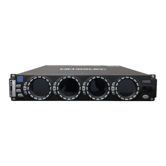
® ® Dolby Lake Processor System Manual Front-Panel Interface Portal Meter Display The Portal provides a revolutionary metering display that allows for multiple channels of metering on a single circular display. The Dolby Lake Processor provides four Portals on the front panel, as shown in Figure 4-3. Figure 4-3 Dolby Lake Processor Front Panel Figure 4-3 shows a variety of Portal output-channel meter views, including four-way, two-way, and three-way crossover modules, and a three-auxiliary-output module. -
Page 29: Figure 4-5 Level Metering In Action
® ® Dolby Lake Processor System Manual Front-Panel Interface Channel Names Each channel represented by the Portal has a user-defined channel name, displayed on either the upper or lower text display depending on the physical location of the meter display. Channel names can be configured using the Dolby Lake Controller software. Channel Identification and Muting The Portal is surrounded by a circle of buttons that provide multiple soft functions. -
Page 30: Meter Modes
® ® Dolby Lake Processor System Manual Front-Panel Interface Multifunction Selection and Communication button on the left side of each Portal provides module selection and muting, menu navigation, and communication indication. button functionality includes: • Temporary display of the frame label on the center line of the selected Portal •... -
Page 31: Menu Mode
® ® Dolby Lake Processor System Manual Front-Panel Interface Figure 4-7 Physical Input Meters Each physical input channel is represented across the Portal displays. Depending upon the input channel configuration, these meters indicate the relevant digital or analog type being used via the Portal text displays. In physical-input channel view, pressing the button allows you to mute Mute Enable... -
Page 32: Main Menu
® ® Dolby Lake Processor System Manual Front-Panel Interface Within this section, Portals are referenced by number, as shown in Figure 4-9. Figure 4-9 Portal Reference Numbers The numbers will be used to help clarify Portal functionality in Menu mode, as detailed in the following sections. -
Page 33: Main Menu Edit Menu Peq Edit
® ® Dolby Lake Processor System Manual Front-Panel Interface The illuminated buttons above and below the text labels on Portals 2 and 3 provide access to PEQ, GEQ, and Levels Edit submenus. Note: The first two default module overlays are used for front-panel editing. If additional overlays are present in the Controller, they are not displayed here. -
Page 34: Figure 4-13 Peq Edit Portal 2
® ® Dolby Lake Processor System Manual Front-Panel Interface Use Up/Down Arrows Select Filter to Edit by Its to Select Next Filter Frequency (Sorted by Freq) Change Filter Type Select Filter Type (ME to Confirm) Select the Bypass/Insert Insert/Bypass Filter Status Figure 4-13 PEQ Edit Portal 2 Portal 3 (and Portal 4 for Mesa filters only) displays the bandwidth, frequency, and... -
Page 35: Main Menu Edit Menu Geq Edit
® ® Dolby Lake Processor System Manual Front-Panel Interface 4.5.4 Main Menu Edit Menu GEQ Edit The Graphic EQ edit menu provides a simplified interface to change the gain of an EQ filter, and to insert or bypass each filter, along with an overlay insert/bypass feature. -
Page 36: Main Menu Edit Menu Levels
® ® Dolby Lake Processor System Manual Front-Panel Interface Portal 3 is used for changing the gain of the selected filter (this portal is blank when the overlay status is selected in Portal 2). +00.01 dB +00.10 dB +01.00 dB +10.00 dB Up/Down Arrow Keys Adjust Gain by 1 dB... -
Page 37: Main Menu Presets Menu
® ® Dolby Lake Processor System Manual Front-Panel Interface • Limiter MaxRMS Level • Limiter MaxRMS Corner • Limiter MaxRMS Attack • Limiter MaxRMS Release • Limiter MaxPeak Level Use the up/down arrows to select the parameter for editing. Portal 4 displays the current value for the selected parameter and allows adjustment of that value using the up/down arrows or the fine adjustment keys where relevant. -
Page 38: Main Menu Utility Menu Reset Processor Menu
® ® Dolby Lake Processor System Manual Front-Panel Interface The Utility menu provides access to two submenus: Reset Processor and Technical Info . Press the corresponding button to access either submenu. Pressing the button returns you to the Main menu. Menu 4.5.8 Main Menu... -
Page 39: Processor Reset Confirmation Display
® ® Dolby Lake Processor System Manual Front-Panel Interface Figure 4-24 Partial Reset Confirmation Menu Figure 4-25 Factory Reset Confirmation Menu For a full factory reset, the module configuration after reset is based on the analog I/O configuration. For example, if you have an LP4D12, the Contour loudspeaker processor configuration is recalled. -
Page 40: Main Menu Utility Menu Technical Information Menu
® ® Dolby Lake Processor System Manual Front-Panel Interface 4.5.11 Main Menu Utility Menu Technical Information Menu The Technical Information menu displays details pertinent to the configuration of the Processor. Portal 1 shows help text to indicate that the up and down arrow keys on the other Portals will toggle through information relevant to each category. -
Page 41: Main Menu Front-Panel Configuration Menu Access Control Menu
® ® Dolby Lake Processor System Manual Front-Panel Interface Portal 2 provides viewing angle control. Adjust this value to provide optimal Portal display performance depending upon the mounting location of the Processor. By default, the Portals display best directly on-axis to the front of the Processor. Adjusting the viewing angle improves display performance when mounting the Processor low to the ground or high in a rack. -
Page 42: Menu Password Entry Keyboard
® ® Dolby Lake Processor System Manual Front-Panel Interface +00.01 EQ Gain Maximum +00.10 +01.00 +10.00 Select Max Limit for Editing Select Min Limit for Editing EQ Gain Minimum Figure 4-30 EQ Limits Portal Portal 3 is intentionally blank. Press on Portal 4 to lock the adjustments made using Portals 1 and 2. -
Page 43: Lake Contour And Mesa Quad Eq Front-Panel Reference
® ® Dolby Lake Processor System Manual Front-Panel Interface Lake Contour and Mesa Quad EQ Front-Panel Reference The Lake Contour and Mesa Quad EQ have a minimal front-panel interface that allows you to recall presets, mute input and output channels, and perform other simple system functions. -
Page 44: Lake Contour Front-Panel Functions
® ® Dolby Lake Processor System Manual Front-Panel Interface 4.6.1 Lake Contour Front-Panel Functions Table 4-1 Lake Contour Front-Panel Functions Function Action Effect in Processor Effect in Controller [Button] Select Processor Press [SEL] No effect. The text on the module icon is highlighted yellow in the work area, and the module scroll bar in the Modules menu locates the... -
Page 45: Mesa Quad Eq Front-Panel Functions
® ® Dolby Lake Processor System Manual Front-Panel Interface 4.6.2 Mesa Quad EQ Front-Panel Functions Table 4-2 Mesa Quad EQ Front-Panel Functions Function Action Effect in Processor Effect in Controller [Button] Select Processor Press No effect. The text on the module icon is highlighted yellow in the work [SEL] area, and the module scroll bar in... - Page 46 Virtual Dolby Technologies Test DVD Track List...
-
Page 47: Chapter 5 Back-Panel Interface
® ® Dolby Lake Processor System Manual Chapter 5 Back-Panel Interface The Dolby Lake Processor back panel provides connections for analog and digital ® ® audio, networking, and more. This chapter provides a detailed description of each connection on the back panel of the Processor. Back-Panel Overview Base Platform Card Slots... -
Page 48: Base Platform
® ® Dolby Lake Processor System Manual Back-Panel Interface Base Platform The base platform is detailed in Figure 5-2. Power Inlet AES/EBU I/O S/PDIF I/O MP I/O Word Clock Memory Slot Ethernet Figure 5-2 Base Platform 5.2.1 Power Inlet The Dolby Lake Processor has an auto-ranging power supply, operating from 100–240 VAC, 50–60 Hz. -
Page 49: Mp I/O
® ® Dolby Lake Processor System Manual Back-Panel Interface Table 5-1 AES/EBU Pin List Signal Description Signal Description Ch 1 & 2 in (+) Ch 1 & 2 in (–) Ch 3 & 4 in (+) Ch 3 & 4 in (–) Ch 5 &... -
Page 50: Memory Slot
® ® Dolby Lake Processor System Manual Back-Panel Interface 5.2.5 Memory Slot A memory slot is provided for storing and recalling presets from a memory card. This feature is currently not supported by the Dolby Lake Processor and will be included in a future software release. -
Page 51: Analog Output Card
® ® Dolby Lake Processor System Manual Back-Panel Interface 5.3.2 Analog Output Card Figure 5-5 Output Card Each output card provides balanced analog audio input connections using male XLR connectors. 5.3.3 Iso-Float Ground Isolation System Analog input and output cards both feature the Iso-Float ground isolation system. -
Page 52: Figure 5-6 Iso-Float Control On Analog Converter Cards
® ® Dolby Lake Processor System Manual Back-Panel Interface Figure 5-6 Iso-Float Control on Analog Converter Cards Iso-Float Operation As shown in the figure above, the Iso-Float two-position switch is labeled GND and Lift/SC . An LED above the switch indicates Iso-Float status. When the switch is in the GND position, all four channels on the converter card will be grounded. -
Page 53: Cobranet Card
® ® Dolby Lake Processor System Manual Back-Panel Interface CobraNet Card Figure 5-7 CobraNet Card CobraNet expansion cards enable CobraNet audio networking between Dolby Lake Processors and other CobraNet devices. The Dolby Lake Processor software supports the following CobraNet functionality: •... -
Page 54: Figure 5-8 Typical Sound System Application
® ® Dolby Lake Processor System Manual Back-Panel Interface CD PLAYER S/PDIF ANALOG ANALOG ANALOG AMPLIFIER I ANALOG MIXING CONSOLE DOLBY LAKE PROCESSOR ANALOG DIGITAL ANALOG AMPLIFIER II DIGITAL WORD CLOCK Figure 5-8 Typical Sound System Application Additionally, Ethernet connections will be made between each Processor. These connections will be performed using physical wire connections, and in many applications, a wireless Ethernet access point will be used to provide a connection to a tablet PC operating the Dolby Lake Controller software. -
Page 55: Chapter 6 Networking
® ® Dolby Lake Processor System Manual Chapter 6 Networking The Dolby Lake Processor must be connected to a network in order to ® ® communicate with the Dolby Lake Controller software. Both wired and wireless network configurations are presented in this chapter. Additionally, networking configurations containing Processors and Lake Contour and Mesa Quad EQ processors are presented. -
Page 56: Connecting Multiple Processors On Wired Ethernet Networks
® ® Dolby Lake Processor System Manual Networking Table 6-1 Common Ethernet Cable Categories Category Spectral B/W Length Cat3 16 MHz 100 m 10Base-T Cat4 20 MHz 100 m 16 Mbps Cat5e 100 MHz 100 m 100Base-T Cat6 250 MHz 100 m Emerging Cat5e cabling meets the requirements for the Dolby Lake Processor Ethernet network,... -
Page 57: Wireless Network Operation
® ® Dolby Lake Processor System Manual Networking Figure 6-2 Complex Network Connection Gateways to other Ethernet transport layers, such as fiber optics, can also be incorporated into the system. Wireless Network Operation Adding wireless networking to the system provides portable centralized control to a distributed network of processors. -
Page 58: Networking With Lake Contour And Mesa Quad Eq Processors
® ® Dolby Lake Processor System Manual Networking Networking with Lake Contour and Mesa Quad EQ Processors Lake Contour and Mesa Quad EQ processors both utilize 10Base-T, a 10 MHz Ethernet network. Since these processors have a lower-bandwidth network connection, care should be taken when connecting these processors to a network containing Dolby Lake Processors that utilize 100Base-T, a 100 MHz Ethernet network. -
Page 59: Chapter 7 Connecting Digital Audio Devices
® ® Dolby Lake Processor System Manual Chapter 7 Connecting Digital Audio Devices Connecting multiple digital audio devices has always been a complex subject. With the variety of sample rates commonly utilized for various transport protocols and storage media, the practitioner must juggle multiple differing requirements. Additionally, the demands of live sound and multimedia studio production may require mix stems at multiple sample rates for multiple destinations. -
Page 60: Figure 7-1 Dolby Lake Processor Clock System
® ® Dolby Lake Processor System Manual Connecting Digital Audio Devices 192 kHz sample rates. The user can configure the Processor to provide a different sample rate for each stereo digital channel. Figure 7-1 shows a simplified block diagram of the Processor clock system. INPUTS OUTPUTS INTERNAL... -
Page 61: Clock Source Priorities
® ® Dolby Lake Processor System Manual Connecting Digital Audio Devices Both Primary and Sample Rate Converter clocks produce multiple audio clocks derived from a base sample rate. The Primary Clock’s base rate is 48 kHz, which also derives the 96 and 192 kHz clocks. The Sample Rate Converter Clock’s base rate can either be 44.1 or 48 kHz. -
Page 62: Cascading Aes And Word Clock Input Signals
® ® Dolby Lake Processor System Manual Connecting Digital Audio Devices each clock (either 44.1 or 48 kHz). This will ensure that digital I/O continues at the expected clock sample rate. Cascading AES and Word Clock Input Signals Cascading AES and word clock input signals are additional features of the Dolby Lake Processor. -
Page 63: Signal Processing Latency
® ® Dolby Lake Processor System Manual Connecting Digital Audio Devices Figure 7-4 Cascading Word Clock Connection When using this feature, ensure that the last processor in the word clock chain provides 75Ω termination. Signal Processing Latency The Dolby Lake Processor provides a drastic reduction in latency as compared to other available solutions. -
Page 64: Figure 7-5 Dolby Lake Processor Latencies
® ® Dolby Lake Processor System Manual Connecting Digital Audio Devices INPUTS OUTPUTS Analog: Analog: 24-bit 96 kHz A/D 24-bit 96 kHz D/A 0.072 ms 0.252 ms Digital Asynchronous: Digital Asynchronous: 44.1 kHz 44.1 kHz 0.267 ms 0.241 ms 48 kHz 48 kHz 0.263 ms 0.237 ms... -
Page 65: Table 7-1 Common Input-Output Latencies
® ® Dolby Lake Processor System Manual Connecting Digital Audio Devices Table 7-1 Common Input-Output Latencies Common Input-Output Latencies Input Input Processing Output Output Total Configuration Latency Latency Configuration Latency Latency Analog 0.072 ms 0.781 ms Analog 0.252 ms 1.105 ms 48 kHz sync 0.26 ms 0.781 ms... - Page 66 Virtual Dolby Technologies Test DVD Track List...
-
Page 67: Index
® ® Dolby Lake Processor System Manual Index access control menu reference front panel configuration menu AES/EBU I/O front-panel functions ambient light sensor Lake Contour analog I/O 40–41 Mesa Quad EQ analog input card GEQ edit menu analog output card ground isolation system back-panel interface 37–45... - Page 68 ® ® Dolby Lake Processor System Manual Connecting Digital Audio Devices networking 47–51 A/D inputs features audio performance\t Lake Contour and Mesa Quad EQ back panel interface multiple processors cable wireless combined A/D and D/A password entry keyboard D/A outputs PEQ edit menu sample rate converters \t Portal...
Need help?
Do you have a question about the Lake LPD and is the answer not in the manual?
Questions and answers