
Related Manuals for TUG Technologies 660

Summary of Contents for TUG Technologies 660
- Page 1 MOBILE BELT LOADER MODEL 660 & 663 OPERATION MANUAL Volume 1 of 1 Originally Issued December 2015 CD397-Oper...
-
Page 2: Copyright Notice
COPYRIGHT NOTICE © This manual is copyright 2015 Tug Technologies Corporation (TUG). All rights reserved. This manual contains confidential and proprietary information. This document and any information contained herein, may not be reproduced or redistributed in any form whatsoever without the express, written consent of TUG. -
Page 3: Record Of Revisions
Introduction Mobile Belt Loader Model 660 Operation Manual RECORD OF REVISIONS Property of: _____________________________________________________________________ Company: _____________________________________________________________________ Address: _____________________________________________________________________ City: _______________________________ State/Province: _____________________ Country: _______________________________ Zip/Postal Code: _____________________ REVISION DATA Check each revision received, and insert the revised and supplementary pages in your manual.Tug Technologies Corporation assumes no liability for personal injury or equipment failure due to any oper- ation performed without heed to manual revisions. - Page 4 Mobile Belt Loader Model 660 Introduction Operation Manual LIST OF EFFECTIVE PAGES Only pages that have been revised are listed in Table Introduction - 1 - 2: List of Effective Pages. Table Introduction - 1 - 2: List of Effective Pages Page Revision Date Page Revision Date CD397-Oper Introduction - 1 - iv...
-
Page 5: Table Of Contents
Warranty Cancellation.................Introduction - 1 - 5 Warranty Exclusions .................Introduction - 1 - 5 Warranty Claim Process ................Introduction - 1 - 6 Contact TUG Technologies..............Introduction - 1 - 6 Parts....................Introduction - 1 - 7 Return Parts ..................Introduction - 1 - 7 Labor ....................Introduction - 1 - 7... - Page 6 Mobile Belt Loader Model 660 Introduction Operation Manual 2.1.1 Ramp Safety in Aircraft Handling............Safety - 2 - 13 2.2 General Ramp Safety ..................Safety - 2 - 13 2.2.1 Danger Areas..................Safety - 2 - 13 2.2.2 Engine Intake Area ................Safety - 2 - 14 2.2.3 Equipment Restraint Area &...
- Page 7 2.6 Locations of Technical Construction Files ..........Operation - 2 - 25 Section 3: Specifications ................Operation - 3 - 27 3.1 General Specifications of the 660 ..............Operation - 3 - 27 3.1.1 Dimensions ..................Operation - 3 - 27 3.2 Torque Values....................Operation - 3 - 28 3.2.1 Metric Fasteners ................Operation - 3 - 28...
- Page 8 Mobile Belt Loader Model 660 Introduction Operation Manual 3.11.5.2 Deutz 2.9L................Operation - 3 - 45 3.11.6 Emergency Stop Switch..............Operation - 3 - 45 3.11.7 Park Brake ..................Operation - 3 - 45 3.11.8 Pilot-Operated Hydraulic Check Valves ..........Operation - 3 - 45 3.11.9 Safety Props ...................Operation - 3 - 46...
- Page 9 Introduction Mobile Belt Loader Model 660 Operation Manual 5.3.3 Tires ....................Operation - 5 - 54 5.3.4 Lubrication ..................Operation - 5 - 54 5.3.5 Fluid Levels..................Operation - 5 - 54 5.3.6 Battery....................Operation - 5 - 54 5.3.7 Diesel Engine..................Operation - 5 - 55 5.3.7.1 Deutz 2.9L Engine ..............Operation - 5 - 55...
- Page 10 Mobile Belt Loader Model 660 Introduction Operation Manual THIS PAGE INTENTIONALLY BLANK Introduction - 1 - x CD397-Oper...
-
Page 11: List Of Figures
Introduction Mobile Belt Loader Model 660 Operation Manual LIST OF FIGURES Figure Introduction - 1 - 1 - TUG Identification Plate .........Introduction-1-1 Figure Introduction - 1 - 2 - Model Numbers ............Introduction-1-2 Figure Safety - 2 - 1 - Idle Power - Engine Intake Area NO Zone......Safety-2-15 Figure Safety - 2 - 2 - Breakaway Power - Engine Blast Area NO Zone .... - Page 12 Mobile Belt Loader Model 660 Introduction Operation Manual THIS PAGE INTENTIONALLY BLANK Introduction-1-xii CD397-Oper...
-
Page 13: List Of Tables
Introduction Mobile Belt Loader Model 660 Operation Manual LIST OF TABLES Table Introduction - 1 - 1: Revisions ..............Introduction-1-iii Table Introduction - 1 - 2: List of Effective Pages ..........Introduction-1-iv Table Introduction-1-1: Service Recalls/Notification ...........Introduction-1-4 Table Introduction-1-2: Flat Rate Labor Guide ..........Introduction-1-10 Table Safety-1-1: Standard Safety Equipment ............ - Page 14 Mobile Belt Loader Model 660 Introduction Operation Manual THIS PAGE INTENTIONALLY BLANK Introduction-1-xiv CD397-Oper...
-
Page 15: Unit Identification
The information and instructions in this manual are intended to acquaint the operator with the important operating features of the TUG Mobile Belt Loader Model 660. The various controls, gauges, switches, and operating features are explained and illustrated throughout this manual. -
Page 16: Model Number
Conveyor Variations Engine Variations Engine Variations 660 = 34 in Wide x 24 ft Long 660 = 34 in Wide x 24 ft Long 28 = Ford MSG-425 (2.5 L) 4 Cylinder Gasoline/LP 28 = Ford MSG-425 (2.5 L) 4 Cylinder Gasoline/LP 663 = 31.5 in. -
Page 17: Warranty Information
- all aspects of the products themselves and the service that backs them up. This manual is directed to TUG Technologies’ distributors and customers of TUG Equipment. It should be used to implement the Warranty Program at every level. -
Page 18: Warranty
WARRANTY A warranty is a specific document that guarantees the quality of goods to a purchaser within a specified length of time and according to usage limitations. The TUG Technologies warranty statement defines the conditions of the warranty. A warranty: 1. -
Page 19: Warranty Cancellation
Damaged due to accidents. • Damage due to abuse, improper operation or poor maintenance practices. Total or partial warranty cancellation is registered in TUG Technologies’ records. WARRANTY EXCLUSIONS The following items are examples of some of the non-reimbursable items under the Warranty and Policy Program. -
Page 20: Warranty Claim Process
Towing expense or transportation for moving equipment between the customer's location and the repair location. WARRANTY CLAIM PROCESS No warranty invoice will be accepted unless TUG Technologies has been con- NOTE: tacted prior to the start of work being done to the unit. -
Page 21: Parts
Return Parts Not all failed parts need to be returned to TUG Technologies. If parts are to be returned, an RGA tag will be sent with the replacement warranty parts. The tag must be filled out completely and attached to the return part(s). -
Page 22: Aircraft Ground Support Equipment
All the expenses related to a warranty claim will be invoiced to the buyer until TUG Technologies has evaluated the claim. Whatever the circumstances, the buyer should not refuse or delay the payment. - Page 23 The warranty is automatically void by TUG Technologies in the following cases: 1. The product has received some modification not authorized or completed according to TUG Technologies requirements. 2. Some original parts have been replaced by parts not provided by TUG Technologies. CD397-Oper Introduction - 1 - 9...
-
Page 24: Warranty Labor Flat Rate Guide
Mobile Belt Loader Model 660 Introduction Operation Manual WARRANTY LABOR FLAT RATE GUIDE Table Introduction-1-2, “Flat Rate Labor Guide,” lists the labor rates for various task. Table Introduction-1-2: Flat Rate Labor Guide Part Hours R&R Cooling System Radiator, Transfer Shroud Top or Bottom Hose Heater Hose Water Pump Thermostat R&R Controls Shifter Shifter Cable &... - Page 25 Introduction Mobile Belt Loader Model 660 Operation Manual Table Introduction-1-2: Flat Rate Labor Guide (Continued) Part Hours Body Repaint Repaint Cab R&R Brakes Master Cylinder & Bleed Brake Booster Adjust Brake Booster Hard Brake Lines & Bleed Master Cylinder Cover Gasket Brake Pedal Brake Return Spring Hub Front...
- Page 26 Mobile Belt Loader Model 660 Introduction Operation Manual Table Introduction-1-2: Flat Rate Labor Guide (Continued) Part Hours Hour Meter Ammeter Electric Fuel Gauge Electric Fuel Sender Kysor Coolant Temp Sensor Kysor Oil Pressure Sensor Kysor Override Switch Light Switch Battery Cable Wire Harness Kysor Warning Light...
- Page 27 Introduction Mobile Belt Loader Model 660 Operation Manual Table Introduction-1-2: Flat Rate Labor Guide (Continued) Part Hours Spark Plug Wires Engine Assembly Oil Pan Front Crankshaft Seal R&R Exhaust Exhaust Pipe Muffler Tail Pipe R&R Front Suspension & Steering Front Spring Front Axle and Transfer Springs Tie Rod End & Adjust Toe In...
- Page 28 Mobile Belt Loader Model 660 Introduction Operation Manual Table Introduction-1-2: Flat Rate Labor Guide (Continued) Part Hours R&R Fuel System Fuel Cell Fuel Line Steel LP Lock Off Valve LP Regulator Miscellaneous Install Rubber Bumper R&R Hood Latch Install Decal R&R Seating Seat Frame Bucket Seat R&R Transmission Transmission Transmission Front Oil Seal - Gas...
- Page 29 Introduction Mobile Belt Loader Model 660 Operation Manual Table Introduction-1-2: Flat Rate Labor Guide (Continued) Part Hours Conveyor Kill Switch Conveyor Kill Switch Wiring Harness Electric Eyes Glow Plug Relay R&R Hydraulics Hydraulic Pump Hydraulic Pump Pulley Main Manifold Steering, Brakes Relief, & Adjustment Valve 2-Lever Valve Under Seat...
- Page 30 Mobile Belt Loader Model 660 Introduction Operation Manual Table Introduction-1-2: Flat Rate Labor Guide (Continued) Part Hours Hydraulic Tank Drain and Refill Hydraulic Tank R&R Conveyor Conveyor Belt Front Drive Roller (Includes Belt) Front Drive Roller Bearing (Includes Belt) Front Drive Roller Sprocket Rear Idler Roller (Includes Belt)
-
Page 31: Technical Assistance
Introduction Mobile Belt Loader Model 660 Operation Manual TECHNICAL ASSISTANCE Direct any questions concerning the operation of the 660 Mobile Belt Loader to: TUG Technologies Corporation 1995 Duncan Dr. Kennesaw, GA 30144 Email: info@tugtech.com Direct any questions concerning parts for the 660 Mobile Belt Loader to:... - Page 32 Mobile Belt Loader Model 660 Operation Manual THIS PAGE INTENTIONALLY BLANK Introduction - 1 - 18 CD397-Oper...
-
Page 33: How To Use This Manual
Introduction Mobile Belt Loader Model 660 Operation Manual HOW TO USE THIS MANUAL Important Notice: TUG recommends that the vehicle operator thoroughly study the NOTE: contents of this manual before attempting to operate the vehicle. This manual contains an introduction, safety information, and one chapter. Refer to the Table of Contents at the front of this manual and in the chapter for details of content. - Page 34 Mobile Belt Loader Model 660 Introduction Operation Manual THIS PAGE INTENTIONALLY BLANK Introduction - 1 - 20 CD397-Oper...
-
Page 35: Safety
Safety Mobile Belt Loader Model 660 Operation Manual Safety Section 1: General Safety Guidelines 1.1 Introduction Operator and mechanic safety is important at TUG. During the design and production of every product, a thorough safety review of all components is standard operating procedure. As a result of this review, safety warnings, cautions, and notes are provided throughout this manual. - Page 36 Mobile Belt Loader Model 660 Safety Operation Manual Table Safety-1-1: Standard Safety Equipment (Continued) Equipment Turn signals with Hazard Warnings Dual independent brake systems with brake warning light Power-boosted front disc brakes and rear drum brakes Adjustable over-center park brake hand lever Lighted transmission shift control...
-
Page 37: Optional Safety Features
Safety Mobile Belt Loader Model 660 Operation Manual Table Safety-1-1: Standard Safety Equipment (Continued) Equipment Independent expanding shoe and drum park brake on transmission output shaft or in rear axle Non slip covering on floor board Non slip surface on brake and accelerator pedal High coolant temperature/low oil pressure shutdown (Ford 2.5L only) (optional on other engines) 1.3 Optional Safety Features... -
Page 38: Safety Responsibilities
Mobile Belt Loader Model 660 Safety Operation Manual 1.4 Safety Responsibilities General rules cannot be written to cover every possible situation that may arise with each job function, task, or procedure. Therefore, certain definite responsibilities rest with the individual. These responsibilities include: •... -
Page 39: Operator Safety Responsibility
Safety Mobile Belt Loader Model 660 Operation Manual 1.5 Operator Safety Responsibility WARNING: DO NOT DRIVE A BELT LOADER WITH DEFECTIVE BRAKES, STEERING, TIRES, HORN, PARKING BRAKE, CONVEYOR BELT, OR LIGHTS. COMMUNICATE THESE PROBLEMS TO YOUR SUPERVISOR. Follow station safety rules. If you do not have a written list of safety rules, ask for one NOTE: prior to operating this belt loader. - Page 40 Mobile Belt Loader Model 660 Safety Operation Manual Table Safety-1-3: Operator Safety Responsibilities (Continued) Operator Responsibility Do not allow the belt loader to be pushed by other equipment or use the belt loader to push other equipment. Use proper towing equipment. Do not tamper with engine.
-
Page 41: Mechanic Safety Responsibility
Safety Mobile Belt Loader Model 660 Operation Manual 1.6 Mechanic Safety Responsibility WARNING: ALWAYS USE THE SAFETY PROPS WHEN WORKING UNDER THE CONVEYOR. Table Safety-1-4: Mechanic Safety Mechanic Safety Keep hands and clothing away from rotating parts Wear secured clothing Use the conveyor safety prop whenever working under conveyor Allow engine to cool before adjusting the alternator belt or hydraulic pump belt Keep hands. -
Page 42: Emergency Procedures
DEATH, SERIOUS INJURY, OR PROPERTY DAMAGE. 1.7.1 Disabled or Stalled Vehicle The Model 660 is equipped with an emergency hydraulic pump activated from the operator’s sta- tion actuated b y a spring-loaded two-position switch. This e m e r g e n c y pump supplies hydraulic pressure for the service brake and steering. -
Page 43: Operational Engine - Unable To Move
Safety Mobile Belt Loader Model 660 Operation Manual 2. Turn on the emergency hazard warning signals. CAUTION: Turn on headlights when/if visibility is limited. 3. If unable to move the tow tractor out of the traffic area and when visibility is limited, set out one type of emergency warning device (i.e. -
Page 44: Inoperable Engine With Electrical Power
Mobile Belt Loader Model 660 Safety Operation Manual 1.7.1.3 Inoperable Engine With Electrical Power When the engine is inoperable it will experience loss of power. 1. Release the park brake. CAUTION: Engaging the emergency hydraulic pump for more than one min- ute will cause the electric motor to overheat. If emergency procedures can- not be completed within one minute, disengage and allow the pump to cool for at least 10 minutes before re-engaging. -
Page 45: Recommended Fire Procedure
Safety Mobile Belt Loader Model 660 Operation Manual 3. Tow unit. 4. Once towing destination is reached, place transmission of the towing vehicle in neutral, apply the park brake and turn the ignition key to the OFF position. 5. Chock wheels of the disabled unit. -
Page 46: Collisions
Mobile Belt Loader Model 660 Safety Operation Manual 1.7.3 Collisions WARNING: IN A COLLISION, INJURIES, POSSIBLE FUEL LEAKS, OR DAM- AGE TO THE VEHICLE CAN OCCUR. Every operator must take precautions to prevent collisions. If a collision occurs, remain calm and perform the following steps: 1. -
Page 47: Section 2: Iata Flightline Safety Guidelines
Safety Mobile Belt Loader Model 660 Operation Manual Section 2: IATA Flightline Safety Guidelines 2.1 IGOM Chapter 4: Aircraft Handling Procedures This section of the TUG Operators Manual has been created from the IATA ground Operations Manual (IGOM). This section provides general guidelines for GSE handling, including safety pro- cedures. The ground support equipment operator must always follow the training and equipment operating rules of their employer. -
Page 48: Engine Intake Area
Mobile Belt Loader Model 660 Safety Operation Manual 2.2.2 Engine Intake Area Make sure the engine intake area is clear: • At arrival, until the engines have been switched off and are spooling down • At departure or just before pushback • At all times while engines are running. -
Page 49: Figure Safety - 2 - 1: Idle Power - Engine Intake Area No Zone
Safety Mobile Belt Loader Model 660 Operation Manual 10 ft. (3m) 3.75 ft. (1m) 250 ft. (75m) 30° Figure Safety - 2 - 1: Idle Power - Engine Intake Area NO Zone CD397-Oper Safety - 2 - 15... -
Page 50: Figure Safety - 2 - 2: Breakaway Power - Engine Blast Area No Zone
Mobile Belt Loader Model 660 Safety Operation Manual 25 ft. (8m) 8 ft. (2.4m) 500 ft. (150m) 30° Figure Safety - 2 - 2: Breakaway Power - Engine Blast Area NO Zone Safety - 2 - 16 CD397-Oper... -
Page 51: Equipment Restraint Area & Equipment Restraint Line
Safety Mobile Belt Loader Model 660 Operation Manual 2.2.3 Equipment Restraint Area & Equipment Restraint Line The Equipment Restraint Area (ERA) is defined as the area of the apron bordered by a red line known as the Equipment Restraint Line, or otherwise indicated, in which an aircraft is parked during ground operations. -
Page 52: Fod Checks
Mobile Belt Loader Model 660 Safety Operation Manual Every individual has a responsibility to ensure that the risk of damage to aircraft from FOD is min- imized. All FOD must be removed and properly disposed when found. Table Safety-2-1: Examples of FOD Example Metal nuts and bolts... -
Page 53: Safety Instructions For Operating Motorized Vehicles On Ramp
Safety Mobile Belt Loader Model 660 Operation Manual Table Safety-2-2: FOD Checks (Continued) Checks Pick up and dispose all FOD in designated garbage bins 2.3 Safety Instructions for Operating Motorized Vehicles on Ramp 2.3.1 General Safety Instructions for Ground Support Equipment (GSE) Follow these procedures when operating GSE on ramp: CAUTION: Only trained and authorized personnel are allowed to drive or operate specific GSE. -
Page 54: Belt Loader Aircraft Loading Equipment
Mobile Belt Loader Model 660 Safety Operation Manual • Do not leave any vehicle unattended with its engine running. • Do not drive GSE with lifting devices in the raised position, except for final positioning of the GSE onto the aircraft. -
Page 55: Ground Support Equipment Safety Driving And Parking Inside Era
Safety Mobile Belt Loader Model 660 Operation Manual 2.3.4 Ground Support Equipment Safety Driving and Parking Inside ERA Apply the following precautions when driving or parking Ground Support Equipment (GSE) within the ERA: • Make a minimum of one complete stop with all motorized vehicles/equipment prior to entering the ERA. -
Page 56: Thunderstorms
2.5 ISO 7000 and 7010 Safety Guidelines 2.5.1 International Decals and Symbols. TUG Technologies produces Aerospace Ground Support Equipment used all over the world. Operator safety makes it imperative to avoid language barriers caused by decals written in West- ern-style English. International Standards ISO 7000 and ISO 7010 (Registered Safety Signs) are becoming accepted for universal, non-verbal communication. - Page 57 TUG Technologies equipment. TUG Technologies strongly suggests using this information as training material for operators of TUG equipment. Since ISO 7000 and 7010 are under constant revision, TUG Technologies will maintain this page, keeping TUG Technologies manuals current as ISO 7000 and ISO 7010 evolve.
-
Page 58: Figure Safety - 2 - 4: Fasten Seat Belts (White On Blue Background)
Mobile Belt Loader Model 660 Safety Operation Manual T-B7 Figure Safety - 2 - 4: Fasten Seat Belts (White on Blue Background) T-B8 Figure Safety - 2 - 5: Use Hearing Protection (White on Blue Background) Safety - 2 - 24 CD397-Oper... -
Page 59: Material Data Safety Sheet Information
Safety Mobile Belt Loader Model 660 Operation Manual TY-64 Figure Safety - 2 - 6: Hot Surface (Yellow Field with Black Border) MATERIAL DATA SAFETY SHEET INFORMATION A Material Safety Data Sheet (MSDS) is a written document that outlines information and proce- dures for handling and working with chemicals MSDS documents contain • physical and chemical property information, •... -
Page 60: Links For Products
Mobile Belt Loader Model 660 Safety Operation Manual • what to expect when the safety recommendations are not followed. • In addition, it explains what to do when accidents occur and how to recognize symptoms of overexposure. The MSDS listed within this Service manual apply to all models of the belt loader, it is recom- mended they be communicated to your company’s Health &... - Page 61 Safety Mobile Belt Loader Model 660 Operation Manual http://msdspds.castrol.com/msdspds/msdspds.nsf/CastrolResults?Open- Form&c=USA%20(US)&l=English%20(US)&p=&n=459027&b=All&t=MSDS&autosearch=N o&autoload=No&sitelang=EN&output=Full&spu=Lubricants&unrestrictedmb=No&cols=0 MSDS for NAPA DOT 3 Brake Fluid http://s7d9.scene7.com/is/content/GenuinePartsCompany/715873pdf?$PDF$ MSDS for CHEVRON Supreme Prediluted 550/50 Antifreeze Coolant (Contains Bitterant) https://cglapps.chevron.com/msdspds/MSDSDetailPage.aspx?docDataId=34258&docFor- mat=PDF MSDS for Castrol Pyroplex Red EP 2 http://msdspds.castrol.com/msdspds/msdspds.nsf/CastrolResults?Open- Form&c=USA%20(US)&l=English%20(US)&p=&n=464255&b=All&t=MSDS&autosearch=N o&autoload=No&sitelang=EN&output=Full&spu=Lubricants&unrestrictedmb=No&cols=0...
- Page 62 Mobile Belt Loader Model 660 Safety Operation Manual THIS PAGE INTENTIONALLY BLANK Safety - 2 - 28 CD397-Oper...
-
Page 63: Operation
2.5 ISO Product Safety Evaluation ..............Operation-2-25 2.6 Locations of Technical Construction Files ............ Operation-2-25 Section 3: Specifications ................Operation-3-27 3.1 General Specifications of the 660 ..............Operation-3-28 3.1.1 Dimensions ..................Operation-3-28 3.2 Torque Values....................Operation-3-28 3.2.1 Metric Fasteners .................. Operation-3-29 3.2.2 Graded Bolts .................. - Page 64 Mobile Belt Loader Model 660 Operation Operation Manual 3.4.2 Diesel ....................Operation-3-36 3.5 Transmission....................Operation-3-37 3.5.1 Gear Ratios..................Operation-3-37 3.6 Standard Conveyor Heights and Angles............Operation-3-38 3.7 Compatible Aircraft ..................Operation-3-39 3.8 Fluids ......................Operation-3-43 3.9 Coolant......................Operation-3-44 3.10 Recommended Spare Parts................ Operation-3-44 3.11 Safety Features...................
- Page 65 Operation Mobile Belt Loader Model 660 Operation Manual 5.3.10 Exhaust ....................Operation-5-58 5.3.11 Tires ....................Operation-5-58 5.3.12 Lubrication ..................Operation-5-58 5.3.13 Levels....................Operation-5-58 5.3.14 Wheel Bearings.................. Operation-5-58 5.3.15 Battery....................Operation-5-58 5.3.16 Fuel System ..................Operation-5-59 5.3.17 Engine Exterior .................. Operation-5-59 5.3.18 Tagging ....................
-
Page 66: Section 1: System Overview
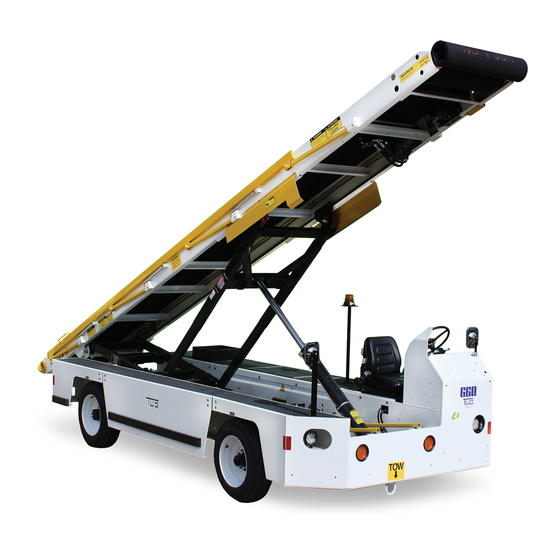
Safety section. The TUG Mobile Belt Loader Model 660 is a self-propelled vehicle designed to load and unload baggage, light freight, and mail into and out of the lower hold of aircraft. The conveyor may also be used to transfer freight from trucks or between any two points at the same or differing eleva- tions. -
Page 67: Diesel - Deutz 2.9L
1.4.8 Chassis The 660 Mobile Belt Loader is built on a heavy duty chassis which includes the power package and running gear. The chassis has a 110 in. (279.4 cm) wheel base, formed steel channel frame supported by the front and rear axles. -
Page 68: Conveyor
Model 660. The conveyor frame is 34 in. (86.36 cm) wide on 660 and 31.5 in. (80.009 cm) on 663. The con- veyor belt is 24 in. (60.96 cm) wide on all models and is supported by 2 in. (5.08 cm) diameter rollers and is hydraulic motor-driven through a roller chain reduction. -
Page 69: Electrical System
Operation Mobile Belt Loader Model 660 Operation Manual Engine controls are mounted in the operator’s compartment instrument panel and include hour meter, ignition switch, and light switches. 1.4.12 Electrical System Electrical power is supplied by an alternator, belt-driven, mounted on the side of the engine. The system is a 12-volt, direct current system with negative ground. -
Page 70: Lift Cylinders And Conveyor Motor
Mobile Belt Loader Model 660 Operation Operation Manual line that returns oil to the hydraulic oil reservoir through ports on the valve manifold assembly. When the brake pedal is released, pressure is reduced and the spring loaded check valve opens, allowing hydraulic fluid to return to the hydraulic oil reservoir through ports on the valve manifold assembly and the return line hydraulic filter. - Page 71 The 660 belt loader is equipped with an electrically operated emergency hydraulic pump to allow short term operation of the hydraulic system for raising or lowering the conveyor, in the event of an engine failure.
- Page 72 Mobile Belt Loader Model 660 Operation Operation Manual THIS PAGE INTENTIONALLY BLANK Operation - 1 - 10 CD397-Oper...
-
Page 73: Section 2: Operational Procedures
“Figure Operation - 2 - 2” lists the controls, indicators, and equipment found on the instrument panel for the 660 Belt loader with the Deutz Tier 4F engine, and explains the specific function of each. Reference Table Operation-2-2, “Instrument Panel Description - Deutz 2.9L,” for a descrip- tion of the items shown. - Page 74 Mobile Belt Loader Model 660 Operation Operation Manual Figure Operation - 2 - 1 Instrument Panel - Ford 2.5L Table Operation-2-1 Instrument Panel Description - Ford 2.5L Name Description Ignition Switch Turn this switch to start or turn off the engine. Warning Light (Green) This light will not illuminate if an e-stop on the vehi- cle is activated.
- Page 75 Operation Mobile Belt Loader Model 660 Operation Manual Table Operation-2-1 Instrument Panel Description - Ford 2.5L (Continued) Name Description Conveyor Hand Throttle This knob controls the engine speed only while the unit is in neutral and the parking brake is applied. Turn the knob counterclockwise and the engine will speed up.
-
Page 76: Figure Operation - 2 - 2 Instrument Panel - Deutz 2.9L
Mobile Belt Loader Model 660 Operation Operation Manual Figure Operation - 2 - 2 Instrument Panel - Deutz 2.9L Table Operation-2-2 Instrument Panel Description - Deutz 2.9L Name Description Shifter This is the main drive control for forward or reverse direction. The shifter is labeled: F=Foward, R=Reverse, and N=Neutral. Converter Speed Control These buttons control the engine speed only while the belt loader is in neutral and the parking brake is applied. -
Page 77: Maneuvering Controls
Operation Mobile Belt Loader Model 660 Operation Manual Table Operation-2-2 Instrument Panel Description - Deutz 2.9L (Continued) Name Description Deutz Cold Start Wait Light When the ignition switch is turned on, this light illuminates. When the light goes out, it shows that the glow plugs are heated and the vehicle can be started. -
Page 78: Conveyor Controls
Mobile Belt Loader Model 660 Operation Operation Manual Steering Shifter Wheel Turn Signal Parking Brake T-B7 Foot Throttle Brake Pedal Front Cylinder Control Rear Cylinder Control Figure Operation - 2 - 3 Maneuvering and Conveyor Controls 2.1.4 Conveyor Controls Conveyor height controls in the operator’s compartment (located below driver’s seat) are limited 1. -
Page 79: Electrical Supply
Operation Mobile Belt Loader Model 660 Operation Manual Electrical belt drive controls may be located at any combination of the conveyor's four corners. On the Ford 2.5L, the conveyor hand throttle controls engine speed while in neutral. Turn the knob counterclockwise and the engine will speed up. Depress the hand throttle knob and the engine will return to idle. -
Page 80: Maneuvering Procedures
Mobile Belt Loader Model 660 Operation Operation Manual 1. Fuel Level 2. Tire Inflation 3. Engine Oil Level 4. Transmission Oil Level 5. Seatbelt Serviceability 6. Service Brake Effectiveness 7. Parking Brake Effectiveness 8. Vehicle Drive Forward 9. Vehicle Drive Reverse 10. -
Page 81: Engine Start (Diesel)
Operation Mobile Belt Loader Model 660 Operation Manual 3. Move ignition switch to “Start”. 4. Allow ignition switch to return to “On” upon engine start. NOTE: Switch must be returned to “Off” (reset) before it can be moved to start again. -
Page 82: Depress Foot Throttle
Mobile Belt Loader Model 660 Operation Operation Manual 4. Select transmission drive (FWD/REV) To select a vehicle drive direction in a CE configured belt loader: 1. Move transmission drive selector lever up (toward instrument panel) to select forward drive direction. -
Page 83: Maneuvering The Baggage Loader Around The Aircraft
Operation Mobile Belt Loader Model 660 Operation Manual 2.1.7.7 Maneuvering the baggage loader around the aircraft 1. Approach the aircraft to a distance of two or three feet. 2. Move transmission selector to Neutral. 3. Apply parking brake. 4. Raise the front and rear of the conveyor to the correct heights for the aircraft. - Page 84 Mobile Belt Loader Model 660 Operation Operation Manual CAUTION: Do not tow the Belt Loader unless absolutely necessary. CAUTION: Do not allow the Belt Loader to be pushed by other equipment. CAUTION: Verify the steering system operates properly. The steering wheel should turn the front wheels of the vehicle.
-
Page 85: Conveyor Safety Props
Operation Mobile Belt Loader Model 660 Operation Manual 2.1.9 Conveyor Safety Props WARNING: ALWAYS USE THE SAFETY PROPS WHEN WORKING UNDER THE CONVEYOR. Rear Safety Props Front Safety Props Figure Operation - 2 - 5 Belt Loader with Props Engaged 1. The safety props are provided to support the front and rear of the conveyor for mainte- nance, checking oil, etc. -
Page 86: Iata
Mobile Belt Loader Model 660 Operation Operation Manual • Slowly let the conveyor down until the safety prop aligns with sockets on bottom of the lift arm. CAUTION: Make sure the safety prop is fully engaged inside sockets before working under the conveyor. -
Page 87: Iso Product Safety Evaluation
2.6 Locations of Technical Construction Files The Technical Construction Files are in two places: 1. F2 Labs, Ohio, USA (CE Certifying Body) 2. TUG Technologies Corporation, Kennesaw, GA, USA The Technical File at TUG will be made available at our premises if requested. CD397-Oper Operation - 2 - 25... - Page 88 Mobile Belt Loader Model 660 Operation Operation Manual THIS PAGE INTENTIONALLY BLANK Operation - 2 - 26 CD397-Oper...
-
Page 89: Section 3: Specifications
Operation Mobile Belt Loader Model 660 Operation Manual Section 3: Specifications This section contains information about the specifications for the Mobile Belt Loader Model 660. 3.1 General Specifications of the 660 3.1.1 Dimensions Table Operation-3-1: Dimensions and Measurements Dimension Measurement Length 300 in (762 cm) Width (excluding side bumpers) 78 in (198.1 cm) Height 59 in (149.9 cm) -
Page 90: Torque Values
The following torque tables apply to graded metric and standard fasteners used on the Model 660. The listed values apply to bolts threaded into either nuts or tapped holes in iron or steel. These torque values are not a replacement for torque values specified elsewhere in this manual. -
Page 91: Graded Bolts
Operation Mobile Belt Loader Model 660 Operation Manual Table Operation-3-2: Torque Values for Metric Fasteners (Continued) Nominal Pitch Class 8.8 Class 10.9 Class 12.9 Diameter (mm) (Nm) (Nm) (Nm) (mm) 916.533 1312.432 1533.430 1243.285 1778.833 2079.825 1692.060 2421.491 2829.592 2173.376 3110.246 3634.948 The listed torque values are based on the use of zinc plated, dry threads (or as NOTE: received for the 12.9). - Page 92 Mobile Belt Loader Model 660 Operation Operation Manual Table Operation-3-3: Torque Values for Graded Bolts (Continued) Nominal Threads SAE J429 Grade 5 SAE J429 Grade 8 Diameter (in.) per Inch (ft-lbs) (ft-lbs) 7/16 9/16 1 1/4 1055 1710 1 1/2 1865 3024 NOTE: The listed torque values are based on the use of zinc plated, dry threads.
-
Page 93: Performance
Operation Mobile Belt Loader Model 660 Operation Manual 3.3 Performance Table Operation-3-4: Performance Data Unit Performance 660 Top Speed 25 mph (43 kph) Conveyor Capacity (to 15° angle) 2000 lb (907 kg) Maximum Conveyor Load 2000 lb (907 kg) Maximum Conveyor Load 200 lb per ft (976.4 kg per m... -
Page 94: Environmental Operating Limits
100% Recommended Operating Altitude Sea Level 10,000 Ft (3048 m) Please contact Tug Technologies for operating procedures in colder environments. 3.3.3 Environmental Vibration Information The following information covers vibrations transmitted by the machinery to the hand-arm system or to the whole body: •... -
Page 95: Figure Operation - 3 - 2: Sound - Engine Idle - Conveyor Down - Belt Stationary
Operation Mobile Belt Loader Model 660 Operation Manual All measurements were taken in an acoustic free field over a concrete surface using an Extech brand SPL meter in the “A” Weighted Mode. 1 M from contour and 1.6 M above ground level... -
Page 96: Figure Operation - 3 - 4: Sound - Engine Idle - Conveyor Up - Belt Stationary
Mobile Belt Loader Model 660 Operation Operation Manual 1 M from contour and 1.6 M above ground level BS EN 1915 - 4 Noise measurement methods 660-28 All measurements are "A" Weighted dB Belt Loader Stationary Conveyor Up Engine Idle Belt Stationary 39.5... -
Page 97: Engines
Operation Mobile Belt Loader Model 660 Operation Manual 3.4 Engines 3.4.1 Gasoline 3.4.1.1 Ford MSG-425 2.5L Table Operation-3-7: Ford MSG-425 (2.5 L) Item Specification Type In-Line 4-Cylinder Bore and Stroke 3.50 in x 3.94 in (89 x 100 mm) Total Displacement 152.5 CID (2.5 L) Compression Ratio 9.7:1 Firing Order... -
Page 98: Transmission
Mobile Belt Loader Model 660 Operation Operation Manual NOTE: Deutz Operator's Manual for more detailed engine data. 3.5 Transmission The 4-speed automatic transmission is equipped with a torque converter. 3.5.1 Gear Ratios The following table lists the gear ratios for the transmission. Table Operation-3-9: Gear Ratios... -
Page 99: Standard Conveyor Heights And Angles
Operation Mobile Belt Loader Model 660 Operation Manual 3.6 Standard Conveyor Heights and Angles 170" (431.8 cm) 13"(33cm) Figure Operation - 3 - 6: Conveyor - Full Down Rear, Full Up Front 168" (426.7 cm) 37" (94 cm) Figure Operation - 3 - 7: Conveyor - Full Up Rear, Full Up Front CD397-Oper Operation - 3 - 37... -
Page 100: Compatible Aircraft
30 in. (76.2 cm) above ground level. The listed aircraft are compatible with the Mobile Belt Loader Model 660. The height measure- ments are from the IATA Airport Handling Manual (AHM) 904 “Aircraft Doors, Servicing Points and System Requirements for the Use of Ground Support Equipment.”... - Page 101 Operation Mobile Belt Loader Model 660 Operation Manual Aircraft Compatibility Table Operation-3-11: Aircraft Type Front Door Rear Door Airbus A300 B2 320-B2/C4 137.5 in.(349.25 cm) 152.04 in. (386.18 cm) Airbus A300 F4-600 134.52 in. (341.68 cm) 155.16 in. (394.11 cm) Airbus A310-200/200C 133.32 in. (338.63 cm) 136.32 in.
- Page 102 Mobile Belt Loader Model 660 Operation Operation Manual Aircraft Compatibility Table Operation-3-11: (Continued) Aircraft Type Front Door Rear Door Boeing B747-100/200/300 134 in. (340.36 cm) 136 in. (345.44 cm) Boeing B747-400/400C 136 in. (345.44 cm) 141 in. (358.14 cm) Boeing B747 SP 138 in. (350.52 cm) 144 in.
- Page 103 Operation Mobile Belt Loader Model 660 Operation Manual Aircraft Compatibility Table Operation-3-11: (Continued) Aircraft Type Front Door Rear Door Embraer EMB-135 88.82 in. (225.6 cm) 95.75 in. (243.0 cm) Embraer EMB-140 88.41 in. (224.56 cm) 95.61 in. (242.85 cm) Embraer EMB-145 88.2 in. (224.03 cm) 95.4 in.
-
Page 104: Fluids
102.8 in. (261.11 cm) YAK-42 99.7 in. (253.24 cm) 94.4 in. (239.78 cm) 3.8 Fluids The following tables contain information about fluids used in the Mobile Belt Loader Model 660. These fluids must be checked daily. Table Operation-3-12: Hydraulic Fluid Item Ambient Temperature Hydraulic Fluid Type -60°... -
Page 105: Coolant
3.9 Coolant ® Tug recommends Delco Extended Life Coolants for the Mobile Belt Loader Model 660.Recom- mended service life is 12,000 hours or 8 years. CAUTION: Do NOT add conventional Coolants or SCAs. Top off with Delco ELC Prediluted 50/50 only (CPS 227811). Adjust freeze point with Delco ELC concentrate (CPS 227808). -
Page 106: Safety Features
Mobile Belt Loader Model 660 Operation Operation Manual 3.11 Safety Features 3.11.1 Shifter / Parking Brake Safety The following safety features are provided: • The foot throttle will only function when the parking brake is in the OFF/DOWN position. • The hand throttle (knob or push button) will only function when the parking brake is in the ON/UP position AND the shifter is in neutral. -
Page 107: Engine Control Module (Ecm) Starter Protection
Operation Mobile Belt Loader Model 660 Operation Manual 3.11.5 Engine Control Module (ECM) Starter Protection The following starter protections are provided by the engine ECMs. 3.11.5.1 Ford 2.5L Over Crank Protection The starter cannot be engaged for more that 8 consecutive seconds. Then it must rest for 20 sec- onds. Once 24 total seconds of cranking is reached, the key switch (ignition voltage to the GCP) must be recycled. -
Page 108: Safety Props
Mobile Belt Loader Model 660 Operation Operation Manual 3.11.9 Safety Props Safety Props are located at the front and rear of the vehicle under the conveyor. Painted yellow, these manually-engaged safety devices prevent the conveyor from possibly drifting down during maintenance work. The Safety Props should be engaged any time the conveyor is in the raised position during maintenance or daily equipment checks. -
Page 109: Section 4: Shipping
Operation Mobile Belt Loader Model 660 Operation Manual Section 4: Shipping 4.1 Shipping Preparation WARNING: HAZARD EXISTS WHEN REFUELING AND DEFUELING THE TRACTOR - NO SMOKING, NO OPEN FLAMES, NO ELECTRICAL DEVICE OPERATIONS. 4.1.1 Fuel Tank Preparation 1. Drain fuel from fuel tank into appropriate container. -
Page 110: Receiving
Mobile Belt Loader Model 660 Operation Operation Manual 4.2 Receiving 4.2.1 Preparing for Operation WARNING: MAKE CERTAIN ALL FUEL LINES ARE PROPERLY CONNECTED FROM TANK TO FUEL PUMP TO FUEL RAIL (GASOLINE) OR INJECTOR PUMP (DIESEL). 4.2.1.1 Battery • Connect battery terminals to battery posts. -
Page 111: Section 5: Storage
Operation Mobile Belt Loader Model 660 Operation Manual Section 5: Storage 5.1 Short Term Storage Short term storage applies to equipment that is to be stored for a period of 30 to 120 NOTE: days. 5.1.1 Gasoline Engine 5.1.1.1 Ford 2.5 L Engine 1. Add fuel stabilizer. CAUTION: Ford part number E8AZ-19C544-A, or an equivalent additive can be used, for any length of storage. -
Page 112: Tires
Mobile Belt Loader Model 660 Operation Operation Manual 5.1.1.4 Tires 1. Raise the vehicle 2. Chock the axles to prevent tire contact with the ground. WARNING: TO AVOID INJURY TO PERSONNEL OR DAMAGE TO EQUIP- MENT, ALWAYS USE LIFTING EQUIPMENT, SAFETY JACKS, AND CHAINS WITH A SAFE MINIMUM CAPACITY OF ONE AND A HALF TIMES THE WEIGHT OF THE VEHICLE BEING LIFTED. -
Page 113: Tires
Operation Mobile Belt Loader Model 660 Operation Manual 5.1.2.4 Tires 1. Using a forklift or a crane, raise the vehicle 2. Chock the axles to remove tire contact with the ground. WARNING: TO AVOID INJURY TO PERSONNEL OR DAMAGE TO EQUIP-... -
Page 114: Engine
Mobile Belt Loader Model 660 Operation Operation Manual 2. Check the electrolyte levels and service the battery, if required. TUG installs maintenance-free batteries on the belt loader. This step is only NOTE: required if the battery has been replaced with a non-maintenance-free type. -
Page 115: Transmission
Operation Mobile Belt Loader Model 660 Operation Manual 7. Open throttle for short burst of speed, shut off engine and continue spraying into air intake until engine stops. 8. Completely enclose the air cleaner with dark plastic bag and seal with tape. -
Page 116: Tires
Mobile Belt Loader Model 660 Operation Operation Manual 5.3.2.1 Drive Axle 1. Drain drive axle by removing drain plug located on the underside of the differential carrier housing. 2. Reinstall plug after draining. 3. Attach a tag on steering wheel stating: CAUTION: Oil has been removed from the drive axle. -
Page 117: Diesel Engine
Operation Mobile Belt Loader Model 660 Operation Manual 5.3.7 Diesel Engine 5.3.7.1 Deutz 2.9L Engine Crankcase and Filter Elements. Oil filter elements do not need to be changed if the engine oil has been used 50 hours or less, leave it in the sump and add 3 to 4% by volume of VCI. -
Page 118: Transmission
Mobile Belt Loader Model 660 Operation Operation Manual 11. Clean exterior surface of engine. Use volatile corrosion inhibitors (VCI) (NOX-RUST VCI#10 oil), black or dark col- ored plastic bags, and sealing tape (Kendall No. 231) to prevent internal engine damage from moisture. Use an air compressor with a sprayer attachment to apply oil. -
Page 119: Exhaust
Operation Mobile Belt Loader Model 660 Operation Manual 2. Reinstall plug after draining. 3. Attach a tag on steering wheel stating: CAUTION: Oil has been removed from drive shaft. 5.3.10 Exhaust 1. Disconnect the exhaust system at the engine exhaust manifolds. -
Page 120: Engine Exterior
Mobile Belt Loader Model 660 Operation Operation Manual 2. Remove the battery and store separately. Store the battery in a cool dry well ventilated area not exposed to direct sunlight. NOTE: A recommended storeroom temperature of 32° F (0° C) to 90° F (32° C) should be maintained. -
Page 121: Tagging
Operation Mobile Belt Loader Model 660 Operation Manual 5.3.18 Tagging Fasten a tag to the starting switch on the control panel stating: WARNING: DO NOT START THE ENGINE! UNIT IN STORAGE! ALL SYS- TEMS DRAINED OR PRESERVED! 5.4 Returning the Vehicle to Operation After Long-Term Storage 5.4.1 Tires 1. Inflate the tires to 45 psi (310 kPa or 1.06 atm) - Standard. -
Page 122: Transmission
Mobile Belt Loader Model 660 Operation Operation Manual 6. Replace the fuel filter and the water separator. 7. Fill the fuel tank and prime the system. 8. Check the coolant system and service the system, if required. 9. Using a bar or turning tool, turn the engine in its normal direction of rotation 10. -
Page 123: Returning The Vehicle To Operation After Cold Weather Storage
Operation Mobile Belt Loader Model 660 Operation Manual 5.6 Returning the Vehicle to Operation After Cold Weather Storage The following components, which were removed from the tractor and stored in a safe, warm loca- tion need to be installed back on the tractor: • Batteries • Serpentine belt 5.6.1 Refill Fluids Follow this procedure to ready the tractor for operation. - Page 124 Mobile Belt Loader Model 660 Operation Operation Manual THIS PAGE INTENTIONALLY BLANK Operation - 5 - 62 CD397-Oper...
Need help?
Do you have a question about the 660 and is the answer not in the manual?
Questions and answers
When unit is warm from being used, it always stalls when reverse is selected
The TUG Technologies 660 unit could stall when reverse is selected after being used if the Neutral Safety Start Switch or the Anti-Restart Ignition Switch is not functioning correctly. The Neutral Safety Start Switch only allows the starter to engage when the shifter is in NEUTRAL. If the switch fails or malfunctions, it might disrupt engine operation when shifting to reverse. Additionally, if the Anti-Restart Ignition Switch does not properly detect engine status, it could prevent proper engagement or cause stalling when shifting gears.
This answer is automatically generated
What will be the problem if the belt loader is not moving fast?