
Subscribe to Our Youtube Channel
Related Manuals for Areca ARC-1883 Series


Summary of Contents for Areca ARC-1883 Series
- Page 1 12Gb/s SAS RAID Cards ARC-1883 Series (PCIe 3.0 to 12Gb/s SAS RAID Controllers) Quick Start Guide Version: 1.4 Issue Date: May, 2016...
- Page 2 Copyright and Trademarks The information regarding products in this manual is subject to change without prior notice and does not represent a commitment on the part of the vendor, who assumes no liability or responsibility for any errors that may appear in this manual. All brands and trademarks are the properties of their respective owners.
-
Page 3: Table Of Contents
Contents 1. Introduction ..............4 1.1 Overview .................4 1.2 Features ................6 2. Hardware Installation ..........10 2.1 Before You First Installing..........10 2.2 Board Layout ..............10 2.3 Installation ..............16 2.4 SAS Cables ..............25 2.4.1 Mini SAS HD SFF-8643 to 4xSATA Cable ....... 25 2.4.2 Mini SAS HD SFF-8643 to 4xSFF-8482 Cable .... -
Page 4: Introduction
INTRODUCTION 1. Introduction This section presents a brief overview of the 12Gb/s SAS RAID control- ler, ARC-1883 series. (PCIe 3.0 to 12Gb/s SAS RAID controllers) 1.1 Overview The 12Gb/s SAS interface supports both 12Gb/s SAS disk drives for data-intensive applications and 6Gb/s SATA drives for low-cost bulk storage of reference data. - Page 5 SAS or SATA devices Unsurpassed Data Availability Designed and leveraged with Areca’s existing high performance RAID solution, ARC-1883 provides superior levels performance and enterprise level data protection for the most demanding next- generation server and storage environments.
-
Page 6: Features
INTRODUCTION ARC-1880/1882 series controller field-proven compatibility with operating systems, motherboards, applications and device drivers. Easy RAID Management The controllers contain an embedded McBIOS RAID manager that can access via hot key at M/B BIOS boot-up screen. This pre-boot McBIOS RAID manager can use to simplify the setup and manage- ment of RAID controller. - Page 7 INTRODUCTION • Support flash-based or battery backup module (FBM/BBM) ready (optional) • RoHS compliant RAID Features • RAID level 0, 1, 10(1E), 3, 5, 6, 30, 50, 60, Single Disk or JBOD • Multiple RAID 0 and RAID 10(1E) support (RAID 00 and RAID100) •...
- Page 8 • Linux • FreeBSD • VMware (Driver 6.x support CLI in-band management utility) • Solaris 10/11 x86/x86_64 • Mac OS X 10.4.x or higher (For latest supported OS listing visit http://www.areca.com.tw) 12Gb/s SAS RAID Controllers Model Name ARC-1883i ARC-1883LP ARC-1883x...
- Page 9 INTRODUCTION 12Gb/s SAS RAID Controllers Model Name ARC-1883ix-12 ARC-1883ix-16 ARC-1883ix-24 I/O Processor Dual Core RAID-on-Chip 1.2GHz Full Height: 98.4 x 254 mm Form Factor (H x L) Host Bus Type PCIe 3.0 x 8 Lanes Driver Connector 3xSFF-8643 4xSFF-8643 6xSFF-8643 1xSFF-8644 1xSFF-8644 1xSFF-8644...
-
Page 10: Hardware Installation
HARDWARE INSTALLATION 2. Hardware Installation This section describes the procedures for installing the 12Gb/s SAS RAID controllers. 2.1 Before You First Installing Thanks for purchasing the 12Gb/s SAS RAID controller as your RAID data storage subsystem. This user manual gives simple step-by-step instructions for installing and configuring the 12Gb/s SAS RAID controller. - Page 11 Mini SAS HD 1-8 Ports (Internal) SFF-8643 11. (SCN2) Mini SAS HD 9-16 Ports (Internal) SFF-8643 12. (SCN3) Mini SAS HD 17-24 Ports (Internal) SFF-8643 Table 2-1, ARC-1883ix-12/16/24 Connectors Note: You can download the ARC1882ix_1883ix Expander-CLI.PDF manual from “http://www.areca.com.tw/support/main.htm” to view and set expander configuration.
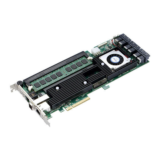
- Page 12 HARDWARE INSTALLATION Figure 2-2, ARC-1883i Top View Connector Type Description 1. (J1) Manufacture Purpose Port 12-pin header 2. (J2) Flash-based/Battery Backup Module Connector 14-pin box header 3. (J3) C/LCD Connector 7-pin header 4. (J4) Global Fault/Activity LED 4-pin header 5. (J5) Individual Activity (HDD) LED Header 4-pin header 6.
- Page 13 HARDWARE INSTALLATION Figure 2-3, ARC-1883LP Top View Connector Type Description 1. (J1) Manufacture Purpose Port 12-pin box header 2. (J2) Flash-based/Battery Backup Module Connector 14-pin header 3. (J3) Global Fault/Activity LED 4-pin header 4. (J4) Individual Fault/Activity LED Header 8-pin header 5.
- Page 14 HARDWARE INSTALLATION Figure 2-4, ARC-1883x Top View Connector Type Description 1. (J1) Manufacture Purpose Port 12-pin header 2. (J2) Flash-based/Battery Backup Module Connector 14-pin box header 3. (J3) C/LCD Connector 7-pin header 4. (J4) Ethernet Port RJ45 5. (SCN1) Mini SAS HD 5-8 Ports (External) SFF-8644 6.
- Page 15 The 12Gb/s SAS RAID controller can be installed in an universal PCIe slot and requires a motherboard that: ARC-1883 series 12Gb/s SAS RAID controller requires: • Comply with the PCIe 3.0 x8 lanes It can work on the PCIe 3.0 x1, x4, x8, and x16 signal with x8 or x16 mechanical slot M/B.
-
Page 16: Installation
HARDWARE INSTALLATION caused by electrostatic discharge, observe the following precau- tions: • Do not remove the 12Gb/s SAS RAID controller from its anti- static packaging until you are ready to install it into a computer case. • Handle the 12Gb/s SAS RAID controller by its edges or by the metal mounting brackets at its each end. - Page 17 HARDWARE INSTALLATION physical memory configuration for ARC-1883ix series is one 240- pin DIMM socket for 2GB(default) up to 8GB DDR3-1866, 1Rx8, ECC module or 8GB, DDR3-1600, 2Rx8, ECC module. Step 4. Install the 12Gb/s SAS RAID Controllers To install the 12Gb/s SAS RAID controller, remove the mounting screw and existing bracket from the rear panel behind the selected PCIe 3.0 slot.
- Page 18 HARDWARE INSTALLATION installed. Be sure that the power is connected to either the cage backplane or the individual drives. In the backplane solution, SAS/SATA drives are directly connected to 12Gb/s SAS system backplane or through an expander board. The number of SAS/SATA drives is limited to the number of slots available on the backplane.
- Page 19 HARDWARE INSTALLATION Step 6. Install SAS Cable This section describes how to cable a controller to the drive or backplane. Figure 2-7, Connecting to HDD Figure 2-8, Connecting to Backplane...
- Page 20 HARDWARE INSTALLATION Step 7. Connect Power to the Controller (ARC-1883ix only) There is a 6-pin PCI-E connector on the ARC-1883ix labelled J4. You must plug in a PSU’s PCI-E cable at all times to supply enough stable power for the controller. Figure 2-9, Connect Direct from Power Supply If your power supply doesn’t have a 6 pin PCI-E power cable then you can use the adapter to convert two 4 pin peripheral power...
- Page 21 HARDWARE INSTALLATION Figure 2-10, Connect through HDD/CD Cable Step 8. Install the LED Cable (Optional) The preferred I/O connector for server backplanes is the Mini SAS HD SFF-8643 connector. This connector has eight signal pins to support four SAS/SATA drives and six pins for the SGPIO (Serial General Purpose Input/Output) side-band signals.
- Page 22 SFF-8448 specification. The SFF-8448 sideband signals cable is reserved for the backplane with header on it. The following signal defines the sideband connector which can work with Areca sideband cable on its Mini SAS HD SFF-8643 to 4xSATA cable.
- Page 23 HARDWARE INSTALLATION wrong LED which causes the user to hot swap the wrong drive. This could result in failure and loss of system data. Step 11. Power up the System Thoroughly check the installation, reinstall the computer cover, and reconnect the power cord cables. Turn on the power switch at the rear of the computer (if equipped) and then press the power button at the front of the host computer.
- Page 24 For Intel-based Mac system: Areca controller has supported the EFI BIOS on the PCIe 3.0 12Gb/s SAS RAID controller. You have other alternatively to add volumes on the Intel-based Mac bootable device listing. You can follow the following procedures to add 12Gb/s SAS RAID controller on the Mac bootable device listing.
-
Page 25: Sas Cables
HARDWARE INSTALLATION 2.4 SAS Cables You can connect the end devices to each other through direct cables or through the SAS expander/backplane connections. The 12Gb/s SAS RAID controller supports daisy-chain expansion up to 8 enclosures. The following is an example of some internal SAS/SATA cables and an external SAS cable. -
Page 26: Mini Sas Hd Sff-8643 To 4Xsff-8482 Cable
HARDWARE INSTALLATION 2.4.2 Mini SAS HD SFF-8643 to 4xSFF-8482 Cable These controllers can be installed in a server RAID enclosure with out a backplane. The kind of cable will attach directly to the SAS disk drives. The following diagram shows the picture of Mini SAS HD SFF-8643 to 4xSFF-8482 cables. -
Page 27: Mini Sas Hd Sff-8644 Cable
HARDWARE INSTALLATION 2.4.4 Mini SAS HD SFF-8644 Cable The Mini SAS HD SFF-8644 cables are used for connection be- tween the 12Gb/s SAS controller external connectors and con- nectors on the external drive boxes or drive expanders (JBOD). The 12Gb/s SAS controller has Mini SAS HD SFF-8644 external connector, each of them can support up to four SAS/SATA sig- nals. - Page 28 HARDWARE INSTALLATION 1. Individual Activity/Fault LED and Global Indicator Con- nector Most of the backplane has supported the HDD activity from the HDD. The 12Gb/s SAS RAID controller also provides the fault activity for fault LED. Connect the cables for the drive fault LEDs between the backplane of the cage and the respective connector on the 12Gb/s SAS RAID controller.
- Page 29 HARDWARE INSTALLATION Figure 2-16, ARC-1883i LED Indicator Connector Figure 2-17, ARC-1883LP LED Indicator Connector Figure 2-18, ARC-1883x LED Indicator Connector...
- Page 30 Areca LCD module for information, status indication, or menus or Card LED indicator for status message. This interface can also cascade to another Areca serial bus accessories for the additional status display. The following picture and table are the serial bus signal name description for LCD &...
-
Page 31: Hot-Plug Drive Replacement
HARDWARE INSTALLATION Figure 2-19, Connect to LCD Status Panel 2.6 Hot-plug Drive Replacement The RAID controller supports the ability of performing a hot-swap drive replacement without powering down the system. A disk can be disconnected, removed, or replaced with a different disk without taking the system off-line. -
Page 32: Summary Of The Installation
HARDWARE INSTALLATION Note: The capacity of the replacement drives must be at least as large as the capacity of the other drives in the raid set. Drives of insufficient capacity will be failed immediately by the RAID controller without starting the “Automatic Data Rebuild”. 2.7 Summary of the installation The flow chart below describes the installation procedures for 12Gb/s SAS RAID controllers. - Page 33 CLI (Command Line Interface) lets you set up and manage RAID controller through a command line interface. CLI performs many tasks at the command line. You can download CLI manual from Areca website or software CD <CDROM>\ DOCS directory. SNMP Manager Console Integration...
- Page 34 Since the 12 Gb/s SAS RAID controller is already installed in the host system, no extra connection is necessary. Just load the necessary in-band Areca SNMP extension agent for the controllers. Before launching the SNMP agent in...
Need help?
Do you have a question about the ARC-1883 Series and is the answer not in the manual?
Questions and answers