
Subscribe to Our Youtube Channel
Related Manuals for MFZ Ovitor FS 345


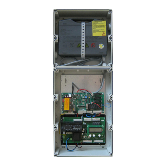
Summary of Contents for MFZ Ovitor FS 345
- Page 1 Operating Instructions for FS 345 with FS 101 and CS 300 FS FS 345 Door Controls / Rev.A 0.0 – 1...
-
Page 2: Table Of Contents
Reference to a check that needs to be carried out. REFERENCE Reference to separate documents that must be observed. Instruction requiring action − List, itemisation – Reference to other sections of this document 2 – FS 345 Door Controls / Rev. A 0.0... -
Page 3: General Safety Instructions
- risk assessment and risk reduction) supply before carrying out any electrical work. It must be ensured that the electricity supply remains disconnected for the duration of the work. − Local protective regulations must be complied with. FS 345 Door Controls / Rev.A 0.0 – 3... -
Page 4: Overview Of Products
The following housing models are available: − Housing with OPEN - STOP - CLOSE buttons − Housing with ON/OFF key switch − Housing with main switch − Housing with emergency OFF switch The operating instructions describe the connection options and models of the FS 345 control. 4 – FS 345 Door Controls / Rev. A 0.0... -
Page 5: Commissioning
Before switching on the control for the first time, a check must be carried out after completing the wiring to ensure that all the motor connections at the motor and at the con- trol is securely fixed. All control voltage inputs are galvani- cally isolated from the supply. FS 345 Door Controls / Rev.A 0.0 – 5... - Page 6 Malfunctions due to incorrect installation of the X2: Terminal block for motor battery! To prevent deep discharge of the rechargeable battery, Connection: the battery should not be connected to the FS 101 circuit − Connect the control to the mains power supply. board until the door is put into operation. To prevent errors, − Connect the control to the motor. the battery must be connected to the FS 101 circuit board − Cable groups must be secured close to their relevant termi- before the connection is made to the mains power supply. nals using a cable tie. 6 – FS 345 Door Controls / Rev. A 0.0...
- Page 7 FS 101 - CS 300 FS (ready-wired) FS101-P1-1 FS 345 Door Controls / Rev.A 0.0 – 7...
- Page 8 T1: 230 V transformer X1: Terminal block for mains connection Connection: X2: Terminal block for motor − Connect the control to the mains power supply. − Connect the control to the motor. Connection: − Cable groups must be secured close to their relevant termi- − Connect the control to the mains power supply. nals using a cable tie. − Connect the control to the motor. − Cable groups must be secured close to their relevant termi- nals using a cable tie. 8 – FS 345 Door Controls / Rev. A 0.0...
- Page 9 Command and safety devices can be connected via terminals X3 and X4. X3 / CS 300 FS - DOWN SWITCH - Impulse button - UP SWITCH - STOP button - Emergency off, slack rope switch, wicket door contact, draw in protection X6 / CS 300 FS - Sockets for internal ON-OFF switch - Sockets for internal 3-button input unit X7 / CS 300 FS STOP OPEN CLOSE FS 345 Door Controls / Rev.A 0.0 – 9...
- Page 10 Button Button Button STOP OPEN CLOSE OPEN CLOSE OPEN / STOP / CLOSE buttons Impulse button key switch (4-lead solution) (sequence control) Button Button Button Button STOP OPEN CLOSE IMPULSE 10 – FS 345 Door Controls / Rev. A 0.0...
- Page 11 Drive-through photoelectric barrier* safety device* Leading photoelectric barrier +12V DC HALF OPEN limit switch Signal Adjustment of the pre-limit switch CLOSE for the leading photoelectric barrier − On the CS 300 FS, set the mode for relay 1 to 11 (pre-limit HALF OPEN limit switch switch CLOSE) − Drive the door in the “close” direction until the leading photocell just touches the ground. − In the input menu, set the pre-limit switch CLOSE to this position * effective in down direction only FS 345 Door Controls / Rev.A 0.0 – 11...
- Page 12 Button S303 K04 Auxiliary motor relay K05 Motor brake relay K06 OPEN/CLOSE command relay K04 K05 K06 K07 K08 K09 K07 Upper switch relay K07 Lower switch relay K09 Stop relay FS 101 circuit board K10 Operation / error relay K11 Emergency closing relay K12 Closing edge safety device (SKS) relay 12 – FS 345 Door Controls / Rev. A 0.0...
- Page 13 Change the DIP switch positions as required Switch on the rechargeable battery voltage FD (FDF, FTA, FDS) operators Switch on the mains voltage DIP 1 OFF 1. FD (FDF, FTA and FDS) door operators with * version HY only a 24V DC auxiliary motor and 24V DC motor brake (FDF 5). In emergency mode, the door is closed via the 24V DC auxiliary motor. The power supply comes from the mains adapter on the FS 101 circuit board; if the mains power is interrupted, power is supplied from the rechargeable battery. FS 345 Door Controls / Rev.A 0.0 – 13...
- Page 14 Potential-free relay INPUT FIRE ALARM 24 V DC / 50 mA 1 2 3 4 5 6 Potential-free relay OPEN / CLOSE command Motor brake for FT / FDF operators* Auxiliary motor* * refer to the appendix for connection details for operators FT 3 and FDF 60 14 – FS 345 Door Controls / Rev. A 0.0...
- Page 15 DIP switches 1 and 3. (See 12 and 13.1 for wiring and function) 5.14 Messages Terminal strip X07 Terminal strip X09 K10 operation / error relay K12 closing edge safety edge (SKS) relay X07/FS101 X09/FS101 In normal operation contact closed, opens in the event of an error. Potential-free switching contact, displays status of CESD (SKS) Rechargeable battery fault / mains power failure: switches if the battery is defective or if the battery voltage is less than 19V. FS 345 Door Controls / Rev.A 0.0 – 15...
-
Page 16: Limit Switches
X10/CS300 FS* Safety circuit CLOSE OPEN 1 Limit switch OPEN 2 Limit switch CLOSE 3 Pre-limit switch CLOSE 5 Thermal protection, motor* 6 Emergency operation (normally closed contact)** 7 Safety limit switch CLOSE 8 Safety limit switch OPEN * ready wired ** ready wired if supplied with operator 16 – FS 345 Door Controls / Rev. A 0.0... - Page 17 10. After the trial run, check the tightness of the fastening screws. 11. Auxiliary limit switches 1 and 6 have a potential-free changeover contact 1. Additional OPEN limit switch green 2. Limit switch OPEN green 3. Safety limit switch OPEN 4. Safety limit switch CLOSED 5. Limit switch CLOSED white 6. Additional limit switch CLOSED white FS 345 Door Controls / Rev.A 0.0 – 17...
-
Page 18: Programming With The Lcd Monitor
After switching the control on, it is in INITIALISATION mode. they are triggered as soon as the control limit switches are The display shows INIT PHASE and the control is not yet ready crossed. for use. This phase lasts approx. 5 seconds. 10. After the trial run, check that the fastening screws are cor- rectly tightened. 11. Auxiliary limit switches 1 and 6 have a potential-free changeover contact 18 – FS 345 Door Controls / Rev. A 0.0... - Page 19 The door can be damaged if driven beyond the end posi- tion. Fine adjustments can be made in the INPUT operating mode. Display: − Displays the travel limit value Operating mode 3: INPUT In the INPUT operating mode, the values of various param- eters can be altered. Display: − Displays the selected parameter − Displays the current value or status FS 345 Door Controls / Rev.A 0.0 – 19...
-
Page 20: Navigator (Lcd Monitor Only)
Navigator (LCD monitor only) 20 – FS 345 Door Controls / Rev. A 0.0... - Page 21 FS 345 Door Controls / Rev.A 0.0 – 21...
-
Page 22: Overview Of Functions
The door is driven to the CLOSED end position CLOSE AUTOMATIC The door stands between the end positions STANDBY AUTOMATIC O The door stands at the OPEN end position STANDBY AUTOMATIC o The door stands at the PART OPEN position ("before-end position" up) STANDBY AUTOMATIC U The door stands at the CLOSED end position STANDBY AUTOMATIC u The door stands at the PART CLOSED position ("before-end position" down) STANDBY 22 – FS 345 Door Controls / Rev. A 0.0... - Page 23 (with a CESD (SKS) the brake is deactivated) MOD18: Red light flashes as a warning RELAY 4 MOD 19 MOD19 MOD19: CESD (SKS) DW-TEST ON: Pressure switch testing is active OFF: Pressure switch testing is not active DELAY ON: Gives warning before opening OPEN OFF: Immediate opening FS 345 Door Controls / Rev.A 0.0 – 23...
- Page 24 - Stop systems in the operator OFF: interrupted (fault) S-POINT1 - S top button on the control OFF: activated (keypad on cover) not activated S-POINT2 Pre-limit switch CLOSE OFF: activated not activated CYCLE Door cycle counter Displays number of door cycles 24 – FS 345 Door Controls / Rev. A 0.0...
- Page 25 LED OFF Drive command open/close on CS 300 FS is not active (output X04/ 5,6) yellow LED limit switch OPEN LED ON Limit switch OPEN not confirmed (output X05/1,2) LED OFF - Limit switch OPEN confirmed - Emergency operation is active yellow LED limit switch CLOSED LED ON Limit switch CLOSED not confirmed (output X05/3,4) LED OFF Limit switch CLOSED confirmed FS 345 Door Controls / Rev.A 0.0 – 25...
- Page 26 Check the safety circuit of the door operator Flashes 6 times HY leak (version FS 345 HY)) Check the hydraulic system Flashes 7 times SKS defective at OPEN end position Check SKS Flashes 8 times Door has been closed due to an error 26 – FS 345 Door Controls / Rev. A 0.0...
- Page 27 The closing edge safety device was activated cable Remove obstruction from path of door ERROR PRESSURE SWITCH TESTING The pressure sensor is not triggered at the Check the pressure sensor, spiral cable and profile CLOSED end position Check the setting for the CLOSED end position Battery No mains power supply Check mains power supply (L, N) Standby Emergency operation FS 345 Door Controls / Rev.A 0.0 – 27...
- Page 28 Connection between CS 300 FS + FS 101 In the event of a power cut: closes after 60 minutes CS 300 FS FS101 Battery 24 V DC Relay 4 K05 K06 K07 K08 K09 28 – FS 345 Door Controls / Rev. A 0.0...
- Page 29 2.5 seconds. Only then is power supplied to the motor brake again and the door is held in position. Repeat steps 2 to 6 entering different values for timer 2 until optimum results are achieved. 8. The CLOSE safety limit switch must be set accordingly. FS 345 Door Controls / Rev.A 0.0 – 29...
-
Page 30: Rechargeable Battery And Battery Charger
1. the battery test is started – LED indicator 2. The integrated buzzer sounds 3. After 2 seconds, the door is driven to the CLOSED end position 4. The buzzer stops 5. – LED indicator 6. The buzzer sounds once 7. The test is over 30 – FS 345 Door Controls / Rev. A 0.0... - Page 31 The door control cannot operate during this charging period. This charging status is indicated via the recharge LED and can be interrupted by pressing the RESET button. Lights up Flashes alternately FS 345 Door Controls / Rev.A 0.0 – 31...
- Page 32 − Danger of fire and short-circuit (due to electric shock in moist conditions) To prevent any danger: − Ensure that the area is adequately ventilated. − Avoid fire and naked lights. − Use the plug-in power pack only in dry rooms. − Protect the device from moisture. 32 – FS 345 Door Controls / Rev. A 0.0...
- Page 33 FS 345 Door Controls / Rev.A 0.0 – 33...
-
Page 34: Motor Brake And Auxiliary Motor
11. Motor brake and auxiliary motor 11.1 Motor brake connection diagram for FT 3 / FT 4 / FT 5 operator CS 300 FS auxiliary mains adapter 24 V DC 24 V DC mo- tor brake 34 – FS 345 Door Controls / Rev. A 0.0... - Page 35 11.2 Auxiliary motor connection diagram for FDF 60 operator Battery FDF 60 power relay auxiliary motor auxiliary motor FS 345 Door Controls / Rev.A 0.0 – 35...
-
Page 36: Technical Data
Once contacts have been used for power cir- cuits, they can no longer be used for extra-low current circuits. Temperature range: Operation: +5°C … +55°C Storage: -20°C … +85°C Air humidity: Up to 80% with no condensation Vibrations: Low-vibration mounting, e.g. on a masonry wall Type of protection: IP 54 Weight: approx. 10.5 kg 36 – FS 345 Door Controls / Rev. A 0.0... -
Page 37: Ec Declaration Of Incorporation
- Immunity for industrial environments Position of signatory DIN EN 61000-6-3 Management Electromagnetic compatibility (EMC) - Part 6-3: Generic standards - Emission - standard for residential, com- mercial and light-industrial environments DIN EN 60335-1 Household and similar electrical appliances - Safety - Part 1: General requirements DIN EN 60335-2-103 Household and similar electrical appliances - Safety - Part 2-103: Particular requirements for drives for gates, doors and windows FS 345 Door Controls / Rev.A 0.0 – 37... - Page 38 38 – FS 345 Door Controls / Rev. A 0.0...
- Page 39 FS 345 Door Controls / Rev.A 0.0 – 39...
- Page 40 #1700009439...
Need help?
Do you have a question about the FS 345 and is the answer not in the manual?
Questions and answers