Apollo XPander XPA-IN-14011-APO Installation Manual
Input/output unit
Hide thumbs
Also See for XPander XPA-IN-14011-APO:
- Commissioning manual (14 pages) ,
- Commissioning manual (19 pages)
Table of Contents
Advertisement
Quick Links
Battery Type
6x AA, 1.5V Alkaline Duracell Procell (MN1500, LR6)
When replacing batteries, allow the device to power down for a period of two minutes
before installing replacements.
Note: When replacement batteries are required, all batteries must be replaced together.
Technical Data
Operating voltage
Operating temperature
Relay rating
Switch closed resistance
End-of-line resistor
Functional Testing
The interface and associated devices should be commissioned according to the commis-
sioning guide; PP2286.
© Apollo Fire Detectors Limited 2009-2010
Apollo Fire Detectors Limited, 36 Brookside Road, Havant, Hampshire, PO9 1JR, UK
Tel: +44 (0) 23 9249 2412 Fax: +44 (0) 23 9249 2754
Email: techsales@apollo-fire.co.uk Website: www.apollo-fire.co.uk
PP2367/2010/Issue 2
2.8-5VDC
–10°C to +50°C
2A at 30V DC
4K7Ω
20KΩ
XPander Input/Output Unit
Installation Guide
General
Do not install any XPander equipment until a full site survey has been completed using the
XPander site survey tool. A maximum of 5 interfaces are permitted for each site. For sites
that require more than 5 interfaces please contact Apollo. All installation engineers must
have had certified XPander training.
The XPander Input/Output (I/O) Unit variants are available under the following part
numbers:
Part Number
XPA-IN-14011-APO
XPA-IN-14012-APO
The installation must conform to BS5839-1:2008 (or applicable local codes). The XPander I/O
Unit is suitable for indoor use only.
Compatibility
The XPander I/O Unit requires interface to be version 4B or higher.
Installation of XPander I/O Unit
Ensure that the XPander I/O Unit is sited in accordance with the survey and design require-
ments. The recommended minimum distance to any electrical equipment is two metres
radius (three dimensionally).
1.
Calculate the number of cable entries and drill holes for cable glands in the lower
portion of the enclosure accordingly (Fig 1). Remove and replace the PCB if necessary
using anti-static precautions to avoid damaging the electronics.
2.
Mount the XPander I/O enclosure using suitable fixings (No. 6/3.5mm screw clearance,
see Fig 1 for fixing positions) and connect all wiring.
3.
Set the address and mode of relay operation; normal or fail safe (see address setting
overleaf)
4.
Fit the power jumper shorting link and commission the unit according to the XPander
commissioning guide PP2286.
LED Indication
In order to aid with commissioning, the XPander I/O unit has LED indication of input and
output status. By default, LED indication is disabled to preserve battery life. LED indication
is enabled by pressing the LED Enable button once. LED indication will remain active for
10-minutes unless the button is pressed again.
Relay on
Illuminated red when relay is energised
Switch Closed
Illuminated red when monitored field contact activated
Fault
Illuminated yellow when input wiring is open or short circuit
Description
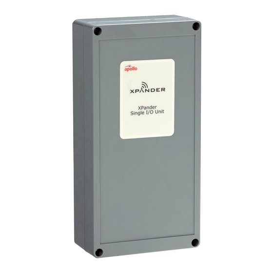
Single Input/Output Unit
Dual Input/Output Unit
1
Advertisement
Table of Contents

Subscribe to Our Youtube Channel
Related Manuals for Apollo XPander XPA-IN-14011-APO


Summary of Contents for Apollo XPander XPA-IN-14011-APO
- Page 1 Do not install any XPander equipment until a full site survey has been completed using the XPander site survey tool. A maximum of 5 interfaces are permitted for each site. For sites that require more than 5 interfaces please contact Apollo. All installation engineers must have had certified XPander training.
- Page 2 IP + OUTPUT 1 FIXING POSITION 1 FIXING POSITION 2 © Apollo Fire Detectors Limited/2009-10/TB Fig 2 - Wiring details Address Setting The address of the XPander I/O Unit is set using the first seven segments of the DIL switch.
Need help?
Do you have a question about the XPander XPA-IN-14011-APO and is the answer not in the manual?
Questions and answers