
Subscribe to Our Youtube Channel
Related Manuals for Lexicomm ViLX-228

Summary of Contents for Lexicomm ViLX-228
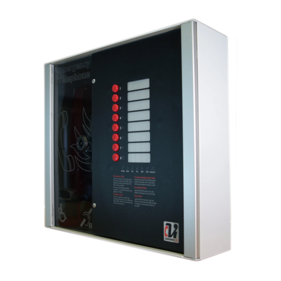
- Page 1 Lexicomm ViLX-228 EVCS Master Station Installation and Commissioning Manual Version 6 September 2017...
-
Page 2: Table Of Contents
5.9 Powering up procedure ....................... 12 5.10 Powering down procedure ....................12 6. Set up procedure ........................13 6.1 ViLX-228 Master Station Display PCB Dipswitch Settings ............13 6.2 Adding a Line Card ......................14 6.3 Removing a Line card ......................14 6.4 Adding a ViLX-228 Repeater Station .................. -
Page 3: Introduction
ViLX-228 Master Station also applies to the ViLX-228 Repeater Station, unless specified otherwise. The ViLX-228 Master Station has been designed for radial star topology. In most cases this will reduce the cable requirements for all ring-based systems. The topology consists of spurs formed of 1 off two core 1.5mm CSA cables (soft skin enhanced up to 500m per leg, MICC 200m per leg) to each... -
Page 4: Important Safety Information
Each ViLX-228 Master/Repeater Station requires a 3A spur, returning to a breaker clearly marked “EVCS DO NOT TURN OFF”. If the ViLX-228 Master Station and the ViLX-228 Repeater Station are distributed around a site, it is essential that both ViLX-228 Stations are on the same mains phase, as they are classified TEN 230V. -
Page 5: Unpacking The Unit
4. Unpacking the Unit Remove the ViLX-228 Master Station from its packing, and check the contents against the following list: ViLX-228 Master Station. • • Installation & maintenance manual (this document). User Guide & logbook. • • Accessory pack with the following contents:- 1 number 2.5mm AF Hex Key. -
Page 6: Installation
5. Installation Prior to mounting the ViLX-228 Master Station, it should be decided if the field wiring is to be run on the surface or concealed. . There are 14 knockouts on the top and 2 slotted entries with a dedicated mains supply entry at the rear. -
Page 7: Connecting The Vilx-228 Master Station
5.3.1 Fire Telephone system Any system using Type A outstations must use enhanced grade cabling throughout for all wiring, including the mains supply to the ViLX-228 Master Station. 5.3.2 Disabled Refuge EVC System For buildings less than 30m in height, or any building with sprinklers fitted, standard grade fire resistant cable may be used to wire Type B outstation and the mains supply to the Master Controller;... -
Page 8: Vilx-228 Master Station Wiring
5.4.1 ViLX-228 Master Station Wiring The wiring for a ViLX-228 Master Station is shown in the schematic below. Page 8 of 24 Document PViLX228 7001-06 Rev 6 2017... -
Page 9: Vilx-228 Master/Repeater Stations Wiring In Ring
If two ViLX-228 Stations are wired in Master/Repeater format, with the outstations shared between both the Master Station and the Repeater Station, the ViLX-228 system has to be wired as a ring, with each outstation connected via a radial circuit to either the Master Station or Repeater Station, as shown in the schematic below. -
Page 10: Mains Connection
Each ViLX-228 Master/Repeater Station requires a 3A spur, returning to a breaker clearly marked “EVCS DO NOT TURN OFF”. If the ViLX-228 Master Station and the ViLX-228 Repeater Station are distributed around a site, it is essential that both ViLX-228 Stations are on the same mains phase, as they are classified TEN 230V. -
Page 11: Type A Outstation
5.7.1 Type A outstation Note: The Earth screen should be sleeved and connected to the terminal block in the controller, and the earth stud in the Type A outstation. 5.7.2 Type B outstation Note: The Earth screen should be sleeved and connected to the terminal block in the controller, and the earth connection in the metal back box (if a plastic back-box is used cut the earth back and insulate at the outstation) 5.7.3 ACA Accessible Toilet Kit... -
Page 12: Auxiliary Connections
To power up the ViLX-228 Master Station, carefully check all internal wiring before applying mains power to the ViLX-228 Master Station. Once the ViLX-228 Master Station is powered, the battery can be attached using the battery leads supplied. When attaching the battery, always attach the Positive (Red+) terminal first. -
Page 13: Set Up Procedure
6. Set up procedure The ViLX-228 Master Station has various site configurations which are configured using the dipswitch located on the rear of the Display PCB. 6.1 ViLX-228 Master Station Display PCB Dipswitch Settings Line Line Line Line Network Reserved Remarks 1&2... -
Page 14: Adding A Line Card
Station in any combination, as long as the Line Cards do not occupy the same position on the Exchange PCB in both the ViLX-228 Master Station and the ViLX-228 Repeater Station, i.e. if a Line Card is in position 1 (Lines 1&2) on the ViLX-228 Master Station, then no Line Card can be placed into position 1 (Lines 1&2) on the ViLX-228 Repeater Station. -
Page 15: Vilx-228 Master Station Exchange Pcb Dipswitch Settings
ViLX-228 Master Station Exchange PCB Dipswitch Settings The ViLX-228 Master Station can be integrated with a ViLX-TMS Master Station to form part of a Lexicomm site wide network where the ViLX-228 Master Station provides a local control and wiring position reporting back to the ViLX-TMS. -
Page 16: System Menus
7. System Menus 7.1 Fault Accept Before accepting faults, the fault must be noted in the log book, along with the time the fault was reported. To accept the fault, enter either the access level 2 (code: 1664) or access level 3 (code: 1812) menu, then press zone button 1. -
Page 17: Engineer Walk Test
7.5 Engineer Walk Test The engineer walk test mode enables all connected outstations, including “Assist Call”, to be tested for correct operation by a single engineer without needing to return to the Master Station to reset the calls, until complete. Enter the access level 3 engineer code (1812) then press zone button 5. -
Page 18: In Use Relay Options
8.5 Conference Call Depending upon the number of Line Cards fitted in the ViLX-228 Master Station, up to five lines can be connected to the conference call at any one time. To receive a call, see 8.1. To make a call to an individual outstation, see 8.2. -
Page 19: Acknowledging "Assist Call" Alarms
8.6 Acknowledging “Assist Call” alarms When an “Assist Call” goes into alarm, the appropriate zone LED will flash blue, and a two-tone buzzer sounds to indicate that an “Assist Call” alarm has been operated. To acknowledge the alarm, press the corresponding zone button, and the blue LED will illuminate continuously with an intermittent buzzer tone every 15 seconds. -
Page 20: Power Supply And Cpu Indicator Summary
9.2 Power supply and CPU indicator Summary General Description Mains OK Flash Flash Mains failure Battery OK Flash Flash Battery open circuit Flash Battery short circuit Flash Flash Battery high impedance Flash PSU processor fail ... -
Page 21: Commissioning Procedure
Power up the ViLX-228 Master Station using mains only, fed from a 3A fuse fitted in an unswitched fused spur. The AC power indicator will be illuminated, and the DC power indicator is extinguished. The PSU fault and General fault indicators will be illuminated. -
Page 22: Outstation Zone Template
12. Outstation zone template There is space to the right of each outstation zone indicator to name the location of the outstation. At the rear of the display door there is a slot located in the centre above the display PCB; the outstation zone template can be inserted here. - Page 23 Notes Page 23 of 24 Document PViLX228 7001-06 Rev 6 2017...
-
Page 24: Technical Specification
350 x 300 x 95 Entries 14 knockouts top, 2x rear slots Flush Cutout 352 x 302 x 85 deep The Lexicomm ViLX-228 EVCS is designed and manufactured in the UK by: Vox Ignis Ltd, Unit 72T Wearfield Enterprise Park East, Sunderland, SR5 2TH.
Need help?
Do you have a question about the ViLX-228 and is the answer not in the manual?
Questions and answers