Table of Contents
Advertisement
Quick Links
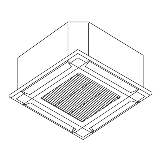
AIR CONDITIONER
Compact cassette type
Contents
1. SAFETY PRECAUTIONS ...................................................................... 1
1.1. Precautions for using R32 refrigerant ............................................. 2
2. PRODUCT SPECIFICATION ................................................................ 4
2.1. Installation tools .............................................................................. 4
2.2. Accessories .................................................................................... 4
2.3. Cassette grille accessories ............................................................. 4
2.4. Pipe requirement ............................................................................ 5
2.5. Electrical requirement ..................................................................... 5
2.6. Optional parts ................................................................................. 5
3. INSTALLATION WORK ......................................................................... 5
3.1. Selecting an installation location .................................................... 5
3.2. Installation dimensions ................................................................... 5
3.3. Installing the unit ............................................................................. 6
3.4. Drain installation ............................................................................. 6
3.5. Pipe installation .............................................................................. 7
3.6. Electrical wiring ............................................................................... 8
3.7. Remote controller setting ...............................................................11
4. CASSETTE GRILLE INSTALLATION ...................................................11
4.1. Remove the intake grille ................................................................11
4.2. Installing the panel to indoor unit ...................................................11
4.3. Attach the intake grille .................................................................. 12
5. OPTIONAL INSTALLATION WORK .................................................... 12
5.1. Optional kit installation .................................................................. 12
5.2. External input and output .............................................................. 12
5.3. Remote sensor (Optional parts) ................................................... 13
5.4. Other optional parts ...................................................................... 13
5.5. Optional parts cable binding ......................................................... 13
6. REMOTE CONTROL INSTALLATION ................................................. 14
6.1. Group control ................................................................................ 14
6.2. Multiple remote control ................................................................. 15
6.3. Simultaneous multi-system operation ........................................... 15
7. FUNCTION SETTING ......................................................................... 16
7.1. Function details ............................................................................ 16
8. CHECK LIST ....................................................................................... 18
9. TEST RUN ........................................................................................... 18
9.1. Check items .................................................................................. 18
9.2. Operation method ......................................................................... 18
10. FINISHING ........................................................................................ 18
10.1. Installing heat insulation ............................................................. 18
11. CUSTOMER GUIDANCE .................................................................. 18
12. ERROR CODES ................................................................................ 18
NOTES: This manual describes how to install the air conditioner described above.
Handling and installation shall only be done by professionals as outlined in this
manual.
1. SAFETY PRECAUTIONS
• Be sure to read this manual thoroughly before installation.
• The warnings and precautions indicated in this manual contain important information
pertaining to your safety. Be sure to observe them.
• Hand this manual, together with the operating manual, to the customer. Request the
customer to keep them on hand for future use, such as for relocating or repairing the unit.
Indicates a potentially or imminently hazardous situation
WARNING
which, if not avoided, could result in death or serious injury.
INSTALLATION MANUAL
[Original instructions]
Indicates a potentially hazardous situation that may result in
CAUTION
minor or moderate injury or damage to property.
• The appliance shall be installed, operated and stored in a room with a fl oor area larger
than X m
2
Amount of refrigerant charge
M (kg)
M ≤ 1.22
1.22 < M ≤ 1.23
1.23 < M ≤ 1.50
1.50 < M ≤ 1.75
1.75 < M ≤ 2.0
2.0 < M ≤ 2.5
2.5 < M ≤ 3.0
3.0 < M ≤ 3.5
3.5 < M ≤ 4.0
• Installation of this product must be done by experienced service technicians or profes-
sional installers only in accordance with this manual. Installation by non-professional
or improper installation of the product might cause serious accidents such as injury,
water leakage, electric shock, or fi re. If the product is installed in disregard of the
instructions in this manual, it will void the manufacturer's warranty.
• Do not turn on the power until all work has been completed. Turning on the power be-
fore the work is completed can cause serious accidents such as electric shock or fi re.
• If refrigerant leaks when you are working, ventilate the area. If the leaking refrigerant
is exposed to a direct fl ame, it may produce a toxic gas.
• Installation must be performed in accordance with regulations, codes, or standards for
electrical wiring and equipment in each country, region, or the installation place.
• Do not use means to accelerate the defrosting process or to clean, other than those
recommended by the manufacturer.
• This appliance is not intended for use by persons (including children) with reduced
physical, sensory or mental capabilities, or lack of experience and knowledge, unless
they have been given supervision or instruction concerning use of the appliance by a
person responsible for their safety. Children should be supervised to ensure that they
do not play with the appliance.
• To avoid danger of suffocation, keep the plastic bag or thin fi lm used as the packaging
material away from young children.
• The appliance shall be stored in a room without continuously operating ignition
sources (for example: open fl ames, an operating gas appliance or an operating
electric heater).
• Do not pierce or burn.
• Be aware that refrigerants may not contain an odour.
• Read carefully all safety information written in this manual before you install or use the
air conditioner.
• Install the product by following local codes and regulations in force at the place of
installation, and the instructions provided by the manufacturer.
• This product is part of a set constituting an air conditioner. The product must not be
installed alone or be installed with a device not authorized by the manufacturer.
• Always use a separate power supply line protected by a circuit breaker operating on
all wires with a distance between contact of 3 mm for this product.
• To protect the persons, earth (ground) the product correctly, and use the power cable
combined with an Earth Leakage Circuit Breaker (ELCB).
• This product is not explosion proof, and therefore should not be installed in an explo-
sive atmosphere.
• To avoid getting an electric shock, never touch the electrical components soon after
the power supply has been turned off. After turning off the power, always wait 5 min-
utes or more before you touch the electrical components.
• This product contains no user-serviceable parts. Always consult experienced service
technicians for repairing.
• When moving or relocating the air conditioner, consult experienced service technicians
for disconnection and reinstallation of the product.
• Do not touch the aluminum fi ns of heat exchanger built-in the indoor or outdoor unit to
avoid personal injury when you install or maintain the unit.
• Do not place any other electrical products or household belongings under the product.
Condensation dripping from the product might get them wet, and may cause damage
or malfunction to the property.
• Be careful not to scratch the air conditioner when handling it.
PART No. 9379124119-03
For authorized service personnel only.
WARNING
Minimum room area
2
X (m
)
-
1.45
2.15
2.92
3.82
5.96
8.59
11.68
15.26
(IEC 60335-2-40)
CAUTION
En-1
Advertisement
Chapters
Table of Contents

Subscribe to Our Youtube Channel
Related Manuals for Fujitsu AUXG-KVLA Series


Summary of Contents for Fujitsu AUXG-KVLA Series
-
Page 1: Table Of Contents
AIR CONDITIONER INSTALLATION MANUAL Compact cassette type PART No. 9379124119-03 [Original instructions] For authorized service personnel only. Indicates a potentially hazardous situation that may result in CAUTION minor or moderate injury or damage to property. WARNING • The appliance shall be installed, operated and stored in a room with a fl oor area larger than X m Amount of refrigerant charge Minimum room area... -
Page 2: Precautions For Using R32 Refrigerant
1.1. Precautions for using R32 refrigerant CAUTION 2-4 Presence of fi re extinguisher The basic installation work procedures are the same as conventional refrigerant (R410A, • If any hot work is to be conducted on the refrigeration equipment or any associated R22) models. - Page 3 CAUTION CAUTION 4-Repair to intrinsically safe components 10-Decommissioning • Do not apply any permanent inductive or capacitance loads to the circuit without • Before carrying out this procedure, it is essential that the technician is completely ensuring that this will not exceed the permissible voltage and current permitted for familiar with the equipment and all its details.
-
Page 4: Product Specification
Explanation of symbols displayed on the indoor unit or outdoor unit. Name and Shape Q’ty Name and Shape Q’ty This symbol shows that this appliance uses a fl ammable Operating manual Drain hose insulation refrigerant. WARNING If the refrigerant is leaked and exposed to an external igni- tion source, there is a risk of fi... -
Page 5: Pipe Requirement
2.4. Pipe requirement 3.1. Selecting an installation location Model Gas pipe size (thickness) [mm] Luquid pipe size (thickness) [mm] WARNING 07, 09, 12, 14 Ø 9.52 (0.80) Ø 6.35 (0.80) Select installation locations that can properly support the weight of the indoor unit. 18, 22, 24 Ø... -
Page 6: Installing The Unit
■ Discharge direction setting 3.3.2. Body installation • The discharge direction can be selected as shown below. (1) Install special nut A, then special nut B onto the hanging bolt. (Unit: mm) (2) Raise the body and mount its hooks onto the hanging bolt between the special nuts. 100 or more* (3)Turn special nut B to adjust the height of the body. -
Page 7: Pipe Installation
■ When lifting up drain pipe: NOTES: Check for drainage • Height of inclined pipe should be less than 700 mm from the ceiling. A rise dimension over this range will cause leakage. Pour about 1 liter of water from the position shown in the diagram or from the airfl ow outlet to the dew tray. -
Page 8: Electrical Wiring
■ Bending pipes 3.6. Electrical wiring CAUTION WARNING • To prevent breaking of the pipe, avoid sharp bends. • If the pipe is bent repeatedly at the same place, it will break. • Electrical work must be performed in accordance with this Manual by a person certifi ed under the national or regional regulations. -
Page 9: Indoor Unit
■ Simultaneous twin (18 model only) 3.6.1. Wiring system diagram ■ Standard pair Connection cable Junction box (Locally purchased) Indoor unit Connection cable Earth (Ground) line (Primary) Outdoor unit Indoor unit Outdoor unit Earth (Ground) line Power line Control line Earth (Ground) line Indoor unit (Secondary) - Page 10 Wired remote controller cable (3) Connect specifi ed wires securely, and fasten them so that there is no stress applied on the terminals. 3-wire type only (4) Use a screwdriver with an appropriate bit size to tighten the terminal screws. Using of Indoor unit screwdriver with inappropriate bit size will damage the screw heads, and the screws (Primary)
-
Page 11: Remote Controller Setting
■ Remote controller cable 4. CASSETTE GRILLE INSTALLATION DIP switch • Installation according to the Installation instruction sheet Cassette grille. • Be sure to confi rm there is no gap between the panel and main unit after installing the Cassette grille. Print circuit board (PCB) 4.1. -
Page 12: Attach The Intake Grille
(2) Connect the connector. *2: Other options (WLAN adapter, converters, etc.) may be connectable. Please refer to the technical data for details. Cable (display): WHITE NOTES: Options connecting to CN47 or CN65 cannot be used at the same time. Cable (louver): WHITE Cable (louver): RED 5.2. -
Page 13: Remote Sensor (Optional Parts)
5.2.2. External output 5.4. Other optional parts • A twisted pair cable (22AWG) should be used. Maximum length of cable is 25 m (82 ft.). • Use an external input and output cable with appropriate external dimension, depending 5.4.1. Connection method on the number of cables to be installed. -
Page 14: Remote Control Installation
(b) 3-wire type 6. REMOTE CONTROL INSTALLATION DIP switch (RC AD SW)...Factory setting “00” When connecting multiple indoor units to 1 standard wired remote controller, set the address at RC AD SW in sequence from “00”. 6.1. Group control Setting Setting range Switch 100 NOTES: Group control cannot be used together with W-LAN adapter. -
Page 15: Multiple Remote Control
■ Settings when simultaneous Multi is included (1) Wiring method (indoor unit to remote controller) Indoor unit (3) Remote controller setting 1. Turn on all of the indoor units. * Turn on the indoor unit with the R.C. address “00” last. Remote con- (Within 1 minute) troller cable... -
Page 16: Function Setting
Set the R.C. address (DIP switch setting) 7. FUNCTION SETTING Set the R.C. address of each indoor unit using the DIP switches on the indoor unit circuit board. (Refer to the following table and fi gure.) The DIP switches are normally set to make the R.C. address “00”. Perform the Function setting according to the installation conditions using the remote controller. - Page 17 ■ Room temperature control for indoor unit sensor ■ Room temperature sensor switching (Only for wireless remote controller) Depending on the installed environment, correction of the room temperature sensor may When using the Wired remote controller temperature sensor, change the setting to “Both” (01). be required.
-
Page 18: Check List
■ Setting record 10. FINISHING Record any changes to the settings in the following table. Setting description Setting value Filter sign 10.1. Installing heat insulation Ceiling height Outlet directions Cooling CAUTION Room temperature control for indoor unit sensor Heating • After checking for gas leaks (refer to the Installation Manual of the outdoor unit), Cooling Room temperature control for wired perform this section. - Page 19 Error display Error display OPERATION TIMER ECONOMY OPERATION TIMER ECONOMY Error code Description Error code Description lamp lamp lamp lamp lamp lamp (green) (orange) (green) (green) (orange) (green) Indoor unit PCB model • Discharge pressure sensor error ...
Need help?
Do you have a question about the AUXG-KVLA Series and is the answer not in the manual?
Questions and answers