Table of Contents
Advertisement
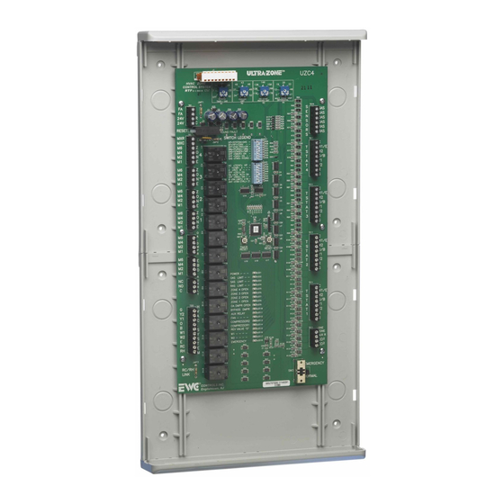
The UZC4 Universal Zone Control System allows you to easily
upgrade an inefficient single zone HVAC system, into an
Automated, Multi-zone, Energy saving, Comfort producing,
Safety Minded, HVAC system. With Superior design, Intuitive
firmware, Building Code Compliant support, Simple setup
options, and Easy to understand wiring, the UZC4 Zoning
system is the Designer/Contractors dream. Combined with
Patented EWC motorized dampers and practically any Off-the-
shelf Conventional or Heat Pump style Thermostats,
EWC has set a New Industry Standard in Large
Residential and Commercial HVAC Air Zoning Systems.
The main module controls four air zones
Zone
using 24 vac motorized air dampers and
Capacity
may be expanded up to 22 zones, using
ZXM2 Expansion Modules.
Compatible
The UZC4 will Control 2, 3 & 4 stage
Conventional, GeoThermal or Dual Fuel
HVAC
Heat pumps, without the need for dual
Systems
fuel kits. Also single or multi-stage Gas,
Oil, & Hydronic HVAC systems, with
single or two stage cooling and Constant
or Variable speed fan systems.
Compatible with most Off the shelf 1 or 2
Compatible
stage Conventional Heat/Cool or Heat
Thermostats
Pump Thermostats. All Mechanical,
Digital/Electronic, Dual Mode, and Internet
Compatible Thermostats that operate on
24vac. Battery powered or Power robbing
thermostats that draw less than 20 ma of
current are also compatible. Zone 1 will
accept One Zone Mode, Carbon Dioxide
Safety and Auxiliary/Dehumidify mode
inputs. See pages 9-11 & 14-17 for details.
Automatic
The UZC4 Zone system features
automatic changeover from any
Heat/Cool
thermostat allowing for individual zone
Changeover
comfort from the HVAC system.
The STATUS LED pulses as a steady
Status LED
heart beat to indicate active Micro-
processor status.
On board Multi-colored LED's will
System LEDs
illuminate to indicate system status,
HVAC system mode, and active / inactive
zone identification.
Damper 1 thru Damper 22 green LEDs
Damper LEDs
will indicate which zone dampers are
demanded to energize Open or Closed.
Operating
INPUT VOLTAGE: 19-30VAC 60 Hz
Power
Transformer 40-100VA MAX. NEC Class
2.
CURRENT DRAW: Max 22VA @ 24VAC.
OVER-CURRENT PROTECTION: 4.0
amp or 100VA.
TB-221
EWC Controls Inc. 385 Highway 33 Englishtown, NJ 07726 800-446-3110 FAX 732-446-5362
P/N 090375A0221
Revision S 09.04.12
Forced Air Zone Controls
See page 23.
See page 22 for details
©
Copyright
2004 EWC Controls Inc., All Rights Reserved
®
Model UZC4 Zone Control
Leave this bulletin on the job site for future reference!
J1
21
HVAC ZONE
14
CONTROl SYSTEM
7
OFF
STAGING
OAS
TIMER
R1
TB1
JMP1
FA
C1
C2
FA
24V
R
24V
C
D1
D2
LED19
RESET
TB2
GROUND FAULT
CB1
MXR
MXC
JMP2
F1
M6
D3
Z
M4
O
4
M2
N
M1
E
R5
D4
TB3
Z
M6
O
M4
3
N
M2
R6
D5
E
M1
TB4
M6
Z
M4
R7
O
D6
2
M2
N
M1
E
TB5
R8
M6
Z
D7
M4
O
1
M2
N
M1
E
R9
D8
TB6
O
M6
A
M4
D
M2
R10
M
D9
P
M1
R
TB7
M6
E
R11
M4
D10
B
M2
D
M1
A
TB8
R12
U
NC
D11
X
NO
R
C
L
Y
R13
D12
TB9
H
G
V
Y2
R14
D13
A
Y1
C
O
B
R15
W1
S
D14
W2
Y
E
S
RC
T
R16
RH
E
D15
M
R17
JMP3
D16
RH
RC
LINK
R18
E
W
C
CONTROLS INC.
Englishtown, NJ
Box Contents
Manual
and
Automatic
Thermal
Circuit
Breakers
.
Operating
Conditions
Indoor Fan
Control
140
26
43
28
40
46
130
150
19
120
160
35
37
49
12
110
170
42
5
34
52
COOLING
1ST
STAGE
MULTI
STAGE
DIFFERENTIAL
LIMIT
HEATING
LIMIT
R2
R3
R4
C54
C53
D17
R23
D18
R24
R25
D19
D20
R26
D21
R27
D22
R28
BANK1
HP
>
SYSTEM
>
GAS
R29
DF
<
HP
>
CONV
R50
R30
<
>
OFF
FAN PRG
ON
R31
R45
90
s
<
PURGE
>
180
s
R32
C3
OAS
<
STAGES
>
TMR
R33
OFF
<
50
%
R
>
ON
R46
R34
OFF
<
SAS
>
ON
R35
D23
GAS
<
FAN
>
HYDRO
R36
BANK2
U2
>
>
HC
TSTAT
HP
R37
1
<
CS#
>
2
R38
O
<
RV
>
B
R39
<
>
OFF
ZDL
ON
R40
C4
<
>
RA
AUX RLY
DA
R41
R83
OFF
<
RAS
>
ON
R42
U3
0
<
>
+10
RA LMT
R43
<
>
ANY
FAN CTRL
Z 1
R44
R85
C8
C5
U4
R87
U14
U15
C7
R47
C6
U5
R91
C16
R93
J2
U6
C18
R95
R48
U1
C17
C20
U7
Y1
R50
SW2
R99
SW1
C23
R58
U8
C21
R101
R51
TIMER
CPU
RESET
RESET
R103
C24
U9
U19
U18
U17
R107
LED1
R109
STATUS
LED2
OAS
LIMIT
R111
LED3
SAS
LIMIT
LED4
RAS
LIMIT
LED5
ZONE
4
OPEN
LED6
ZONE
3
OPEN
R115
LED7
ZONE
2
OPEN
LED8
ZONE
1
OPEN
R117
LED9
OA DMPR
OPEN
LED10
R119
BYPASS
DMPR
LED11
AUX RELAY
LED12
FAN
LED13
COMPRESSOR2
LED14
R123
COMPRESSOR1
LED15
REV
VALVE
LED16
R125
W1 HEAT
LED17
W2 HEAT
R127
LED18
EMERGENCY
C52
R52
Z1
R129
R134
R135
R130
R53
R56
R133
R54
R57
R55
R60
R63
R61
* UZC4 Zone Control Panel
* Supply Air Sensor
* Technical Bulletin TB221
* Mounting Hardware
The main UZC4 module has a Manual
Reset circuit breaker with a Ground
Fault Indicator that protects all
connected modules and thermostat
circuitry. All modules have separate
damper motor Thermal Breakers too.
They protect the damper motor circuitry
from shorts in the field wiring. The
breakers will not protect against shorts
in the HVAC system wiring.
CAUTION:
When the thermal
breaker is tripped it will get quite
hot. To reset the breaker: Shut off
power to the panel. Find and repair
the short. Restore the 24VAC power.
TEMPERATURE: -20° to 160°F (-29° to 71°C)
HUMIDITY: 0% - 95% RH Non-Condensing.
The UZC4 allows constant operation of
the Indoor Fan by Thermostat #1 only, or
by each individual thermostat. When
controlled by thermostat #1, All Zone
dampers will respond. When controlled
individually, Zones not calling
continuous fan will close.
E-Mail- info@ewccontrols.com
UZC4
33
40
47
R64
HEAT
TB10
R65
S
SAS
R66
E
SAS
R67
C25
N
OAS
R68
S
R69
C26
OAS
O
R70
RAS
R
R71
C27
RAS
R72
S
R73
TB11
R74
C
R75
C28
W1
R76
T
E
R77
C29
W2
S
R78
O
T
B
R79
C30
Y1
A
R80
Y2
T
R81
4
R
R82
G
C31
R84
C32
R86
TB12
C33
C
R88
W1
E
T
R89
W2
S
R90
O
T
B
C34
Y1
A
R92
Y2
C35
T
R94
R
3
C36
G
R96
R97
R98
C37
TB13
R100
C
C38
W1
E
T
R102
W2
C39
S
O
R104
T
B
Y1
A
R105
Y2
T
R106
R
2
C40
G
R108
C41
R110
C42
R112
TB14
R113
C
R114
W1
E
T
C43
W2
R116
S
C44
O
T
B
R118
A
Y1
C45
Y2
T
R120
R
1
R121
G
R122
C46
R124
C47
TB15
ONE
R126
ZONE
C48
AUX R
R128
CO
2
C49
CO
2
R130
C50
R132
C51
EMERGENCY
SW3
NORMAL
Figure 1.
for
1
Advertisement
Table of Contents

Related Manuals for EWC Controls Ultra-Zone UZC4


Summary of Contents for EWC Controls Ultra-Zone UZC4
- Page 1 When controlled OVER-CURRENT PROTECTION: 4.0 individually, Zones not calling amp or 100VA. TB-221 continuous fan will close. EWC Controls Inc. 385 Highway 33 Englishtown, NJ 07726 800-446-3110 FAX 732-446-5362 E-Mail- info@ewccontrols.com © P/N 090375A0221 Revision S 09.04.12 Copyright...
- Page 2 Thermostats to be connected to every NORM higher or lower than the Heat/Cool zone. limit settings. EWC Controls Inc. 385 Highway 33 Englishtown, NJ 07726 800-446-3110 FAX 732-446-5362 E-Mail- info@ewccontrols.com...
- Page 3 NOTE: Activation of the Fire Alarm achieved. NOTE: The UZC4 will not Interlock feature will over-ride the resume control of the “EBD”, until the Monitor feature. next “IDLE” period begins. EWC Controls Inc. 385 Highway 33 Englishtown, NJ 07726 800-446-3110 FAX 732-446-5362 E-Mail- info@ewccontrols.com...
- Page 4 Fuel or Auxiliary mode. This powerful feature will enhance the efficiency of your Zoned HVAC system and protect the equipment from excessive bypass temperatures during low load conditions. EWC Controls Inc. 385 Highway 33 Englishtown, NJ 07726 800-446-3110 FAX 732-446-5362 E-Mail- info@ewccontrols.com...
- Page 5 And then set the Multi-Stage Timer setting to (0) Zero. Setting the Timer to zero disables Timed Staging and the UZC4 will stage up or down only when the thermostat(s) demand it. EWC Controls Inc. 385 Highway 33 Englishtown, NJ 07726 800-446-3110 FAX 732-446-5362 E-Mail- info@ewccontrols.com...
- Page 6 Please read and study the entire Technical Bulletin and if necessary, Call the EWC Technical Support Hotline when assistance is required. Leave this Technical Bulletin with the Home or Building Owner for future reference. CONTINUED ON NEXT PAGE... EWC Controls Inc. 385 Highway 33 Englishtown, NJ 07726 800-446-3110 FAX 732-446-5362 E-Mail- info@ewccontrols.com...
- Page 7 NOTE: When you select HP on dip switch #1, the indoor fan mode is automatically set for you. If so, then leave this switch in the factory GAS setting. CONTINUED ON NEXT PAGE... EWC Controls Inc. 385 Highway 33 Englishtown, NJ 07726 800-446-3110 FAX 732-446-5362 E-Mail- info@ewccontrols.com...
- Page 8 Demands to activate continuous fan from any other thermostat will be ignored. NOTE: Continuous Fan Operations will only occur when there are no active or pending heat or cool operations. EWC Controls Inc. 385 Highway 33 Englishtown, NJ 07726 800-446-3110 FAX 732-446-5362 E-Mail- info@ewccontrols.com...
- Page 9 A heat pump system can be controlled using conventional thermostats. Figure 3. Model EWT-725: Configured for 1 heat 1 cool. See thermostat instructions for further details. EWC Controls Inc. 385 Highway 33 Englishtown, NJ 07726 800-446-3110 FAX 732-446-5362 E-Mail- info@ewccontrols.com...
- Page 10 Configured for 2 heat 2 cool. Configured for 3 heat 2 cool heat pump. See Thermostat instructions for further details. See thermostat instructions for further details. EWC Controls Inc. 385 Highway 33 Englishtown, NJ 07726 800-446-3110 FAX 732-446-5362 E-Mail- info@ewccontrols.com...
- Page 11 Configured for 2 heat 2 cool. See thermostat the temperature when the building is instructions for further details. Unoccupied..When the building is Occupied, the thermostat will de-energize (open contact) the One Zone Terminal. EWC Controls Inc. 385 Highway 33 Englishtown, NJ 07726 800-446-3110 FAX 732-446-5362 E-Mail- info@ewccontrols.com...
- Page 12 UZC4, in which case you may elect “FAN “ Dip Switch to the “HYDRO” position. to wire your system as shown in figure 17. EWC Controls Inc. 385 Highway 33 Englishtown, NJ 07726 800-446-3110 FAX 732-446-5362 E-Mail- info@ewccontrols.com...
- Page 13 See Mfr’s Data contacting the EWC Technical Support Hotline, or Figure 19. 3 or 4 Stage High Efficiency Heat Pump System www.ewccontrols.com visit our web site at EWC Controls Inc. 385 Highway 33 Englishtown, NJ 07726 800-446-3110 FAX 732-446-5362 E-Mail- info@ewccontrols.com...
- Page 14 ASHRAE terminal wired to the Auxiliary input. Auxiliary Relay Dip Switch #5, Bank #2, should be set to (RA) Reverse Acting. Contact EWC Controls Technical support or visit our web site for 90.1-2013. additional diagrams and alternate control methods to achieve De-humidification.
- Page 15 Wiring for typical 2 stage Heat, 2 stage cool Thermostat. Diagram reflects AUX R terminal wired with a jumper to the R terminal. Auxiliary Relay Dip Switch #5, Bank #2, should be set to (RA) Reverse Acting. EWC Controls Inc. 385 Highway 33 Englishtown, NJ 07726 800-446-3110 FAX 732-446-5362 E-Mail- info@ewccontrols.com...
- Page 16 Direct Acting Humidification control wired to the Auxiliary input. Auxiliary Relay achieved in (DA) Dip Switch #5, Bank #2, should be set to Direct Acting. (DA) Refer to the Ultra-Zone Direct acting mode. 072000 Tech. Bulletin. EWC Controls Inc. 385 Highway 33 Englishtown, NJ 07726 800-446-3110 FAX 732-446-5362 E-Mail- info@ewccontrols.com...
- Page 17 The circuit is normally open and the contacts must close to fresh air ventilation process. activate this feature. This feature operates regardless of all other functions except the FIRE Mode interlock. EWC Controls Inc. 385 Highway 33 Englishtown, NJ 07726 800-446-3110 FAX 732-446-5362 E-Mail- info@ewccontrols.com...
- Page 18 EBD 45 seconds after the Fan starts. This capacity of any HVAC system. action results in a smooth, quiet startup and gradual increase in static pressure. EWC Controls Inc. 385 Highway 33 Englishtown, NJ 07726 800-446-3110 FAX 732-446-5362 E-Mail- info@ewccontrols.com...
- Page 19 Patented Optical with damper wiring. Damper Motor Actuators NOTE: Some older style dampers cannot be wired in parallel. Do not overload your Figure 33. transformer! EWC Controls Inc. 385 Highway 33 Englishtown, NJ 07726 800-446-3110 FAX 732-446-5362 E-Mail- info@ewccontrols.com...
- Page 20 SERVICE NOTE: Additional power for adding dampers to the main UZC4 module, is accomplished by cutting the “J2” jumper and powering MXR & MXC with a separate 24vac 40va power transformer. These terminals are not to be used to power up expansion modules. EWC Controls Inc. 385 Highway 33 Englishtown, NJ 07726 800-446-3110 FAX 732-446-5362 E-Mail- info@ewccontrols.com...
- Page 21 UZC4 FEATURES AT A GLANCE Rugged 10 pin Easy Setup User Friendly Adjustable Expansion Header 16 Switch Bank Multi-function Potentiometers Protective header cap not Fire Alarm shown for clarity Interlock Terminals UZC4 Cuttable Link HVAC ZONE D 14 CONTROL SYSTEM Polarized Power STAGING...
- Page 22 The electrical short must be located and repaired before the circuit breaker can be reset to normal. EWC Controls Inc. 385 Highway 33 Englishtown, NJ 07726 800-446-3110 FAX 732-446-5362 E-Mail- info@ewccontrols.com...
- Page 23 Make sure to read the ZXM2 Technical Bulletin for the proper cabling scenarios and zone address settings for your system or refer to the chart on the right. EWC Controls Inc. 385 Highway 33 Englishtown, NJ 07726 800-446-3110 FAX 732-446-5362 E-Mail- info@ewccontrols.com...
- Page 24 TECHNICAL SUPPORT EWC Controls provides superior toll free Troubleshooting Support for the UZC4 when you are on the job site! Call 1-800-446-3110 Monday - Friday 8am to 5pm East Coast Time. Otherwise call 1-732-446-3110 for information on the UZC4 and other ULTRA-ZONE products.
Need help?
Do you have a question about the Ultra-Zone UZC4 and is the answer not in the manual?
Questions and answers