Table of Contents
Advertisement
Advertisement
Table of Contents

Related Manuals for Eurotek EK-MFR/2

Summary of Contents for Eurotek EK-MFR/2
- Page 1 User Manual System ALL4DIGIT EK-MFR/2 601-000147 Rev. Y Arch. 5105 25/02/2016...
- Page 2 The present design is property of Eurotek s.r.l. and is protected by Copyright. Its reproduction, distribution and disclosure to third-parties without written authorisation is forbidden Every reproduction, re-distribution or disclosure without prior written authorisation is expressly forbidden by the law and can lead to serious civil and penal sanctions.
- Page 3 Eurotek not assumed responsibility for waste disposal in contrast with enforced laws. LIFE SUPPORT APPLICATIONS. Eurotek’s products are not designed for use as critical components in life support devices or system without the express written approval of the Eurotek S.r.l. As used herein.
- Page 4 Do not ever stop the artificial breathing until the patient has recovered or the first aid unit has come. EK-MFR/2 25/02/2016 Arch.5105 601-000147/MN Rev. Y...
-
Page 5: Table Of Contents
........................ 11 ANEL VIEW ....................11 EAR PANEL DESCRIPTION DISPLAY AND KEYBOARD ....................12 ................12 ISPLAY AND KEYBOARD DESCRIPTION EK-MFR/2 MENU ........................14 ....................... 14 ENU REPRESENTATION ................. 15 ENU DESCRIPTION AND KEYBOARD GUIDE ...................... 33 EMPERATURE CONTROL LEDS AND ALARMS ....................... 33 ......................... - Page 6 APPENDIX D ............................. 43 SNMP – V ........................43 IRTUAL SLOT APPENDIX E ............................. 46 EK-MFR/2 ..................... 46 POWER SUPPLY SOLUTIONS ....................47 XAMPLE OF MODULE EXTRACTION APPENDIX F ............................49 EK-PWS/A, EK-PWS/C EK-PWS/D (EK-PSI/1)......49 POWER SUPPLY INTERFACE ....................
-
Page 7: Abbreviations
For the purposes of the present document, the following abbreviations apply: EK-PWS/A Alimentatore AC ridondabile EK-PWS/C Alimentatore DC 9-18 V ridondabile EK-PWS/D Alimentatore DC 18-75 V ridondabile EK-PWS/x Serie di alimentatori AC/DC non ridondabili EK-MFR/2 Mainframe EK-PSI/1 Interfaccia di alimentazione 601-000147 Rev. Y Arch. 5105... -
Page 8: General Description
1. G ENERAL DESCRIPTION EK-MFR/2 works as a new flexible and modular platform that allows the simultaneous use of different kind of boards inserted in its inner part in completely reconfiguration way. The EK-MFR/2 unit is composed by three main sectioni: 1. -
Page 9: Ek-Mfr/2 Block Scheme
EK-MFR/2 BLOCK SCHEME 601-000147 Rev. Y Arch. 5105 25/02/2016... -
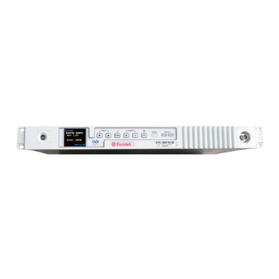
Page 10: Front Panel
(chapter 6, LEDs and ALARMS) Yellow LED (STORED), for alarms stored indication. (chapter 6, LEDs and ALARMS) I/O connector (BNC). Code and serial number label. Escape key. Modifying variable keys. Eurotek label. Explorer menu and display mode keys. EK-MFR/2 25/02/2016 Arch.5105 601-000147/MN Rev. Y... -
Page 11: Rear Panel
3. R ANEL ANEL VIEW EAR PANEL DESCRIPTION Slot 0. Slot 1. Slot 2. EK-PWS/X* panel. Slot 5. Slot 4 Slot 3 Additional ground connection * The different power supplies solutions are described in the EK-PWS/x, EK-PWS/A and EK- PWS/D manual. 601-000147 Rev. -
Page 12: Display And Keyboard
When the general switch (par. 2.2, front panel description) is turned on, the booting of the system is running. At the end of the booting the EK-MFR/2 display shows, the following configuration: Pressing the “enter” key (par. 2.2, front panel description), it is possible to start the insertion password operations (if the user, after the booting, press the “enter”... - Page 13 The RW letters appear, in the figure above, near the key symbol; this indicates that the actual active password allows to read and modify the value of the variables in every board inserted in EK-MFR/2. If any of the boards is not inserted in a particular slot of the EK-MFR/2, the display shows the following situation: 601-000147 Rev.
-
Page 14: Ek-Mfr/2 Menu
5. EK-MFR/2 M ENU REPRESENTATION The complete EK-MFR/2 menu is described below. Variable name Variable number Main EK-MFR/2 >Passwords >>r/o PWD >>r/w PWD >Power Loops >>Loop 1 >>>Enable 1 >>>Source 1 >>>Target 1 >>>P Goal 1 >>>P Source 1 >>Loop 2 >>>Enable 2... -
Page 15: Menu Description And Keyboard Guide
>>Relay 4 >Clock Set >>Year >>Month >>Day >>Hour >>Minute >Network >>IP mode >>IP address >>IP netmask >>GW address ENU DESCRIPTION AND KEYBOARD GUIDE La descrizione di ogni singolo menu dell' EK-MFR/2 è di seguito riportata: 601-000147 Rev. Y Arch. 5105 25/02/2016... - Page 16 The Passwords menu allows to modify the reading only and the reading/writing password. To do this, the user must digit the password provided by the Eurotek, when the general switch (par. 2.2, front panel description) is turned on and the booting of the system is complete (par 4.1 display and keyboard description).
- Page 17 Indoor version and Outdoor version set-up instructions. Indoor version An Indoor version is basically composed by: EK-MFR/2 EK-UCM/x (where '/x' = band of the Up Converter, e.g. UCM/10 = Up Converter in 10 GHz Band, see 'EK-UCM/X' User's Handbook).
- Page 18 Tabella 5.1: : Indoor version Set-up Table EK-MFR/2 25/02/2016 Arch.5105 601-000147/MN Rev. Y...
- Page 19 We analyze the setting of every single menu of the Power Loops supposing of working with the QPSK modulations to obtain a back-off of 4 dB relating the saturate power (0 db) of the Amplifier (EK-AMP/1) inserted in EK-MFR/2. In this case, with reference to the table 5.1, the following values have to be set: EK-MFR/2 >>Loop...
- Page 20 (classified in the table as EK-UCT/na). Power supply version In according with the power supply model loaded in the EK-MFR/2 Source and EK-MFR/2 target it is possible to obatin the following variable combination for the Power Loop Source variable:...
- Page 21 Vin1 EK-PWS/12 The power out value of the AMP loaded in the EK-MFR/2 Source in converted in the analog voltage Vout0. The Vout0 is present on the EK-PWS/A 15 poles connector (see APPENDIX F). This analog voltage is carried out on the EK-PWS/12 loaded in the EK-MFR/2 target by an external cable connection.
- Page 22 Next image shows the setting of the Source variable to the PWS0 3V value using the remote menu eurotek software. EK-MFR/2 25/02/2016 Arch.5105 601-000147/MN Rev. Y...
- Page 23 Tabella 5.2: Outdoor version Set-up Table The next example explains how to set the Power Loops for a typical Outdoor version. 601-000147 Rev. Y Arch. 5105 25/02/2016...
- Page 24 QPSK modulations to obtain a back-off of 4 db relating the saturate power (0 db) of the transmitter SHF connected to EK-MFR/2 by the EK-CDP/1 board. In this case, with reference to the table 5.2, the following values have to be set: EK-MFR/2 >>Loop...
- Page 25 Power loop configuration example Power Loop Configuration With EK-AMH/6 EK-PWS/X----> EK-PWS/X 601-000147 Rev. Y Arch. 5105 25/02/2016...
- Page 26 Power Loop Configuration With EK-AMH/6EK- PWS/X----> EK-PSI EK-MFR/2 25/02/2016 Arch.5105 601-000147/MN Rev. Y...
- Page 27 Power Loop Configuration With EK-AMH/6 EK-PSI----> EK-PSI NOTE: the pin 6 of the EK-PSI/1 15 poles connector must be set on the Vout 0 (see 15 poles expansion connector section) 601-000147 Rev. Y Arch. 5105 25/02/2016...
- Page 28 Power Loop Configuration With EK-AMH/6 EK-PSI----> EK-PWS/X NOTE: the pin 6 of the EK-PSI/1 15 poles connector must be set on the Vout 0 (see 15 poles expansion connector section) EK-MFR/2 25/02/2016 Arch.5105 601-000147/MN Rev. Y...
- Page 29 Config0 recalling and a 6 second countdown starts. At the end of the 6 seconds the Config0 is recalled and active on the EK-MFR/2. If the key is released before the end of the 6 second, the Config0 is not recalled.
- Page 30 2,10,20, 30 or 360 minute. >>SCI 2: Allows to switch on and off the secondary serial interface. >>Ext Power Allows to read the value of the power of the external analog Eurotek unit connected to the EK-MFR/2 by the expansion connector. EK-MFR/2 25/02/2016...
- Page 31 Condition Builder software application manages the parameters of the boards inserted in the Slave EK-MFR/2. The Master, in real time, monitors the status of the Slave in order to obtain the correct switch in case of failure, the state of the Slave is read on ADO input of the power supply unit.
- Page 32 The Clock Set menu allows to set the parameters of the internal time system. Through the “explorer menu” keys (par. 2.2, front panel description) it is possible to set the five sub-menus below. >>Year >>Month EK-MFR/2 25/02/2016 Arch.5105 601-000147/MN Rev. Y...
-
Page 33: Temperature Control
ED DESCRIPTION On (green light) : indicates that the EK-MFR/2 is active. The light is always on also if the display and the keys are off (if the user has to set the time to exit in the Miscellaneous menu of the EK-MFR/2). -
Page 34: Alarms Description
It is possible that more alarms are simultaneously present; in this case the alarms are showed on the same row on the display every two seconds. This function allows to have a general information of the alarms without to explore the menu of every used slot. EK-MFR/2 25/02/2016 Arch.5105 601-000147/MN Rev. Y... -
Page 35: Operating System
PERATING SYSTEM PERATING SYSTEM CONNECTION It is possible to connect the EK-MFR/2 with a terminal unit to use the RS232 interface (to see the rs232 interface settings in the Appendix C) or the Ethernet 10/100 Base T interface. The connectors, of these interfaces, are visible in the chapter 3 “rear panel”. -
Page 36: Erase_Log
Enter the new password (minimum of 5, maximum of 8 characters) Please use a combination of upper and lower case letters and numbers. Enter new password:hello12 Bad password: too simple. passwd: The password for super_user is unchanged. EK-MFR/2 25/02/2016 Arch.5105 601-000147/MN Rev. Y... -
Page 37: 7.2.4 Exit
The first operation to execute is the insertion of the old password value, subsequently is required to enter the new password value. WARNING: the password value must be a combination of upper and lower case letters and number (minimum of 5 and maximum of 8 characters). In the example above, the “hello12”... -
Page 38: Air Flow Consideration
The web pages allows to read and modify the variables of every slot inserted in the EK-MFR/2 unit. To do this, it is necessary to connect the EK-MFR/2 with a terminal unit (PC), by the Ethernet 10/100 Base T interface. - Page 39 : admin The password value is : admin. admin When the user name and the password values are inserted, pushing on the OK window it is possible to enter in the EK-MFR/2 main web page. 601-000147 Rev. Y Arch. 5105 25/02/2016...
-
Page 40: Ek-Mfr/2 Electrical Interface
EK-MFR/2 ELECTRICAL INTERFACE The following table shows the electrical connections of the EK-MFR/2. Every slot is electrically interfaced with the EK-MFR/2 signal present in the table below. The matrix configuration software allows to set the the high speed data signals (A column), so it is possible to obtain the transit of a signal from a board to another one. -
Page 41: Appendix B
The label RESET indicates that the RESET signal is active low. APPENDIX B RS-232 SETTINGS To connect the EK-MFR/2 to a terminal unit by the RS232 interface, is necessary to set the following value of the COM port parameter: 115200 bauds... -
Page 42: Rs-232 Settings
APPENDIX C CONNECTION INTERNAL VERSION (for up and down converters pourpose) EXTERNAL VERSION (for EK-CDP insertion on slot 3) EXTERNAL VERSION (for EK-CDP insertion on slot 0) EK-MFR/2 25/02/2016 Arch.5105 601-000147/MN Rev. Y... -
Page 43: Snmp - Virtual Slot
SNMP – V IRTUAL SLOT The EK-MFR/2 snmp-server default operation mode uses "Octect String" data types. In this mode you can set and get any variable using SNMP string types. In order to use integer types too, you have to point to a "virtual slot" (named "NEW OID" in the configuration file) that maps new, virtual oid into the real oid. - Page 44 SnmpVirtualSlotDataBase Table 1 - fields EK-MFR/2 25/02/2016 Arch.5105 601-000147/MN Rev. Y...
- Page 45 IP TRAP DEST This is the IP address the trap will be sent to. This is the number specified after the enterprise number (19222 for Eurotek) in the OID that will be sent for the trap. TRAP GROUP TRAP NUMBER This is the specific trap number that will be sent for the trap;...
-
Page 46: Ek-Mfr/2 Power Supply Solutions
The breaker must always be installed in a position that is easily accessible. The EK-MFR/2 can be equipped with different power supply configurations. 110 Vac 220 Vac / 18 Vdc 36 Vdc (see EK-PWS/x user’s handbook) -
Page 47: Example Of Module Extraction
A feature of the EK-PWS/A, EK-PWS/C e EK-PWS/D power supply modules is the easy replacement of the unit without the service break (hot-swap) Next image shows a detail of the EK-MFR/2 with two EK-PWS/D loaded. 601-000147 Rev. Y Arch. 5105... - Page 48 The insertion of the power supply module must be done pushing the untit in the apposite slot until the handle locking The extraction procedures valid for the EK-PWS/D are valid for the EK-PWS/C and the EK- PWS/A also. WARNING EK-MFR/2 25/02/2016 Arch.5105 601-000147/MN Rev. Y...
-
Page 49: Ek-Pws/A, Ek-Pws/Ceek-Pws/Dpower Supply Interface (Ek-Psi/1)
EK-PWS/D (EK-PSI/1). POWER SUPPLY INTERFACE The EK-PSI/1 is the power supply interface of the EK-MFR/2 system. This unit allows the electrical and mechanical connections between the power supply unit (EK-PWS/A, EK-PWS/C and EK- PWS/D) and the EK-MFR/2. At the 15 contacts connector are connected the relays and the RS-232 interfaces plus +12V supply for low power pourpose. - Page 50 The figure below displays an EK-MFR/2 unit. On the back of the EK-MFR/2 is located the power supply section. Power supply section The power supply section is composed by the power supply interface and, in this example, by one EK-PSW/A (see EK-PSW/A user handbook) and one EK-PWS/D (see EK-PSW/A user handbook).
-
Page 51: Poles Expansion Connector
The power supply interface panel is composed by a 15 contact connector (A), a RJ45 connector (B) and the steel locking knobs (C). POLES EXPANSION CONNECTOR The pinout of the expansion connector with the relative pin funcion are reported below PIN NUMBER PIN FUNCTION UART 2 TX RELAY E (Relay 0) - Page 52 *On the pin 5,6 and 7 it is possible to select which signal must be set using the switch located on the EK-PSI/1. (next figure) Pos. Right Pos. Right Pos. Left Pos. Left Pos. Right Pos. Left Relay B Vout3 Relay F Vout1 Relay D Vout0 EK-MFR/2 25/02/2016 Arch.5105 601-000147/MN Rev. Y...
-
Page 53: Connector
RJ-45 CONNECTOR PIN NUMBER PIN FUNCTION TX + TX - 8 7 6 RX + RX - 601-000147 Rev. Y Arch. 5105 25/02/2016... -
Page 54: Ek-Psi/1 Insertion /Deinsertion Procedure
NSERTION INSERTION PROCEDURE The EK-MFR/2 is supplied with the EK-PSI already inserted in the module. To be an may need to replace the power supply solution, for example the EK-PWS/11 or EK-PWS/12 or EK-PWS/13 with the EK-PWS/A. In this case it is necessary to extract the EK-PWS/1x and to insert the EK-PSI/1 first and then the new power supply solution. -
Page 55: Appendix G
APPENDIX G Next image reported the EK-MFR/2 fan interface view. It is composed by the two fan located in the apposite mechanical support. Fan Support 601-000147 Rev. Y Arch. 5105 25/02/2016... -
Page 56: Fans Technical Specification
ANS TECHNICAL SPECIFICATION Parameter Value Supply voltage [Vdc] Current consumption [mA] Power consumption [W] 1.38 Speed [RPM] 8200 Air flow [CFM] 10.8 Noise [dBA] 27.5 EK-MFR/2 25/02/2016 Arch.5105 601-000147/MN Rev. Y... -
Page 57: Replacement Fan Procedure
EPLACEMENT FAN PROCEDURE A very important feature of the EK-FAI/1 module is the easily extraction in case of a damage The above image shows an EK-MFR/2 unit with the EK-PWS/D double power supply. To remove the fan interface, it is necessary ... -
Page 58: Hsb Master / Slave Wiring Connections
HSB MASTER SLAVE WIRING CONNECTIONS In according with the HSB menu explained in the EK-MFR/2 menu section, the above figures shows the electrical connection that must be done to obtain an HSB standard application . WARNING: WHEN, IN THE HSB SYSTEM IS PRESENT THE EK-PWS/x, IT IS NECESSARY... - Page 59 HSB System with: EK-MFR/2 unit power supplied by EK-PWS/A or EK-PWS/D (Master) EK-MFR/2 unit power supplied by EK-PWS/x (Slave) External relay N.B. IN CASE OF EK-SWO/x PRESENCE (INSTEAD OF THE RELAY) THE "1+1" IS CONTROLLED BY THE CONDITION BUILDER SOFTWARE (“On Air” parameter) 601-000147 Rev.
- Page 60 HSB System with: EK-MFR/2 unit power supplied by EK-PWS/x (Master) EK-MFR/2 unit power supplied by EK-PWS/A or EK-PWS/D (Slave) External relay N.B. IN CASE OF EK-SWO/x PRESENCE (INSTEAD OF THE RELAY) THE "1+1" IS CONTROLLED BY THE CONDITION BUILDER SOFTWARE (“On Air” parameter)
- Page 61 HSB System with: EK-MFR/2 unit power supplied by EK-PWS/x (Master and Slave External relay N.B. IN CASE OF EK-SWO/x PRESENCE (INSTEAD OF THE RELAY) THE "1+1" IS CONTROLLED BY THE CONDITION BUILDER SOFTWARE (“On Air” parameter) 601-000147 Rev. Y Arch.
- Page 62 HSB System with: EK-MFR/2 unit power supplied by EK-PWS/A or EK-PWS/D (Master) External unit (Slave) External relay N.B. IN CASE OF EK-SWO/x PRESENCE (INSTEAD OF THE RELAY) THE "1+1" IS CONTROLLED BY THE CONDITION BUILDER SOFTWARE (“On Air” parameter)
- Page 63 HSB System with: EK-MFR/2 unit power supplied by EK-PWS/x (Master) External unit (Slave) External relay N.B. IN CASE OF EK-SWO/x PRESENCE (INSTEAD OF THE RELAY) THE "1+1" IS CONTROLLED BY THE CONDITION BUILDER SOFTWARE (“On Air” parameter) 601-000147 Rev.
- Page 64 HSB System with: EK-MFR/2 unit power supplied by EK-PWS/x (Master) EK-MFR/2 + EK-AMH/6 unit power supplied by EK-PWS/x (Master) EK-MFR/2 unit power supplied by EK-PWS/x (Slave) EK-MFR/2 + EK-AMH/6 unit power supplied by EK-PWS/x (Slave) External relay N.B.
- Page 65 Eurotek S.r.l. c/o Parco Scientifico Tecnologico e delle Telecomunicazioni in Valle Scrivia Strada Comunale Savonesa, 9 15057 RIVALTA SCRIVIA (AL) ITALY tel. +39 (0)131 860205 r.a. fax +39 (0)131 860993 http://www.eurotektel.com e-mail: info@eurotektel.com 601-000147 Rev. Y Arch. 5105 25/02/2016...
- Page 66 EK-MFR/2 25/02/2016 Arch.5105 601-000147/MN Rev. Y...
Need help?
Do you have a question about the EK-MFR/2 and is the answer not in the manual?
Questions and answers