
Related Manuals for Nanomotion XCDX

Summary of Contents for Nanomotion XCDX
- Page 1 User Manual XCDX Four Axis Controller/Driver XCDX458000-00 rev A June 2, 2016 Nanomotion Ltd. POB 623, Yokneam 20692, Israel Tel: 972-73-2498000 Fax: 972-73-2498099 Web Site: www.nanomotion.com E-mail: nano@nanomotion.com...
- Page 2 XCDX458000-00 rev A...
- Page 3 Limited Warranty Nanomotion Ltd. (hereinafter NM) warrants the product (other than software) manufactured by it to be free from defects in material and workmanship for a period of time of one year (except those parts normally considered as consumable/expendable components such as motor conditioning brushes).
- Page 4 NM products. Without limiting the generality of the preceding sentence, NM shall not be liable to the Purchaser for personal injury or property damages. Patents Nanomotion products are covered under one or more of the following registered or applied for patents. 5,453,653; 5,616,980; 5,714,833; 111597; 5,640,063; 6,247,338; 6,244,076; 6,747,391;...
- Page 5 Revision History The following table shows the last three revisions to this document. Date Description May 2016 Release XCDX458000-00 rev A...
-
Page 6: Table Of Contents
Electrical Connections..........21 Operating the XCDX Controller/Driver ........22 System Setup . - Page 7 Programming the XCDX Controller/Driver ......56 Programming the XCDX MCU and the XCD-HR MCUs ......56 PREPARE THE UPGRADE.
-
Page 8: Introduction
• Programming the XCDX Controller/Driver on page 56 The XCDX Box contains two firmware and software programs. The XCD-HR™ and EDGE™ Controller/Drivers are programmed with XCD Motion Script™ (XMS). for detailed information about this firmware refer to the latest XCD Firmware user manual. -
Page 9: Related
Danger: Indicates operations or activities that may cause damage to equipment or injury to personnel. ELATED The following table lists Nanomotion products which may have this software version. Refer to your user manual to verify installed software version. Product Part Number XCD HR1™... -
Page 10: Overview & Specification
& S VERVIEW PECIFICATION The XCDX motherboard has an FPGA and MCU that provide control of up to four axes with any of the following motors: • EDGE • • • • • HR16MCU Control of the axes is by open loop control from the XCDX Commander, an external joystick, or a XMS program saved to each of the XCD Controller/ Drivers. -
Page 11: Front And Rear Panel Layout
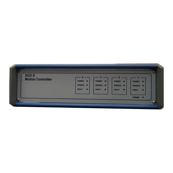
Specifications 2.1.1 RONT AND ANEL AYOUT The XCDX front panel has LEDs to indicate the status of the XCDX box and each of the installed axes. Figure 1: Front Panel • XCDX Power - power to the XCDX box •... -
Page 12: Power
Table 5 2.1.2 OWER The XCDX Controller/Driver is factory configured for either AC or DC power based on customer request. The XCDX Box meets EMI/RFI compatibility according to CE class B. The front panel has LED power indicators for the XCDX Box and the XCD Controller//Driver for each configured axis. -
Page 13: Motor Interface
They must be shorted together on the plug connected to the motor 2.1.4 NCODER NTERFACE The XCDX Controller/Driver supports up to 4 digital Differential encoders (Renishaw), each encoder corresponding to specific axis and XCD-HR Controller/Driver connected. When configured with XCD-EDGE Controller/ Drivers, only single-ended encoders are supported. -
Page 14: I/O Connectors
Specifications Table 3: Encoder Connector Pinout Output Function Signal Type Alarm Set-up inner shield connection Shield outer shield case The Limits, Alarm, and Set-up signals are not connected Are these still not enabled? 2.1.5 I/O C ONNECTORS The back panel has two 37 pin connectors to provide monitoring and use of various internal signals including GPIOs. - Page 15 Specifications • Input impedance >7k Analog output • Connected directly to corresponding axis controller • Output voltage range 0-10V • Maximum load 5k (1% voltage drop) Example external power supply 24v+10% Max Table 4: J5A- GPIO, Connector 2 Name Direction Description Voltage GPIO 1...
- Page 16 Specifications Table 4: J5A- GPIO, Connector 2 Name Direction Description Voltage GPIO 8 output Y-Axis PPI digital output TTL 5V GPIO 11 output Y-Axis digital GPIO3 TTL 5V GPIO 12 output X-Axis PPI digital output TTL 5V GPIO 15 output X-Axis digital GPIO3 TTL 5V Pull to...
-
Page 17: Isolated Signals
Do not use INS_IN1 Do not use INS_IN3 Do not use INS_IN5 Do not use 2.1.6 SOLATED SIGNALS The XCDX Box provides internally isolated inputs and ouputs. • Limits • INS - isolated IO inputs • PLD_INS_IN • PLD_INS_OUT Each of the following images shows the isolated circuit. - Page 18 Specifications Figure 4: Limit and EMO Switch Input Connections Figure 5: Isolated Output Connection XCDX458000-00 rev A...
-
Page 19: Digital Triggers
The XCDX Motherboard combines (ORs) the 4 signals to create the output signal. The trigger is programmable (Level, Axis in trigger, Pulse width) Maximum delay from each axis output trigger to the XCDX output trigger is less than 1s. This corresponds to 100ns jitter. -
Page 20: Coordinated Moves
2.1.9 OYSTICK The XCDX can be controlled by a 3 axis 2 button joystick when configured for 3 axis operation. The default setting at power up is joystick. The XCDX SW can lockout the joystick if desired. The joystick interface connector is a mini DIN 8 pin. -
Page 21: Installation And Operation
Each axis is connected to a Nanomotion XCD™ or Figure 1, page 22). For closed-loop operation an EDGE™ motor (refer to encoder can be connected from the stage axis back to the XCDX box. XCDX458000-00 rev A... -
Page 22: Operating The Xcdx Controller/Driver
PERATING THE ONTROLLER RIVER The XCDX Box can control a stage with up to 4 axes. Control is either through a motion profile saved on the XCD-HR and EDGE Controller/Drivers, or with a joystick that can control up to 3 axes. -
Page 23: System Setup
ETUP 1. Install the XCDX Commander on the host computer. The XCDX Commander and sample test scripts was supplied with the XCDX Box. For additional copies contact your field service representative. Ensure that the Controller/Driver’s power switch is in the off position and connect to the power (AC or DC). - Page 24 Figure 2: XCDX Commander Main Window Communication The Communications panel has two dropdown menus and an INFO field. • Port - selects the port on the host computer connected to the XCDX • Address - Selects which subassembly in the XCDX Box to communicate with.
-
Page 25: Xcdx Test Panel
Flash must be done with a direct link between the host computer and the XCDX box. • XCDX Test - refer to the XCDX Test Panel section below Command Interface Provides the ability to send individual commands or read variable parameters from the selected XCD Controller/Driver or the motherboard. - Page 26 Operating the XCDX Controller/Driver • Kill - aborts current stage operation. • Set Trigger Polarity - options are Active High and Active Low. • Joystick Enable - enables the joystick. Before selecting and sending this function, set the Init Joystick center option.
-
Page 27: Raster Tab
Operating the XCDX Controller/Driver 3.2.3.2 ASTER TAB The Raster data must be sent before selecting and sending Raster mode selected. • Raster Mode - provides selection of any of four modes: Start, Pause, Resume, Abort, Send/Repeat. • Raster Data - provides selection of parameters for the Raster. -
Page 28: Log Settings
Operating the XCDX Controller/Driver Figure 4: Raster Tab 3.2.3.3 ETTINGS The Log Settings tab is used for integration only. • - deletes data in lower field LEAR • Command 26 reply determines the display format. (Binary and Float are not operational) - Page 29 Operating the XCDX Controller/Driver Figure 5: Log Settings Tab XCDX458000-00 rev A...
-
Page 30: Joystick
Operating the XCDX Controller/Driver 3.2.3.4 OYSTICK The three fields read the voltage on each axis of the joystick Figure 6: Joystick Tab 3.2.3.5 LASH • IP Address (refer to Ethernet Protocol, page • Net Mask • License • Active XCDs This function is set at the factory. - Page 31 Operating the XCDX Controller/Driver Figure 7: Flash Tab By default X, Y, Z are active. It can be modified from the commander under the Flash tab: • 0 = All LEDs are off • 1 = X is active •...
-
Page 32: Upgrade
Operating the XCDX Controller/Driver 3.2.3.6 PGRADE The Upgrade tab allows running the upgrade script directly from the XCDX Programming the XCDX Controller/Driver, Commander. Refer to page 56 for details of preparing the upgrade script. Figure 8: Upgrade Tab 3.2.3.7 LASH The Flash pane provides random access to the 128KB storage for free entry data. - Page 33 Operating the XCDX Controller/Driver Figure 9: User Flash XCDX458000-00 rev A...
-
Page 34: Xcdx Communications Protocol
User Manual for full specification. The total length of the commands should not exceed 50 bytes. Commands sent to channel 128 (0x80) are extended commands executed in MCU; see XCDX Commands for details. The total length of the commands is up to 80 bytes. XCDX458000-00 rev A... -
Page 35: Communication Protocol
The controller sends reply; in many cases, the reply is simply a prompt, which reports whether the command is accepted or rejected. Each host command consists of the following parts: Table 1: XCDX Host Command Format Byte Size in Part... -
Page 36: General Usb Protocol
4.3.2 THERNET ROTOCOL Each XCDX box has its own 4-byte IP address. In a dotted form, IP address consists of four numbers, like 172.21.234.168. The XCDX box determines its IP address at start up, and then accepts only commands sent to this address, or broadcasted commands. -
Page 37: Udp Ports
0x1E27 (7719) is used for receiving Discover command 4.3.5 OMMAND AND REPLY STRUCTURE XCDX Ethernet protocol is based on UDP protocol. Each message sent to the XCDX and from XCDX is a UDP datagram complying with IPv4 standard. Figure 1: UDP Protocol UDP header should specify destination port 0x1745 (5957). - Page 38 Communication Protocol Figure 2: UDP Command Structure Similarly, one reply UDP datagram can comprise one or more XCDX replies (number in parenthesis specifies the field size in bytes): Figure 3: UDP Reply Structure XCDX458000-00 rev A...
- Page 39 Communication Protocol Numbers in XCDX command and reply block are sent in little-endian format, i.e. the least significant byte first. Each XCDX command block consists of the following parts: Table 3: XCDX command Block Byte Size in Part Description offset...
-
Page 40: Discovery Protocol
4.3.5.1 ISCOVERY PROTOCOL Discovery protocol is used to find out one or more XCDX boxes connected to a PC or to network segment. Unlike other XCDX commands, Discover command is sent with broadcast IP address; each node in the LAN segment receives the command. The XCDX responds to Discovery command submitting to the host its IP address. -
Page 41: Data Types
UDP port from the Discover message and responds to this address/port with UDP message. The payload of the reply is not specified; the Host uses only source IP address of the message to find out the XCDX IP address. -
Page 42: Add Vectors
Count1 X1 Real(4) Count2 X2…. Int32(4) Real (4) 4.5.3 ERSION Request MCU Firmware version. The XCDX reply contains 10-byte Extension structured as follows: • Bytes 0-3: four bytes of Firmware version • Bytes 4-7: four bytes of Serial number •... -
Page 43: Get Ip
Int8(1) License Int8(0º59) 4.5.7 ICENSE Get License data. The XCDX returns License data stored in the flash memory. Extension field of the XCDX reply contains up to 60 bytes of the License data. Command ID Parameters Format XCDX458000-00 rev A... -
Page 44: Get Ip
Format 4.5.10 Initiate a Homing operation for all selected axes. All parameters are optional. XCDX stores internal table of default parameters for each axis. Therefore, if no parameters are specified XCDX executes homing process specific for each selected axis. However, if a parameter is specified, it replaces the default value for all selected axes. -
Page 45: Get Status
XCDX Commands 4.5.11 TATUS Request XCDX status. The XCDX reply contains 28-byte Extension field structured as follows: • Bytes 0-3:bitwise MCU state: • Bit 0: X axis power; 1 - powered, 0 - not powered • Bit 1: Y axis power; 1 - powered, 0 - not powered •... -
Page 46: Kill
XCDX Commands • T (optional): defines T value. If omitted, T is set to zero in the current point. Command ID Parameters Format Selector (opt) Int8(1) X (opt) Real(4) Y (opt) Real(4) Z (opt) Real (4) T (opt) Real (4) 4.5.13... -
Page 47: Center Joystick
Command ID Parameters Format Selector Int8(1) (opt) 4.5.17 ASTER Set Raster data. The command prepares XCDX for raster motion. Refer to Raster operation, page 49 for more information. Command ID Parameters Format Options Int32(4) Count Int32(4) -
Page 48: Raster Mode
XCDX Commands 4.5.18 ASTER Set Raster mode. The command sets raster mode. Parameter Mode can specify one of the following values: 1 - Run 2 - Pause; the motion stops at the end of current vector and waits for the next command 3 - Resume;... -
Page 49: Write User Flash
Special Operations • number of bytes to read, from 2 to 60, even values only Command ID Parameters Format Int8 (1) offset Int32(4) count Int32(4) 4.5.21 RITE LASH The controller writes the specified bytes to user flash. • ID of the user flash (should be 1), •... -
Page 50: Raster Data
Raster operation: Figure 4: Raster Operation Flow Chart To initiate Raster operation, first send to XCDX Raster Data command. In case of non-rectangular raster, the Raster Data command must be followed with a set of Add Vectors commands to specify individual vectors. To start physical operation, send Raster Mode command with parameter 1 (Run). - Page 51 The distance is added to the beginning and to the end of each vector. The addition is required to provide triggering Overrun Real (4) at constant velocity. If the parameter is zero, XCDX automatically calculates the distance using Velocity and Acceleration parameters. XCDX458000-00 rev A...
-
Page 52: Rectangular Raster
Special Operations Table 6: Raster Data Commands Parameters Parameter Format Comments Dwell in milliseconds in a trigger point. The parameter is only used in Step-repeat Dwell Real (4) operation; in normal operation, the parameter is ignored. Pulse Width Real (4) Width of trigger pulse in milliseconds. -
Page 53: Non-Rectangular Raster
The operation continues until the end of the current vector, and only then stops. This way, all trigger points are processed at required velocity. Then XCDX holds XY position until the next Raster Mode command; further operation depends on the Raster Mode parameter: •... -
Page 54: Step-Repeat Operation
Example Scripts If raster motion is started by Raster Mode with parameter 5 (Single vector), the motion stops at the end of the vector and waits for the next Raster Mode command as described above. 4.6.6 EPEAT PERATION Raster Mode command with parameter 9 starts raster operation in a Step- repeat mode. - Page 55 Example Scripts // wait additional 25 msec for 10Hz delay 25 // Toggle IO_2 if IO_2 IO_2 = 0 else IO_2 = 1 XCDX458000-00 rev A...
-
Page 56: Programming The Xcdx Controller/Driver
, or : that defines the target within the XCDX box. This is followed by one or more file names separated by space(s). The file names define the binary files to be programmed into the target defined at the beginning of the line. Specify the file... -
Page 57: Programming The Xcdx Mcu And The Xcd-Hr Mcus
:MCU XCDX.HEX // Upgrade MCU to v.1.1.1.2 5.1.3 TO EXECUTE UPGRADE: 1. Copy the upgrade directory (see above) to your PC. 2. Launch the XCDX Commander and establish communication with XCDX box. 3. Select XCDX T , and select UPGRADE tab. - Page 58 NDEX analog I/O get limits ..........25 examples get status ........14 ..........25 closed-loop init joystick center ..........21 .......26 command input add vector analog ........42 ..........14 center joystick Installation .......47 ...........23 get IP IO connector ..........43 ........14 get license IO connector 1 ........43 get status output...
- Page 59 NDEX XCDX Commander ............19 .......23 XCDX controller reply format ....35 XCDX host command format ....35 XCDX Test Panel ........23 XCDX test panel raster commands tab .......25 non-rectangular ......53 command 26 reply rectangular ..28 ........52...
- Page 60 NDEX XCDX458000-00 rev A...
Need help?
Do you have a question about the XCDX and is the answer not in the manual?
Questions and answers