Advertisement
Quick Links
Advertisement

Related Manuals for EA4TX RemoteBox Series

Summary of Contents for EA4TX RemoteBox Series
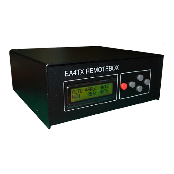
- Page 1 RemoteBox RemoteBox Hardware Reference & Operational Manual Feb/2019 Rev 1.7a ENG...
- Page 2 Introduction The RemoteBox family of controllers is comprised of several universal antenna switching controllers. There are 6 models based on the number of inputs and number of antennas it can control. These are the available models: • RemoteBox 4-Square (4 Square antennas) •...
- Page 3 Please read carefully the manual prior to making any connections. If any issue or problem arises from the use of this device please do not hesitate to contact the manufacturer at: Address: Definit Data SL Att: Mr. Pablo García - EA4TX Fresno 67 28522 Rivas Madrid - SPAIN E-mail: sales@definitdata.com...
-
Page 4: Important Notice
IMPORTANT NOTICE READ BEFORE OPERATING THIS UNIT PRECAUTIONS ! – THIS UNIT IS NOT A TOY. IT MUST NOT BE HANDLED BY CHILDREN NOR PLACED/OPERATED WITHIN REACH OF CHILDREN. ! – DO NOT LEAVE PACKING MATERIAL FOR THIS UNIT UNATTENDED. IT MAY BE HARMFUL TO CHILDREN IF MISUSED. -
Page 5: Legal Notices
LEGAL NOTICES © 2018 Definit Data. All rights reserved. RemoteBox®, RMB, EA4TX and related trademarks, names, and logos are the property of Definit Data and are registered and/or used in SPAIN and countries around the world. All other trademarks are the property of their respective owners. - Page 6 DAMAGES: DIRECT, CONSEQUENTIAL, EXEMPLARY, INCIDENTAL, INDIRECT, SPECIAL, PUNITIVE, OR AGGRAVATED DAMAGES, DAMAGES FOR LOSS OF PROFITS OR REVENUES, FAILURE TO REALIZE ANY EXPECTED SAVINGS, BUSINESS INTERRUPTION, LOSS OF BUSINESS INFORMATION, LOSS OF BUSINESS OPPORTUNITY, OR CORRUPTION OR LOSS OF DATA, FAILURES TO TRANSMIT OR RECEIVE ANY DATA, PROBLEMS ASSOCIATED WITH ANY APPLICATIONS USED IN CONJUNCTION WITH DEFINIT DATA PRODUCTS OR SERVICES, DOWNTIME COSTS, LOSS OF THE USE OF DEFINIT DATA...
-
Page 7: Copyright Information
PORTIONS OF ANY DEFINIT DATA PRODUCT OR SERVICE OTHER THAN THIS DOCUMENTATION. COPYRIGHT INFORMATION Copyright © 2018 Definit Data All rights reserved Information in this document is subject to change without notice and does not represent a commitment on the behalf of Definit Data. No part of this publication may be reproduced, stored in a retrieval system, or transmitted in any form or by any means, electronic, mechanical, photocopying, recording or otherwise, for any purpose other than the purchaser’s personal use, without the prior express written... - Page 8 Section 1 RemoteBox Hardware RemoteBox has the following connections: • 12-14Vcc power cable. • Antenna switch connector: Ant1 or Ant2 (based on model) • Band Data Input 1 or 2 Radios (based on model). • Auxiliary Interface (i.e. band Pass Filter control) or Antenna 9-12 output •...
- Page 9 Pin-3: “C” Output It’s simple to know that this special firmware is used by the firmware during the startup sequence of the unit. It’s displayed at the LCD a message as: EA4TX RB1x8 BCD Page 9 Hardware Reference and Operational Manual: RemoteBox...
-
Page 10: Important Note
4 Square Version: The RemoteBox 4-Square model uses 3 pins of the ANT1 output (plus ground). Generating different values on those pins, it can command the TK5EP phased switch ANT1/2/6 and 2 signals and ground are used to select the antenna direction. This output is available at: •... - Page 11 1.2 BD1/BD2 Ports: Radio Band Data connection You can use the Band Data input with a Yaesu or Elecraft K3 transceiver; also ICOM Band Voltage input is supported. RemoteBox will receive Band Data and will allow for automation of antenna selection based on band information. This adds practicality and error proofs the radio shack.
- Page 12 1.3 AUX Port: Auxiliary port This auxiliary port allows the control of Band Pass filters such as ICE 419 type (or similar). When RemoteBox senses Band Data information in the Band Data ports it will automatically activate a signal in the DB15 female port to activate the appropriate filter.
- Page 13 Section 2 Configuration Programming the RemoteBox is easy. To access the different configuration menus press the RED button on the front of the device. The RemoteBox will go into programming mode showing the following subset of screens. • Next menu, press the ⇧button (Up arrow). •...
- Page 14 SET3: Priority We can select the default Radio when both Radios select de same Band. Only one antenna can be connected to one Radio (Radio A or B) so this option will define which Radio has priority on the antenna in case of a conflict. These are the available options: •...
- Page 15 Section 3 Operation Operating the RemoteBox is very straight forward. The device has a 2 line by 16 character LCD display. For models “2x” models each radio output (Radio A and B) will present the following information: Antenna Selection M ode Antenna Selected F ocus active Antenna Nam e...
- Page 16 IMPORTANT NOTE: Even with automatic (AUTO) mode enabled we can manually change the antenna without changing to manual (MAN) mode. The manually selected antenna will remain until the device detects a band change through the Band Data port or through the ICOM voltage change.
- Page 17 RemoteBox 4-Square version This special RemoteBox version will display 4 directions at the LCD • Radio Status: If the PTT is connected to the radio and it’s enabled (SET1) the RB will monitor the Radio PTT. At this area a “TX” could be displayed when the Radio is in TX.
- Page 18 Section 4 RemoteBox Manager We can use this program (RBM) in addition of the manual and automatic modes of the RemoteBox. This software will require the use of a computer and the USB port. We can also use the software to change the antenna labels. The enclosed CD-ROM contains the setup file to install RBM.
- Page 19 4.1: Antenna Operation Antenna operation with RBM is easy and very intuitive. The selected antenna is highlighted in GREEN and the rest are GREY. A “2x” model (2x6 or 2x8) will present two rows of antennas for Radio A and Radio B. To manually activate any antenna all we have to do is to left click on it.
- Page 20 4.3: N1MM Setup In a similar way, the RBM can read N1MM network messages and automatically select the antennas (ANT1 and ANT2 Outputs). In this example RBM will read network messages from the broadcast address from the Station “RUN” & VFO-A for Radio 1 and from the Station “MULTI” & VFO-A for the Radio 2.
- Page 21 • Radio Priority: You can select the priority for the Radios in case you try to select the same antenna in both radios. • PTT Control & Force TX: You can use the PTT to control one of the following options: o Avoid Hot-switching: So the antenna will not be changed when the Radio is in TX.
- Page 22 It can be configured different outputs for Radio A and Radio B. Remember to select the true table for Radio A and then for Radio B. You can use the “Copy A->B” to use the same setting at Radio B as used at Radio A. When it’s used a RemoteBox of 6 antennas, that setup will be fixed to 6 Antennas.
- Page 23 4.3: Antenna Labeling This menu allows the user to label the different antenna ports of a controller. You can even disable a particular antenna port if it not being used. The name of the antenna is limited to 4 characters. Page 23 Hardware Reference and Operational Manual: RemoteBox...
- Page 24 Annex I –Yaesu Band Data Connection Yaesu transceivers (FT1000, FT1000MP, 2000, etc.) have a DIN port similar to the image below: This is the connection diagram between a Yaesu DIN8 Band Data port and the RemoteBox Band Data DB9 Female port. Any transceiver that uses the Yaesu (A,B,C and D) Band Data standard can be connected to the same pins in the female DB9 port of the RemoteBox: Page 24...
- Page 25 Annex II – Elecraft K3 Band Data Connection The Elecraft K3 has a Band Data port in the transceiver labeled ACC. It is a DB15 port that sends 4 band signals called: BAND0, BAND1, BAND2 and BAND3 These 4 signals and the common ground are located in the following pins of the ACC connector: Pin 3: Band1 OUT...
- Page 26 Annex III – Inhibit and PTT signal - Yaesu Yaesu radios (FT1000, FT1000MP, 20000, etc) use a DIN connector like this one: The connection that needs to be made between the RemoteBox interface (DB9) and the DIN connector is as follows: Remember that you need to insert a 10K Ohm resistor between pins 1 and 8 of the connector, as shown in this photo: Page 26...
- Page 27 Annex IV – Inhibit and PTT signal – Elecraft K3 In the K3 we use the ACC connector. The pins used are as follows: Pin1 FSK IN (pullup a +5V) Pin5 Pin7 TX Inhibit Pin10 Key Out The connection that needs to be made between the RemoteBox’s DB9 and the ACC is as follows: Remember that you need to insert a resistor (10K ohm for example) between pins 1 and 7 of the ACC connector.
- Page 28 Annex V – Band Data on ICOM – Band Voltage The RemoteBox can select automatically the antenna if you use the Band Data (Yaesu or Elecraft K3) or Band Voltage (Icom) cable to the Radio. Additionally to enable the software option, there is a jumper that must be set or removed, in order to activate it.
- Page 29 Annex VI– USB (Virtual COM) Driver Install The first time you plug the RemoteBox to a computer through the USB port you will receive a “New Hardware Found” message and the following screen will appear. Windows 10 has default drivers for this hardware and will automatically assign a COM port.
- Page 30 The Drivers are included in the enclosed CD-ROM. Select "Search removable media (floppy, CD-ROM,..), and then click "Next". Once installed Windows will automatically create a Virtual COM port to communicate with the RemoteBox. A Virtual COM port is the simulation of a serial port in software in order to allow a USB port to take its place.
- Page 31 How to change the USB Virtual COM Port number in Windows 1. To change the Port Number of the USB COM Port open Device Manager by clicking Start -> Control Panel -> System (or hold down the "Windows" key and press "Pause-Break") select the Hardware Tab and click the Device Manager button.
- Page 32 2. The USB Serial Port (COMX) is in the Ports section To change the Port number right-click the USB Serial Device and select Properties 3. Select the "Port Settings" Tab and click "Advanced" You do not have to change any parameter. Page 32 Hardware Reference and Operational Manual: RemoteBox...
- Page 33 4. Now you can select the Port Number you like to use. 5. Click OK and close all open Dialogs Windows might not suggest restarting the computer but in some cases it might be necessary to manually restart the operating system. Page 33 Hardware Reference and Operational Manual: RemoteBox...
- Page 34 [This page is intentionally left blank.] Page 34 Hardware Reference and Operational Manual: RemoteBox...
- Page 35 Index Introduction ....................2 About the Manual ..................3 IMPORTANT NOTICE .................. 4 LEGAL NOTICES ..................5 COPYRIGHT INFORMATION ............... 7 RemoteBox Hardware ..................8 PCB inside view and layout for RemoteBox ..........8 1.1 ANT1/ANT2 Ports: Antenna Switch Connection ........8 1.2 BD1/BD2 Ports: Radio Band Data connection ........
Need help?
Do you have a question about the RemoteBox Series and is the answer not in the manual?
Questions and answers