Advertisement
Quick Links
Advertisement

Related Manuals for EA4TX ARS-USB

Summary of Contents for EA4TX ARS-USB
- Page 1 Antenna Rotator System ARS-USB Reference Manual June/2024 Rev 2.1a...
- Page 2 If you don't find your rotor mentioned in the Quick Start Guide, again you should contact us. We will provide assistance to help you successfully connect your rotor to the ARS-USB circuit board. It is certain that no changes will be required in the ARS-USB circuit design.
- Page 3 Another manual, the "Quick Installation Guide" is also supplied. It provides information on connecting your ARS-USB board to many popular rotors. Please be sure to properly install and configure the hardware and software as described in this manual. Once this is completed, you may continue with the “Quick Installation Guide.”...
- Page 4 The ARS-USB has the following connectors: J1: The azimuth antenna rotation is controlled by means of this connector. It is attached to 3 relays on the ARS-USB Board. One of the relays provided (AUX) is able to control a brake.
- Page 5 1.1 Connector J1: Azimuth Relay connections The ARS-USB has two relays to control the Azimuth movement: right (CW) or left (CCW). An additional relay (AUX), located between them may be used to control a brake in rotators requiring a braking function.
- Page 6 B to C E to F H to I Relay OFF Relay ON Right/CW B - A B - C E - D E - F Left/CCW H - G H - I Page 6 EA4TX – ARS-USB Manual – June. 2024...
- Page 7 1.2 Connector J2: Elevation Relay connections In addition to the 3 azimuth relays (see note), the ARS-USB Board includes 2 relays for elevation control if an elevation rotor is present. Relay OFF Relay ON J2-2 to J2-1 J2-2 to J2-3...
- Page 8 J3-1 is the positive terminal. J3-2 is the negative terminal. Note: Although the CPU and some parts of the ARS-USB could be powered from the USB, it requires an external power supply. Some components as the relays requires a 12Vdc. Remember to connect this J3 terminal into a 12-14Vdc power supply.
- Page 9 Therefore, there are 2 LEDs (one for Azimuth and one for Elevation) that are used as end of travel or limit reached. These LEDs that light up when the limit is reached are useful during the calibration process. Page 9 EA4TX – ARS-USB Manual – June. 2024...
- Page 10 Pot is Grounded, you can connect the “V-“ Input at J4 (J4-4 for Azimuth and J4-1 for Elevation) to Ground at J4-3. As the ARS-USB board must obtain the voltage feedback from the external Pot, the two wires that join the control unit with the rotator (the one from the cursor of the potentiometer and the other from the ground or reference) must be connected in parallel with the J4 terminals (J4-4 &...
- Page 11 (-3.6V). Therefore the signal to the ARS-USB board will have to be amplified to avoid losing resolution in the converter. Polarity will also change from negative to positive. The is also accomplished by adjusting the gain at Pot1.
- Page 12 The following illustration shows the correct Rotator + Control Unit + ARS-USB wiring: Potentiometer 500Oh Control Unit ROTATOR < > ARS-USB You can find the two wires by looking at the circuit diagram included with the rotator. Be very careful with the polarity! J4-4 is the negative input or reference connection and J4-5 is the cursor of the potentiometer.
- Page 13 Note: Most rotors are referenced to ground, so J4-1 (V-) and J4-4 (V-) must be wired to J4-3. Note: There are 2 points marked as W1 (Azimuth) and W2 (Elevation) where you can easily make a bridge to connect V- to Ground. Page 13 EA4TX – ARS-USB Manual – June. 2024...
- Page 14 Positive Potentiometer Feedback ──────► J4-5 Negative Potentiometer Feedback ─────► J4-4 If the Negative is referenced to Ground, connect J4-4 to J4-3. Once connected, there is a Pot that can be adjusted for correct input to the ARS-USB ADC input: Azimuth Input Adjustment: ...
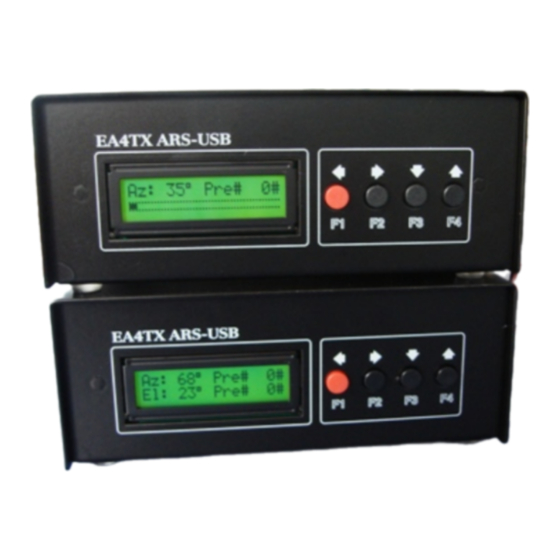
- Page 15 1.7 LCD Socket and contrast adjustment The ARS-USB can handle a 16x2 LCD display. This connector is used to attach the LCD module to the ARS-USB. VR1 can be used to adjust the LCD contrast. This ARS-USB-LCD supports a 16x2 LCD and 4 bush buttons.
- Page 16 1.8 KBD Socket The ARS-USB includes a connector labeled KBD. This allows 4 buttons to be used for manual control of the ARS-USB. There are 4 inputs plus common signal available at the KBD socket. The 5 pins used this IDC (10 pins) are:...
- Page 17 Part 2 Working with the ARS-USB Once you have wired the ARS-USB board with your rotor and the driver is installed, you can begin to control the interface. There are 2 ways you can interact with the product: COM Port: this port is automatically created each time the PC detect the ARS-USB ...
- Page 18 (CCW/Left or CW/Right on Azimuth; Up or Down on Elevation) the relay which control the movement in that direction is disabled. Imagine that the ARS-USB reads ADC = 0, so it suppose that the motor is at the CCW/Left limit. So the CCW Relay will be disabled.
- Page 19 The ARS-USB Unit can show in the LCD, 3 possible errors. Error 1: Az_WD_ALARM Caused when the ARS-USB try to move the Azimuth rotor and after a while, the feedback position is the same (no feedback voltage changed). It could be because the Azimuth rotor is jammed.
- Page 20 Click next to continue. Select Install from Removable Media (Supplied). Click next. The driver is included in the CD-Rom. Once you finish the installation process, a COM Port will be added Page 20 EA4TX – ARS-USB Manual – June. 2024...
- Page 21 COM Port. Any program that needs to communicate with the ARS-USB Board (logger, satellite tracking, etc) needs to use the new this COMx port. Note: You can disconnect and connect the ARS-USB to see which port is assigned by Windows.
- Page 22 5) Click “OK” again. Notice that the device will now appear on the previously unassigned port you just selected. Verify this by closing Device Manager and selecting it again. 6) Close device manager. 7) This process is illustrated on the following page. Page 22 EA4TX – ARS-USB Manual – June. 2024...
- Page 23 Page 23 EA4TX – ARS-USB Manual – June. 2024...
-
Page 24: Specifications
CONNECTOR X1: USB socket. The USB Port is detected by the computer as a COM or Serial port. The ARS-USB emulates a Yaesu GS232S interface, so it’s compatible with any program that supports it. CIRCUIT DIMENSIONS 12cm x 12cm x 3,5cm (Deep, Wide, High) 4.7inch x 4.7inch x .8inch... - Page 25 Notes [The remainder of this page has been left intentionally blank] Page 25 EA4TX – ARS-USB Manual – June. 2024...
- Page 26 B.- Absolute Mode – F2 ......................18 C.- Factory default configuration – F3 + F4 ................18 2.4 Error Messages ..................19 Driver Installation for the ARS-USB ............20 3.1 Port reassignment ................. 22 Specifications ....................24 Notes ......................25 Index ......................
Need help?
Do you have a question about the ARS-USB and is the answer not in the manual?
Questions and answers