Table of Contents
Advertisement
Quick Links
www.ptchronos.com/wecare
User Manual – Automatic Bagging System
OML-1140 – SM16-00032
CP Vietnam Corporation – Hai Duong
© 2016 by Premier Tech Chronos. Right of modification reserved. All rights reserved by Premier Tech Chronos.
Nothing may be reprinted or reproduced without the written consent of the company.
In this technical manual, we give the operator appropriate instructions for the safe and proper operation of the
equipment as well as instructions for the installation and correct maintenance of the equipment. Every person who is
authorized for the transportation, assembly, start up, operation, maintenance, upkeep and repair, as well as
shutdown, of our machines and additional components, is required to have read and understood the instructions in
the individual chapters and sections.
In order to avoid operating error and to guarantee trouble-free operation of our products, this technical manual must
always be available to the operating and maintenance personnel.
___________________________________________________________________________________
Version #1 –October 2016
Advertisement
Table of Contents

Summary of Contents for Premier Tech Chronos OML-1140
- Page 1 OML-1140 – SM16-00032 CP Vietnam Corporation – Hai Duong © 2016 by Premier Tech Chronos. Right of modification reserved. All rights reserved by Premier Tech Chronos. Nothing may be reprinted or reproduced without the written consent of the company. In this technical manual, we give the operator appropriate instructions for the safe and proper operation of the equipment as well as instructions for the installation and correct maintenance of the equipment.
- Page 2 CONTENTS ___________________________________________________________________________________ Version #1 –October 2016...
-
Page 3: Table Of Contents
Contents Page SAFETY WARNINGS AND CHECKS………………………………………………………………………………………………………………… Safety warnings……………………..……………………………………………………………………………………………. Safety lock-out procedure…………………………………………………………………………………………………. Procedure for testing emergency stop functions……………………………………………………………………… GENERAL INFORMATION……………………………………………………………………………………………………………… User information……………………………………………………………………………………………………….. Usage according to the intended purpose……………………………………………………………………………… Required training courses………………………….…………………………………………………………….. 18 TECHNICAL DESCRIPTION….…………………………………………………………………………………………… Main components parts…….……………………………………………………………………………………………… Illustrations…………………………………………………………………………………………………………………. Brief functional description of the bagging sequence……………………………………………………………… Further details of the main machine modules………………………………………………………………………….. - Page 4 Page Module: Outfeed assemblies…………………………………….……………………………………………………. External conveyor on frame with actuators………………………………...…………………………………. Module: Bag turner…………...………………………………….……………………………………………………. Module: Transition hopper……………………………….…………………………………………………………. Bag closing systems…………………………………………………………………………………………………. Bag specifications and requirements………………………………………………………………………….. 40 Bag dimensions……...…………………………….…………………………………………………………………. Bag material..…………………………….…………………………………………………………………………….. Tolerances..…………………………….…………………………………………………………………………….. General requirements…………………….…………………………………………………………………………….. Bag storage requirements…………………………….…………………………………………………………………. Photographs of bags that do not meet the necessary specifications……………………………….. Thread tails………………………………………………………………………………………………………….
- Page 5 Page Exit unit speed……………..……..………………………………………………………………………..……………………. Bag dispenser speed……………..……..………………………………………………………………………..……… Chain tension………..……..………………………………………………………………………..……………………… Bag magazine width………………………………………………………………………………………………………. Spout……………….…………………………………………………………………………………………………….. Spout opening……………….……………………………………………………………………………………………. Starting preconditions…………………...…………………………………………………………………………… General………..………………………….……………………………………………………………………………….. Manual operation - Function test………….…………………………………………………………………………. Automatic operation…………..………….…………………………………………………………………………….. Specifications…………………………...………………………………………………………………………………….. Other specifications…………………………...……………………………………………………………………………… MAINTENANCE……………………………..…………………………………………………………………………………………. Warnings………………………...…………………………………………………………………………………………… General preventative maintenance schedule……………………………………………………………………….. General cleaning……………………………………………...……………………………………………………………. Bearings and guides……………………………………………...………………………………………………………….. Pneumatic components lubrication………………………………………...………………………………………………………….. Conveyor belt tensioning procedure…………………………………...…………………………………………………………..
- Page 6 Page Maintenance by machine type.………………………….……...…………………………………………………… Bag magazine unit [16]……………………………...……………………………………………………………………. Bag magazine…………………………………….……………………………………………………… Carriage assembly……………………………………….……………………………………………………… Manual bag width adjustment……………………………………….…………………………………………………… Bag lifting table……………………….……………...………………………………………………………. Bag dispenser unit [17]……………………………………………………..…………………………………………… Bag dispenser…………………………………….………………………………………………………………… Covers assembly………………………………….………………………………………………………………… Pressing wheel assembly………………………………..…………………………………………………….. Alignment wheel assembly…………………………………….…………………………………………… Bag opener top vacuum device…………………………….…………………………………………… Bag opener vacuum cup assembly…………………………………………………..………………………… Bag alignment bar assembly……………………………………..………………………………………………….
- Page 7 Page Upper exit unit [62]…………………………………………………………………………………………… Upper exit unit……………………………..…………………………………………………………………… Bearing assembly……………………………..………………………………………………………….. Transmission assembly……………………………..………………………………………………………….. Conveying assembly…………………………..……………………………………………………. Driving unit…………………………………………...……………………………………………………………. Universal joints…………………………………………...……………………………………………………………. Internal conveyors [81]…………………………………………………………………………………… Bag stop plate……………………………………..……………………………………………………………… Bag stopper support……………………………………..……………………………………………………………… Frame………………………………………..……………………………………………………………… Internal conveyor…………..………………………………………………………...…………………….. Free roller………………………………….…………………………………………………………………… Driving sprocket roller………………………………….………………………………………………………………… External conveyors [82]…………………………………………………………………………………….. Belt conveyor……………………………….……………………………………………………………… Free roller………………………………….……………………………………………………………………...
- Page 8 Page External conveyor spares…………………………………………………………………………………………………… Main frame spares…………………………………………………………………………………………………… Bag turner spares…………………………………………………………………………………………………… Summary of parts and overall recommendations for spares holdings……………………………………………………………… How to order spare parts…………………………………………………………………………………………………… GLOSSARY……………………………………………………………………………………………………………….. 1 11 Bag magazine assembly………………………………………………………………………………………… Bag dispenser assembly………………………………………………………………………………………… General layout…………………..………………………………………………………………………………… Vacuum bag pick-up device………………..………………………………………………………………………………… Chain conveyor and drive..………………………………………………………………………………… Bag alignment device………………………………………………………………………………………………...
-
Page 9: Safety Warnings And Checks
SAFETY WARNINGS AND CHECKS WARNINGSWARNINGSNINGSONTEN ___________________________________________________________________________________ Version #1 –October 2016... -
Page 10: Safety Warnings
SAFETY WARNINGS This sign is used to highlight important safety information and other information regarding the correct operation of this equipment. This safety information is grouped under two headings: WARNING WARNING Where this message appears, failure to comply with procedures and safety recommendations could cause damage to the equipment and/or injury, serious injury or death to the operator or persons in the vicinity of the equipment! - Page 11 WARNING! Whenever you are in the vicinity of this (or any other) equipment, be alert and careful. Although safety warnings appear throughout this manual, they should be supplemented with the users’ own safety awareness. Additionally, compliance with applicable local laws, rules and regulations must be respected at all times.
- Page 12 WARNING! Areas specifically intended for accessing the equipment allow safe access to this equipment section only. Never try accessing nearby equipment sections without using their own designated access areas. WARNING! Never walk on or inside a conveyor. Use areas and entrance areas provided for the operator.
-
Page 13: Safety Lock-Out Procedure
ATTENTION! Be familiar with the Safety Lock-out Procedure (see below) and always use this when required. Do NOT skip the Safety Lock-out Procedure in order to save time on repair or maintenance tasks. ATTENTION! Never place hands or other parts of the body near any machine modules or sub-assemblies unless a Safety Lock-out Procedure has been completed. -
Page 14: Procedure For Testing Emergency Stop Functions
Procedure for Testing Emergency Stop functions At the beginning of every shift, the emergency-stop circuit must be checked to ensure it is working properly. After locating all the equipment safety devices (e-stop buttons, safety doors, safety light curtain, pull cords if any, etc.), the following procedure should be performed for each of them. -
Page 15: General Information
GENERAL INFORMATION WARNINGSWARNINGSNINGSO NTENTS ___________________________________________________________________________________ Version #1 –October 2016... -
Page 16: User Information
User Information The equipment described in this manual has been built in accordance with the latest technological findings and recognized safety rules. However, even the safest equipment may pose health and safety risks to third parties and its users unless correct operation, control and training procedures are stringently followed. -
Page 17: Usage According To The Intended Purpose
For the size and types of bags that are permitted for use see the appropriate sections in this manual. The OML-1140 Bagger may only be used with permissible materials as stated in this manual or as stated in the official order confirmation. -
Page 18: Required Training Courses
Required training courses Please check regularly that your personnel demonstrate an awareness of safety and risks in compliance with this manual. With regards to training courses: Regular training courses are required; The execution of such courses must be documented and filed; All course participants are requested to confirm that they have understood the content of the training course;... -
Page 19: Technical Description
TECHNICAL DESCRIPTION WARNINGS WARNINGSWARNINGSNINGSO NTENTS ___________________________________________________________________________________ Version #1 –October 2016... -
Page 20: Main Components Parts
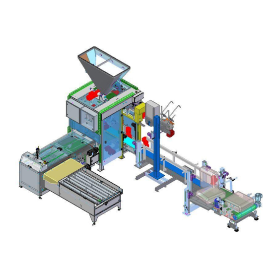
Main component parts For convenience, the OML-1140 Bagger may be described in terms of four main sub-units: Bag magazine Bag dispenser unit Bag fill and transfer modules Bag outfeed modules System modules are also referred to by a standard reference number as shown here. The details of each of the system modules (where used) follows in the subsequent sections. -
Page 21: Illustrations
Illustrations In the sections that follow, illustrations are used to indicate the various machine parts and modules. However, it should be noted that these are not shown to scale and that there may be slight variations between the illustrations and the actual machine/modules in use. Therefore, for further information regarding any particular part or module, reference should be made to the engineering drawings attached as an Appendix to this manual. -
Page 22: Module: Bag Magazine
Module: Bag Magazine Main component parts The main parts of the Bag Magazine are shown below: Basic operation This module holds the bags ready for use and positions the bags ready for the Pick-up Assembly to lift individual bags onto the Grid Chain Conveyor. Stacks of bags are placed on the Bag Magazine and are moved by the fingers towards the Bag Dispenser sub-unit under the control of the main air cylinder. -
Page 23: Manual Bag Width Adjustment
The Bag Magazine Dispenser is provided with several vertical fingers which move under software control to the correct position for the size of bag being used by the system. In operation, the Bag Magazine moves the bags to the Bag Dispenser by the use of sliding finger air cylinders described in the sequence below: 1) The Bag Dispenser requires bags 2) The fingers lower... -
Page 24: Lifting Table
Lifting table Once the empty bags are delivered to the correct position in the Bag Dispenser, they sit on a Lifting Table which changes height as the number of bags in the stack reduces. This ensures that the bags are always optimally placed with respect to the bag pick- up unit vacuum cups ensuring a clean pick-up of single bags at the optimum speed. -
Page 25: Module: Bag Dispenser
Module: Bag Dispenser Main component parts The main parts of the Bag Dispenser are shown below: The Bag Dispenser module comprises other sub-modules as follows: Vacuum Bag Pick-Up Device This module lifts single bags from the Bag Magazine Assembly and places them on the Grid Chain Conveyor in a flat horizontal position with the mouth of the bag facing towards the Bag Alignment Device and Belt Conveyor Assembly. -
Page 26: Grid Chain Conveyor
Grid Chain Conveyor The Grid Chain Conveyor continuously rotates (if bags are being loaded) and transports the individual horizontal bags from the Pick-up Device over the Belt Conveyor Assembly to the Bag Openers. The adjustable guide plates of the Belt Conveyor position the individual bags according to the correct operational alignment required by the bag opener (see below). -
Page 27: Bag Stopper Assembly
Bag Stopper Assembly The centered bags pass under the Bag Stopper Assembly which ensures the bags are pressed into the correct position for the bags to be opened by the Top Bag Opener and the Bottom Bag Opener. The Bag Pressing Device operates by an air cylinder (not shown here) under software control. -
Page 28: Module: Bag Transfer, Bag Transport And Fill, And Outfeed Assemblies
Module: Bag transfer, bag transport and fill, and outfeed assemblies Basic layout: Bag transfer assembly ___________________________________________________________________________________ Version #1 –October 2016... -
Page 29: Bag Opener Sub-Assembly
The Bag Transfer Assembly takes the bags from the Bag Dispenser Unit and moves the bags to the Spout Assembly. The unit is divided into three main parts: Bag opener sub-assembly, lifting motor sub-assembly and transfer arm sub- assembly: Bag opener sub-assembly The Bag Opener fingers are inserted into the bag to keep the bag mouth open as it is transferred to the spout for filling. -
Page 30: Bag Transfer Assembly Operation
Transfer arm sub-assembly From above, the raising and lowering of the hexagonal bars causes the entire transfer arm sub-assembly to rotate around the main shaft sub-assembly (shown in grey here) which will move the opened bag to the spout for filling. The bag is held on the bag spacer fingers by bag side clamps (shown in blue here) and the clamp unit itself is also able to move as a unit under the... -
Page 31: Bag Transport And Spout Assemblies
Bag transport and spout assemblies Spout assembly The spout assembly consists of the following sub-assemblies: The spout is made up of: Fixed chute Purge button (air release valve) Bag clamp assemblies (one unit shown) Spout flap air cylinder (one unit shown) ... -
Page 32: Fixed Chute
Fixed chute The Fixed Chute is used to connect the top of the Spout Assembly to the infeed system. In the current configuration, the top of the Fixed Chute is connected directly to the bottom of the Transition Hopper. Bag clamp assembly Once the empty bags have been delivered to the Spout Assembly by the Transfer Arm Sub- assembly, and the bag has been correctly... -
Page 33: Spout Flaps
Spout flaps The Spout Flaps are opened by two air cylinders (one on each side of the Spout) in order to allow a measured product quantity to discharge into the bag attached to the Spout. The Spout Flaps are attached to adjustable brackets in order that the Spout Flap opening can be accurately set. -
Page 34: Bag Transport Unit
Bag transport unit Motor control sub-assembly The motor control sub-assembly controls the movement (transport) of the filled bag from the Spout Assembly to the Upper Exit Unit and Internal Conveyors. As the motor operates, the gearbox drives a cam assembly which causes the driver arms (shown in pink here) to move causing the complete Transport Arm Sub-assembly to move towards or away from the Upper Exit Unit... -
Page 35: Module: Upper Exit Unit And Conveyor Assemblies
Module: Upper exit unit and conveyor assemblies Lower transport unit The Transport Arm transports the filled bag from the mouth of the Spout to the Lower Transport Unit. Once the filled bag is resting on the conveyor, the posser unit will operate and settle the contents of the filled bag. -
Page 36: Upper Exit Unit Assembly
Upper exit unit assembly The Upper Exit Unit consists of two parts: Upper Exit infeed Unit; Upper Exit Outfeed unit. The Upper Exit Infeed unit accepts the mouth of the filled bag which will be gripped by the swinging belt drive. -
Page 37: Internal Conveyors Assembly
Internal Conveyors assembly As the filled bag is transported to the first Upper Exit Unit, its weight will be supported by the first Internal Conveyor (M1) and its position will be stabilized by the means of a suitably adjusted Bag Stopper (see “Bag Stopper”... -
Page 38: Conveyor Frame With Raising/Lowering Actuators
Assemblies through to the downstream equipment. The bag sealing system (not shown in the drawings) is installed close to the OML-1140 main frame and closes and seals filled bags as the bags pass along the External Conveyors. The height of the External Conveyors can be controlled via the HMI unit –... -
Page 39: Module: Transition Hopper
Module: Transition Hopper The Transition Hopper connects the weigher (not shown in this manual – see separate manual for details) to the OML-1140 Automatic Bagging Machine. It is installed on, and supported by, the main frame of the machine. The Transition... -
Page 40: Bag Specifications And Requirements
BAG SPECIFICATIONS AND REQUIREMENTS Bags that are used with the OML-1140 Bagger must meet certain specifications in order that optimum performance may be obtained, and these specifications are detailed below: Bag dimensions Length: Between 500mm and 1100 mm Width: Between 300mm and 700 mm (depending on spout size) -
Page 41: Bag Storage Requirements
Bag storage requirements Correct handling and storage of bags must be performed in order to prevent bag quality degradation. Bags (laying flat) Bags (side view) Notes: a) Bags must lie flat on their whole length and width. b) The bag surface must be free of folds and/or wrinkles (due to improper storage). Photographs of bags that do not meet the necessary specifications: ___________________________________________________________________________________ Version #1 –October 2016... -
Page 42: Thread Tails
Thread tails For bags with a sewn bottom, thread-tails longer than 20 mm are not acceptable. In case of having “crepe” tape, it should exceed more than 40 mm of the bag width. Transport and storage requirements It is preferable to transport bags on pallets, wooden-boxes or cardboard-boxes rather than in bundles. -
Page 43: Additional Photographs Of Bags That Do Not Meet The Necessary Storage Specifications
Additional photographs of bags that do not meet the necessary storage specifications: Poor storage and transport of the bags to the production line may also lead to bags and bag inner liners becoming wrinkled which will create thickness errors as the bags are being used. This will cause otherwise good bags to be rejected leading to a high level of rejected bags. -
Page 44: Notes Per Bag Type
Notes per bag type PAPER BAGS: Mouth bag lips must be free of any adhesive, which will lead to opening problems. All along the bag mouth edge, paper-ply’s must be correctly secured with regularly spaced dabs of adhesive. PE BAGS: ... -
Page 45: Assembly
ASSEMBLY WARNINGSWARNINGSNINGSO NTENTS ___________________________________________________________________________________ Version #1 –October 2016... -
Page 46: Important Notes
Erection of steel structures as well as basic alignment has to be carried out according to the relevant layout drawing(s) which will be supplied by Premier Tech Chronos. Final alignment and fixing must be supervised by an authorized commissioning engineer. If any additional safety fences are required by local safety authorities, they must be fitted by the customer in accordance with such requirements. -
Page 47: Low Voltage Dc Cable Runs
Low voltage DC cable runs The following recommendations apply: NOTES: 1) All low voltage DC cables should be run in their own steel conduit avoiding other cables as above (see item 3); 2) The exact number of cores should be used in cables there should be no spare cores; 3) More than one low voltage DC cable may be run in the same conduit as another low voltage DC cable but these cables must not be mixed with motor or control cables;... -
Page 48: Control Voltage Ac Cable Runs
Control voltage AC cable runs NOTES: 1) All control AC cables should be run in either steel conduit or as screened multicore cable avoiding other cables as above; 2) The cross-sectional area should be 1.5mm unless otherwise stated. RFI shielding ___________________________________________________________________________________ Version #1 –October 2016... -
Page 49: Earthing
Earthing A clean ground may be made by using any of the following: 1) Ground Rod Most installations can be grounded by driving a 10mm x 2.5m ground rod in the ground within 30 metres of the controller. 2) Grounding to metal water pipes Can be used if resistance to ground is less than 6Ω. -
Page 50: Initial Commissioning
INITIAL COMMISSIONING WARNINGSWARNINGSNINGSO NTENTS ___________________________________________________________________________________ Version #1 –October 2016... -
Page 51: Initial Commissioning
Initial commissioning The OML 1140 Bagging System as provided has already been fully built and tested prior to shipment and will generally only require reassembly and acceptance testing. However, it is recommended that the following items be checked: General The equipment should be clean and free from damage. Any packing material should be removed. If in doubt, refer to the installation engineer. -
Page 52: Manual Adjustments
MANUAL ADJUSTMENTS WARNINGSWARNINGSNINGSO NTENTS ___________________________________________________________________________________ Version #1 –October 2016... -
Page 53: Important Notes
Chronos engineers during pre-installation test runs but may require optimization on site for specific requirements. Equipment should therefore not be adjusted unless authorized by Premier Tech Chronos. WARNING! All final adjustments will be carried out by the commissioning engineer and data regarding these adjustments will be saved as appropriate for reference purposes. -
Page 54: Bag Dispenser
External Conveyor The External Conveyors are used to transport the filled bags from the OML-1140 Automatic Bagger to the Bag Kicker and usually has a sewing machine system attached (not shown in the illustration here). -
Page 55: Bag Turner
1140 Automatic Bagging System will be optimised during commissioning taking into account the speed of the motors which are controlled by separate frequency inverters. If parameter adjustment is required, Premier Tech Chronos should be contacted for assistance. How to adjust the bag thickness limit value Refer to the HMI manual for details on how to adjust the OML1140 for the correct detection of the bags to be used. -
Page 56: Exit Unit Speed
Adjustments in the transport speed can be carried out via the appropriate frequency inverter. Normally this is a fixed parameter adjusted by the commissioning engineer. If parameter adjustment is required, Premier Tech Chronos should be contacted for assistance. Bag Dispenser Speed The basic adjustment of the bag dispenser speed will be carried out during the pre-delivery tests prior to machine installation. -
Page 57: Spout
For function testing – follow the corresponding menu on the operating panel. All functions of the machine can be operated manually by pressing the respective buttons of the desired functions. – refer to the OML-1140 HMI operating manual. ___________________________________________________________________________________ Version #1 –October 2016... -
Page 58: Automatic Operation
AUTOMATIC OPERATION Operation of the OML 1140 Automatic Bagging System Turn the selector switch to AUTO. Press the RESET button. Press the START button. In the event that a FAULT indication appears on the operator panel, this must be cleared and reset before starting the system. -
Page 59: Maintenance
MAINTENANCE WARNINGSWARNINGSNINGSO NTENTS ___________________________________________________________________________________ Version #1 –October 2016... -
Page 60: Warnings
Warnings WARNING! Only qualified personnel with a thorough knowledge of the equipment and its Operating and Maintenance Manual are authorized to perform maintenance procedures. WARNING! The internal parts of this machine can cause serious injury if the machine is operated while adjustments and/or maintenance are being carried out. -
Page 61: General Preventative Maintenance Schedule
Ensure that only approved replacement parts are use when required to avoid possible problems with machine operation and/or machine safety. Premier Tech Chronos Ltd is only responsible for any guarantee if original Premier Tech Chronos Ltd spare parts are used. -
Page 62: Pneumatic Components Lubrication
Pneumatic components lubrication All pneumatic components are pre-lubricated for life. However, if the air is too dry or moist and/or contains dust particles, lubrication is needed to prevent deterioration. Note: Once the lubrication is started, it must not be stopped because it removes the factory pre-lubrication of the pneumatic components. -
Page 63: Feed Conveyor Rod Check/Replacement
Feed Conveyor Rod Check/Replacement The chain grid conveyor rods should be checked on a regular basis and can be visually inspected opening the bag dispenser rear door and checking each of the individual rods. If a rod requires replacement follow this procedure: ... -
Page 64: Grid Chains Tensioning
Grid Chains Tensioning The grid chains should be checked at regular intervals for correct tension. This can be done by checking the movement of the chain between two vertical sprockets which should be between 20mm and 25mm at the point of maximum slack: If the maximum slack is not between these limits, the tension can be adjusted as follows: ... -
Page 65: Access To Motor Gearbox
Access to the motor gearbox Access to the interior of small gearboxes is obtained by removing the assembly screws. The old lubricant can then be easily removed by splashing hot water into or by washing the interior of the gearbox with kerosene or some other non-corrosive detergent. Trichloroethylene must not be used. After cleaning, any excess lubricant or detergent residue must be thoroughly removed. -
Page 66: Motor Maintenance Procedure
Motor maintenance procedure If the motor requires maintenance, use the following procedure: Disconnect the motor and uncouple the motor from the gearbox. Remove the cover and the fan which is keyed, clamped, pinned or knurl located to the shaft extension. Remove the drive pinion, bearing cover and screws and end shield bolts/studs. -
Page 67: Lubricant Quantities
Lubricant quantities The optimum amount of lubricant required for each unit must be determined in accordance with the manufacturer’s recommendations. Lubricating roller bearings Roller bearings fitted in the various gear units are charged at the works with roller-bearing grease but during operation they are lubricated by the gearbox lubricant. -
Page 68: Pneumatic Cylinders
Pneumatic cylinders In principle, all pneumatic cylinders are maintenance-free although a visual check, especially of the rod gasket for leakage, should be carried out regularly in addition to listening for leaks (leakage whistles). If necessary the gasket or the whole air cylinder can be replaced. All rod ends must be greased with a Li-saponified grease whenever necessary. -
Page 69: Location Of The Vacuum Generators And Filters
Location of the vacuum filters BAG TOP OPENER VACUUM FILTER BAG BOTTOM OPENER Bag Dispenser bag pick-up unit Bag Dispenser top and bottom bag openers ___________________________________________________________________________________ Version #1 –October 2016... -
Page 70: Maintenance Schedule
Maintenance schedule WARNING! The internal parts of this machine can cause serious injury if the machine is operated while adjustments and/or maintenance are being carried out. Power from all sources (electrical, hydraulic, pneumatic, etc.) must be switched OFF and LOCKED OUT and TAGGED following local safety procedures before performing equipment maintenance, cleaning, adjustment or the clearing of jammed bags or other blockages. -
Page 71: General Maintenance - Pneumatic Cylinders
General maintenance - Pneumatic cylinders Action Daily Weekly Monthly 3-monthly Yearly Remarks Check cushion adjustment Adjust as necessary Check gaiters and seals for damage Replace worn parts as necessary and signs of failure Examine bearings and bushes for signs ... -
Page 72: General Maintenance - Bag Clamps And Sucker Heads
General maintenance - Bag clamps and sucker heads Action Daily Weekly Monthly 3-monthly Yearly Remarks Check clamps for smooth operation Replace if necessary and damage Check flexible tubes for damage Replace if necessary and/or leaks Check suction cups for damage ... -
Page 73: Bag Lifting Table
Bag lifting table Action Daily Weekly Monthly 3-monthly Yearly Remarks Check photo sensors [send and receive] for Clean adjust or replace as required correct alignment and operation Check the lifting sprocket is free of material Clean and lubricate as necessary Check the lifting chain is clean and free of ... -
Page 74: Bag Opener Top Vacuum Device
Bag opener top vacuum device Action Daily Weekly Monthly 3-monthly Yearly Remarks Check vacuum generator filter unit and Replace if necessary clean Check sensors for correct alignment and Adjust or replace as required operation ENSURE POWER IS Check sensors electrical connections DISCONNECTED ... -
Page 75: Vacuum Pick Up Device Assembly
Vacuum pick up device assembly Action Daily Weekly Monthly 3-monthly Yearly Remarks Check vacuum generator filter unit and Replace if necessary clean Check cover assembly safety switch Replace or adjust as necessary for correct operation Check sensors for correct alignment ... -
Page 76: Chain Driver Assembly
Chain driver assembly Action Daily Weekly Monthly 3-monthly Yearly Remarks Check ball bearings are running evenly Replace if necessary Lubricate ball bearings Check sprockets for wear and damage Replace if necessary Check flange bearings and are running ... -
Page 77: Pneumatic Service Unit
Pneumatic service unit Action Daily Weekly Monthly 3-monthly Yearly Remarks Check silencers for damage and correct Replace if necessary operation Check flexible tubes for damage Replace if necessary and/or leaks Check couplings and fittings for damage Replace if necessary and/or leaks Check all pneumatic parts for correct ... -
Page 78: Transfer Module [27]
TRANSFER MODULE Transfer module Action Daily Weekly Monthly 3-monthly Yearly Remarks Clean clamps with compressed air Check cam assembly for correct Replace if necessary operation and damage Check clamp rubber for damage Replace if necessary Check clamps for smooth operation ... -
Page 79: Driving Unit
Driving unit Action Daily Weekly Monthly 3-monthly Yearly Remarks Check bearings are running evenly Replace if necessary Lubricate bearings ENSURE POWER IS Check electrical connections of motor and tighten if necessary DISCONNECTED Inspect gearbox for damage and signs ... -
Page 80: Hopper [32]
HOPPER Hopper Action Daily Weekly Monthly 3-monthly Yearly Remarks Check threaded rods for smooth Lubricate if necessary operation Check threaded rods for damage Replace if necessary Check adjust flow plate for damage Replace if necessary and wear Hammer unit Action Daily... -
Page 81: Spout Sub-Assembly
Spout sub-assembly Action Daily Weekly Monthly 3-monthly Yearly Remarks Check silencers for damage and correct Replace if necessary operation Check flexible tubes for damage Replace if necessary and/or leaks Check mechanical valve (purge valve) for Replace if necessary damage and correct operation ... -
Page 82: Spout Up/Down Device [48]
SPOUT UP/DOWN DEVICE Spout up/down device Action Daily Weekly Monthly 3-monthly Yearly Remarks Check sensors for correct alignment Adjust or replace as required and operation ENSURE POWER IS Check electrical connections of sensor DISCONNECTED ENSURE POWER IS Check electrical connections of motor ... -
Page 83: Wrist Assembly
Wrist assembly Action Daily Weekly Monthly 3-monthly Yearly Remarks Check ball bearings are running evenly Replace if necessary Lubricate ball bearings Check nuts are tight Tighten if necessary Pneumatic gripper assembly Action Daily Weekly Monthly 3-monthly Yearly Remarks Check ball polyurethane blocks on ... -
Page 84: Air Jet Assembly
Air jet assembly Action Daily Weekly Monthly 3-monthly Yearly Remarks Check the air jets are clean and that air Clean if blocked passes unobstructed through the jets Rod assembly Action Daily Weekly Monthly 3-monthly Yearly Remarks Check the hanger units operate evenly Replace if necessary ... -
Page 85: Upper Exit Unit [62]
UPPER EXIT UNIT Upper exit unit Action Daily Weekly Monthly 3-monthly Yearly Remarks Check proximity sensor for correct Adjust or replace as required alignment and operation Check proximity sensor electrical ENSURE POWER IS connections DISCONNECTED Check bearing assemblies are running ... -
Page 86: Transmission Assembly
Transmission assembly Action Daily Weekly Monthly 3-monthly Yearly Remarks Check bearing assemblies are running Replace if necessary evenly Lubricate bearing assemblies Check UHMW flat bar for wear Replace if necessary Check timing pulleys are running evenly Replace if necessary ... -
Page 87: Frame
Frame Action Daily Weekly Monthly 3-monthly Yearly Remarks Check actuator for smooth operation Replace if necessary ENSURE POWER IS Check the electrical connections of the actuators and tighten if necessary DISCONNECTED Refer also to manufacturer's As req'd As req'd As req'd As req'd As req'd... -
Page 88: External Conveyors [82]
EXTERNAL CONVEYORS: Belt conveyor Action Daily Weekly Monthly 3-monthly Yearly Remarks Check side guides for wear or damage Replace if necessary Check tail roller is rotating freely Lubricate; replace if necessary Replace damaged part or entire belt if ... -
Page 89: Pneumatic Unit
Pneumatic unit Action Daily Weekly Monthly 3-monthly Yearly Remarks Check silencers for damage and correct Replace if necessary operation Check flexible tubes for damage Replace if necessary and/or leaks Check couplings and fittings for damage Replace if necessary and/or leaks Check all pneumatic parts for leaks and ... -
Page 90: Tension Roller Unit
Tension roller unit Action Daily Weekly Monthly 3-monthly Yearly Remarks Check ball bearings are running evenly Replace if necessary Lubricate ball bearings Drive pulley unit Action Daily Weekly Monthly 3-monthly Yearly Remarks Check mechalocks are tight Tighten if necessary ___________________________________________________________________________________ Version #1 –October 2016... -
Page 91: Other Information
OTHER INFORMATION WARNINGSWARNINGSNINGSONTENT ___________________________________________________________________________________ Version #1 –October 2016... -
Page 92: Explanation Of Lubricant Symbols According To Din 51 502
Explanation of Lubricant Symbols According to DIN 51 502 The different lubricants used are identified by special distinguishing marks (consisting of letters, numbers, or additional letters) and of simple symbols (geometric shapes). The color in all cases is white. Oil grades and lubricating intervals are to be noted from the respective manufacturers’ instructions. Chain drives should be cleaned of abrasions, contamination and resinification, by means of, for example, kerosine or petroleum and be regreased afterwards, preferably using a special chain lubrication spray. -
Page 93: Greases
Greases Symbol for lubricating greases with a mineral base Identifying letter for greases intended for rolling bearings, sliding bearings and sliding surfaces within a working temperature range from -20 to +140°C Identifying letter for lubricating greases intended for high compressive stress in a working temperature range of -20 to +140°C Corresponds to 265 –... -
Page 94: Lubricant Grades
Special types of grease are available for other operating temperatures, and such cases should be discussed and implemented with the assistance of Premier Tech Chronos only. Where the break-away torque has been reduced to provide a soft starting characteristic, an additional... - Page 95 140) or AGMA 8 EP should be used. The type of lubricant selected by the manufacturer for the initial filling can be ascertained by referring to the plate on the gear unit or by enquiring from Premier Tech Chronos. ___________________________________________________________________________________...
-
Page 96: Gear Oil Tables
Gear Oil Tables The following mineral oils are permitted: Temperature range Viscosity ARAL ESSO -5° C ... +40° C ISO VG 220 Degol BG 220 BP Energol Deagcar DX Spartan EP (normal) GR-XP 220 SAE 85W-90 Falcon CLP - 15° C ... +25° C ISO VG 100 Degol BG 100 BP Energol... - Page 97 The following mineral-oil-based low-viscosity greases are permitted: Temperature range Viscosity ARAL ESSO -20° C ... +50° C Aralub FDP 00 BP-Energrease Orona GF Fibrax EP 370 (normal) HT-00 EP 1464-00 FG-00-EP Temperature range Viscosity KLÜBER MOBIL SHELL -25° C ... +80° C Natobin 8 1600 Mobilex 44 Shell special gear viscosity H...
-
Page 98: Fault Diagnosis
FAULT DIAGNOSIS WARNINGSWARNINGSNINGSO NTENTS ___________________________________________________________________________________ Version #1 –October 2016... -
Page 99: Fault Diagnosis
Fault diagnosis The OML 1140 Automatic Bagging System is provided with a very sophisticated fault diagnosis system which permanently operates in the background as the system is in operation. In the event of a problem, the details will be shown on the operator screen and these details will allow the operator to quickly solve most problems. -
Page 100: Engineering Drawings
ENGINEERING DRAWINGS WARNINGSWARNINGSNINGSO NTENTS ___________________________________________________________________________________ Version #1 –October 2016... -
Page 101: Engineering Drawings Attached As
Engineering drawings as attached in Appendix A All the engineering drawings that are necessary for information are attached in Appendix A. If further information is required, requests should be made to Premier tech Chronos using the contact details at the end of this manual. -
Page 102: Spare Parts
SPARE PARTS LISTS WARNINGSWARNINGSNINGSO NTENTS ___________________________________________________________________________________ Version #1 –October 2016... -
Page 103: Spare Parts
In this case, a reduced number of spares can be held. Premier Tech Chronos is available to assist with the ordering of a set of spare parts that will suffice for most installations. -
Page 104: Bag Dispenser Spares
Bag Dispenser spares Drawing Drawing Item ref Part number Item name Recommended reference title on drawing on drawing on drawing spares holding BOM17B0000A-SM16-00032 Rev 2 Bag dispenser 372590 Proximity sensor 372232 Sensor socket/cable 370889 Flow control valve 370709 Proximity switch 370667 Angle connection 3193321... -
Page 105: Transfer Module Spares
Transfer module spares Drawing Drawing Item ref Part number Item name Recommended reference title on drawing on drawing on drawing spares holding BOM27B0400A-2 Rev 2 Spreader assembly 372659 Air cylinder 372590 Proximity switch 372319 Mounting kit 372232 Connecting cable 372224 Flow control valve BOM27A0300A-2 Rev 1 Spacers assembly... -
Page 106: Internal Conveyor Spares
Upper exit unit spares Drawing Drawing Item ref Part number Item name Recommended reference title on drawing on drawing on drawing spares holding BOM62A0000M-2 Rev 0 Upper exit unit BOM62A0100A-2_C/S Universal joint BOM62A0100A-2 Universal joint 372625 Timing belt 372590 Proximity sensor 372519 Air cylinder 372232... -
Page 107: Summary Of Parts And Overall Recommendations For Spares Holdings
Summary of spare parts and overall recommendations for spares holdings ___________________________________________________________________________________ Version #1 –October 2016... - Page 108 ___________________________________________________________________________________ Version #1 –October 2016...
- Page 109 ___________________________________________________________________________________ Version #1 –October 2016...
-
Page 110: How To Order Spare Parts
Quantity required: Following these guidelines will save you and our spare parts department check backs and therefore loss of time. Send details to: Premier Tech Chronos Limited 93 Moo, 9 Bangna-Trad, Km 19 Road, Tambol Bang Chalong, Amphor Bangplee Samutprakan 10540... -
Page 111: Glossary
GLOSSARY WARNINGSWARNINGSNINGSO NTENTS ___________________________________________________________________________________ Version #1 –October 2016... -
Page 112: Bag Magazine Assembly
Bag Magazine Assembly Ref Part Ref Part 1 Bag magazine table 15 Sensor assembly 2 Bag magazine adjustment 16 Lifting table lifting motor 3 Adjustable plate 17 Carriage assembly 4 Bag width adjustment sub-assembly 18 Solenoid valve 5 Stainless steel round bar 19 Silencer 6 Adjustment handle 20 Solenoid valve cable/socket... -
Page 113: Bag Dispenser Assembly
Bag Dispenser Assembly General layout Vacuum bag pick-up device Vacuum bag pick-up device Part Flow control valve Air cylinder Proximity sensor Case Emergency stop Polycarbonate door ___________________________________________________________________________________ Version #1 –October 2016... -
Page 114: Chain Conveyor And Drive
Part Flow control valve Air cylinder Proximity sensor Case Emergency stop Polycarbonate door Guide unit Door safety switch Vacuum generator Vacuum filter Vacuum suction cup Stopper Non-return valve Chain conveyor and drive Part Gearmotor Chain sprocket Flange bearing Drive shaft Fibreglass rod assy Conveyor belt Conveyor chain... -
Page 115: Bag Alignment Device
Bag alignment device Part Main shaft Counterweight Locking mechanism Alignment wheel Rubber 'O' ring Belt conveyor assembly Part Manual width adjustment handle Screw bar assembly Bearing Bag alignment plate Conveyor gearmotor Nylon square bar Conveyor belt Conveyor driven shaft Conveyor driving shaft Housed bearing Bag stopper assembly Part... -
Page 116: Top Opener
Top opener Part Inductive sensor with socket/cable One-way flow control Thickness gauge inductive sensor Air cylinder/guide drive Vacuum cup assembly Vacuum generator (top bag opener) Vacuum filter (top bag opener) Bag dispenser main frame Vacuum filter (top bag opener) Notes: The vacuum generator [6] and filter [7] for the top bag opener is located on the inside of the main bag dispenser frame [8]. -
Page 117: Bottom Opener
Bottom opener Part Vacuum filter assembly Vacuum cup assembly Air cylinder Bag Transfer Assembly Location The Bag Transfer assemblies are located in the OML-1140 Bagging system as shown here: ___________________________________________________________________________________ Version #1 –October 2016... -
Page 118: Sub-Assemblies
Sub-assemblies There are three main sub-assemblies in the main Bag Transfer assembly: Lifting motor sub-assembly; Transfer Arm sub-assembly and Bag Opener sub-assembly: Lifting motor sub-assembly Part Gear motor Bumper rubber Drive shaft Drive shaft bearing Cam assembly Bearing Link bar ___________________________________________________________________________________ Version #1 –October 2016... -
Page 119: Transfer Arm Assembly
Transfer Arm sub-assembly NOTE: THE TWO ARM POSITION SENSORS [5] ARE LOCATED ON THE MAIN FRAME. THEY ARE SHOWN HERE RELATIVE TO THE SENSOR DETECTION PLATE [6] OR THE TRANSFER ARM FOR REFERENCE Part Part Spreader assembly Bearings Link Proximity sensor Main shaft assembly Air cylinder (lower clamp) Rod assembly... -
Page 120: Bag Transport And Spout Assemblies
Bag Transport and Spout assemblies Location Spout: Sub-assemblies ___________________________________________________________________________________ Version #1 –October 2016... -
Page 121: Spout Assembly
Spout assembly Part Fixed chute Timing lever Spout opening cylinder Swivel arm/dust clamp assembly Ball bearing Rod eye Bag clamp assembly Outside spout flap Inside spout flap Mechanical release valve Bag clamp assembly Part Bag clamp air cylinder Rubber clamp Spout clamp Spout clamp pivot Rod eye... -
Page 122: Dust Clamp And Swivel Arm Assembly
Dust clamp and swivel arm assembly Part Top clamp air cylinder bearing Top clamp air cylinder Pivot support Top clamp arm Dust clamp air cylinder Clamp arm Dust clamp rubber Clamp mounting Swivel bearing Spout Up/Down Assembly Part Gear motor Parallel arm Top plate assembly Frame... -
Page 123: Bag Transport Assembly
Bag Transport Assembly Part Part Gearmotor Flow control unit Bumper rubber Wrist assembly Driving shaft Spreader assembly Link bar Ball bearing Arm assembly Spreader unit air cylinder Bearing Pneumatic gripper assembly Nylon shaft Gripper unit air cylinder Parallel arm assembly Gripper flow control unit Air jet assembly Gripper finger... -
Page 124: Outfeed Unit Assemblies
Outfeed unit assemblies Location Upper Exit Unit Part Sensor Air cylinder Bearing Bearing assembly Shaft (open/close belt units) Telescoping universal joint (with bellows) Bellows Main drive pulley Drive belt Gearmotor Belt pulley Bag guide Telescoping universal joint (standard) Note: Motor shown without cover ___________________________________________________________________________________ Version #1 –October 2016... -
Page 125: Lower Transport Unit With Posser
Lower Transport Unit with Posser Part Gearmotor (conveyor) Belt Driving roller Conveyor bearing Sensor assembly Driven roller Swivel frame Air cylinder Proximity switch Flow control valve Cam assembly Gearmotor (posser) Internal Conveyor Unit – Overall ___________________________________________________________________________________ Version #1 –October 2016... -
Page 126: Internal Conveyor Unit - Conveyors
Internal Conveyor Unit – Conveyors Part Gearmotor (conveyor 1) Belt (conveyor 1) Driving roller (conveyor 1) Driving roller bearing (conveyor 1) Sensor assembly Gearmotor (conveyor 2) Reflector assembly Belt (conveyor 2) Driving roller (conveyor 2) Driving roller bearing (conveyor 2) Internal Conveyor Unit –... -
Page 127: External Conveyor On Frame
External conveyor (on frame) Part Adjustable bag guide Bag guide adjusters Driven roller Actuator Frame Junction box Driving sprocket roller Plastic link belt Main roller bearing Gearmotor Bag turner Part Bag support Driven roller Bag guide Turning post Turning post adjustment Sensor assembly (behind guide) Rail (guide) adjustment Rail (guide) assembly... -
Page 128: Transition Hopper
Transition hopper Part Hopper frame Hammer unit Silencer Air cylinder Exhaust controller Solenoid valve and coil Main frame Part Frame Mainframe cover Main door assembly (with safety switch) Pneumatic cabinet Electrical cabinet ___________________________________________________________________________________ Version #1 –October 2016... -
Page 129: Contact Us
CONTACT US WARNINGSWARNINGSNINGSO NTENTS ___________________________________________________________________________________ Version #1 –October 2016... -
Page 130: By Mail Or Telephone
By mail or telephone Premier Tech Chronos Limited 93 Moo 9, Bangna-Trad Km. 19 Road, Tambol Bang Chalong, Amphor Bangplee, Samutprakarn 10540, Thailand Tel: +66 (0) 2740 5001 Fax : +66 (0) 2312 6836 Service Hot-line - Thailand Please contact us via:...
Need help?
Do you have a question about the OML-1140 and is the answer not in the manual?
Questions and answers
I'm operating a premier tech OML 1140. I'm stuck in off mode, can't start bagger.
To troubleshoot the Premier Tech Chronos OML-1140 bagger stuck in off mode, follow these steps:
1. Check Starting Preconditions: Ensure the following:
- The closing system is switched on.
- The main switch is turned to "ON."
- The weigher(s) and conveyor are switched on and properly interlocked with the bagging system.
- The minimum air pressure is set between 5.0 – 6.0 bar.
- The bag magazine is filled.
2. Perform a Function Test: Manually test the functions using the corresponding menu on the operating panel (refer to the HMI operating manual).
3. Switch to Automatic Mode:
- Turn the selector switch to "AUTO."
- Press the RESET button.
- Press the START button.
4. Check for Fault Indications: If a FAULT indication appears on the operator panel, address the issue displayed before proceeding.
Following these steps should help identify and resolve the issue.
This answer is automatically generated