
Related Manuals for Elektromaten TS 981


Summary of Contents for Elektromaten TS 981
- Page 1 Electrical operating instructions Door control panel TS 981 Software 2.6 (Design and functions subject to change) 51171314 - l 02.2013...
-
Page 2: Table Of Contents
SAFETY DIRECTIONS ....................4 INSTALLATION ADVICE ....................6 INSTALLATION OVERVIEW ..................7 ENCLOSURE INSTALLATION ..................8 ® CONNECTING THE CONTROL AND THE ELEKTROMATEN ............MAINS SUPPLY ......................9 PHASE ROTATION ....................... 10 MOTOR CONNECTION (internal wiring) ..............10 RAPID ADJUSTMENT OF THE LIMITS ............... 11 HARDWARE OVERVIEW ..................... - Page 3 Page Pass door / slack rope switch input X2 ................30 Emergency stop X3 ....................... 30 FUNCTION DESCRIPTION ..................31 Internal push button / Three push button / Key switch X5 / X15 ........31 Automatic closing ......................31 Automatic closing interruption ..................31 Through / Reflective photo cell X6 / X16 or Light curtain X6 ..........
-
Page 4: Safety Directions
Liability ceases to apply if other parts are used. The operational safety of an TS 981 is only guaranteed if it is used in accordance with the regulations. The limiting values stated in the technical data should not be exceeded under any circumstances (see corresponding sections of the operating instructions). - Page 5 DANGER This indicates danger to the life and health of the user if the appropriate precautions are not taken. CAUTION This warns that the ELEKTROMATEN ® or other materials may be damaged if the appropriate precautions are not taken. General warnings and safety precautions The following warnings are to be understood as a general guideline for working with the ®...
-
Page 6: Installation Advice
INSTALLATION ADVICE After the ELEKTROMATEN ® is fitted we recommend the following procedure to rapidly reach a fully functioning door. • Installation Enclosure installation page 8 • Installation Wiring the Drive to the Control page 8 • Check Mains supply page 9 •... -
Page 7: Installation Overview
INSTALLATION OVERVIEW Important! Using the connection cable out side the building is not permitted. ® Connection cable ELEKTROMAT Motor and DES ( electronic limit) Spiral cable for Safety edge system Mains supply Photo-beam Pull switch Three push button Key switch (latching) interrupt automatic closing Emergency stop Key switch (latching) inter-... -
Page 8: Enclosure Installation
Motor plug to control unit - Wire-No. Excution: Phase W Phase V Phase U Neutral (N) (not used) Earth Limit plug-in to control panel TS 981 (DES) - Wire-No. Excution: Safety chain 24V DC RS485 B RS485 A Safety chain 8V DC... -
Page 9: Mains Supply
The supply disconnect device (Main switch or CEE plug) must be installed between 0,6m and 1,7m above floor level. The Control panel TS 981 has a universal electric supply and works with the following supplies. (See diagram Fig.1-5) Mains supply terminal Fig.: 1... -
Page 10: Phase Rotation
UPWARDS if the OPEN push button is operated. If the door does not OPEN change first phase rotation. ® For all three phase ELEKTROMATEN even DU: Change wiring at terminal X1: 1.1 – 1.2. ®... -
Page 11: Rapid Adjustment Of The Limits
RAPID ADJUSTMENT OF THE LIMITS When the phase rotation has been checked the Rapid limit adjustment can be made. The final setting can be made with the fine adjustment (Control Programming page 19). Safety limits and pre-limits are automatically adjusted. 1. -
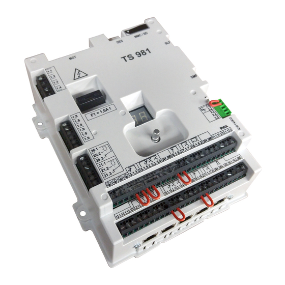
Page 12: Hardware Overview
HARDWARE OVERVIEW MMC/SD MMC / SD TS 981 F1 = 1,6A t 20.1 20.2 20.3 21.1 21.2 21.3 3.1 3.2 5.1 5.2 5.3 5.4 24V GND 6.1 6.2 7.1 7.2 8.1 8.2 24V GND 11.1 11.2 12.1 12.2 15.1 15.2 15.3 15.4 24V GND 16.1 16.2 17.1 17.2 18.1... - Page 13 HARDWARE OVERVIEW Description Print: Mains supply external supply 230V 1.9 = L1 L1 fused with F1 = 1,6A 1.8 = N (only with 3 x 400V, N, PE und 1 x 230V, N, PE symmetric winding) Safety edge system and pass-door plug Emergency push button Key switch for intermediate stop Key switch ON / OFF for automatic closing...
-
Page 14: Wiring Diagram
WIRING DIAGRAM L1 fused N L1 via F1 = 1,6At Bridge Normallyclosed contact 1K2 pass or / slack wire switch contact spiral or crash end-of-line cable detector plug-in bridge resistor 1K2 Terminal box Bridge Normallyopen contact 8K2 pass or / slack wire switch contact spiral... - Page 15 WIRING DIAGRAM outside inside Transmitter- Receiver Reflective photo-beam Transmitter- Receiver photo-beam inside or outside light curtain inside or outside inside for closing direction Key switch ON / OFF Key switch ON / OFF Ceiling pull switch / Intermediate stop automatic closing Radio control inside or outside external...
- Page 16 WIRING DIAGRAM Input for external entrapment Input for external entrapment safety device 1K2 safety device 1K2 single double Input for safety edge 8K2 Input for safety edge 8K2 against entrapment against entrapment single double Transmitter - Receiver Transmitter - Receiver gr 1 gr 1 Raytector photo-beam or...
- Page 17 WIRING DIAGRAM Transmitter - Receiver Transmitter - Receiver photo-beam single, against entrapment comply EN 12978 Receiver - Transmitter photo-beam double, against entrapment comply EN 12978 Potential free Potential free relay contact relay contact Page 17...
-
Page 18: Control Programming
CONTROL PROGRAMMING Enter programming Mode Press selector switch for 3 sec. until display = 00 Chose program and confirm Turn selector Press selector Adjustment Functionen Door position Turn selector Press foil buttons Memorise Functionen Door position Press selector Press stop-button further adjustments Exit programming Turn selector until display = 00... -
Page 19: Operating Mode
CONTROL PROGRAMMING Choose program and Adjustment Memorise confirm Operating mode Door function Dead man OPEN Press Dead man CLOSE selector Self-hold OPEN Dead man CLOSE Self-hold OPEN Self-hold CLOSE Self-hold OPEN, CLOSE (X5/X15) release for external pushbutton function only dead man close Door position Final limit open... -
Page 20: Functions
CONTROL PROGRAMMING Choose program and Adjustment Memorise confirm Functions Safety edge function in Press Safety edge is activated Pre - limit area selector Safety edge is deactivated Safety edge is activated + automatic ground adjustment Active safety edge + re-open Overrun correction Press selector... -
Page 21: Safety Functions
CONTROL PROGRAMMING Adjustment Memorise Choose program and confirm Functions Function Relay 1 Press only available with selector menu 1.7 Switch contact impulse: 1sec. Function Relay 2 only available with Switch contact continuous menu 1.8 Switch contact impulse: 1sec. by open - commands Extended switch contact similar NES cam Light curtain testing at final Open position before closing... - Page 22 CONTROL PROGRAMMING Memorise Chose program and Adjustment confirm Safety functions Photo beam interrupt Press function selector Function: Door safety Press Slake rope / Pass door switch selector Crash detector via NC Contact Crash detector via NO Contact RWA smoke draining – po- Move to RWA position, up to a mini- Press stop...
-
Page 23: Settings Only For Elektromaten ® With Direct / Frequency Inverter Du/Fi
CONTROL PROGRAMMING Choose program and Adjustment Memorise confirm ® Settings only for ELEKTROMATEN with direct / frequency converter DU/FI OPENING speed Press Output speed rpm selector CLOSING speed Output speed rpm Press selector HIGHER CLOSING Increased output speed down to door... -
Page 24: Extended Door Functions
CONTROL PROGRAMMING Choose program and Adjustment Memorise confirm Extended door functions Traffic light management Press selection selector One-way traffic Two-way traffic - priority OFF Two-way traffic - priority inside Two-way traffic - priority outside Extended green light Adjustment 0 - 90 seconds Press period selector... -
Page 25: Maintenance Cycle Counter
CONTROL PROGRAMMING Chose program and Adjustment Memorise confirm Maintenance cycle counter Counter adjustment 01-99 correspond from 1.000 up to 99.000 Press Count down cycles selector Reaction when Display appears „CS“ and adjusted num- Press reaching 0 ber of cycles selector Changing to DEADMAN display appears „CS“... -
Page 26: Reset
RESET Chose program and Adjustment Memorise confirm RESET except cycle- Reset Press stop and Program change button counter 3 sec. SOFTWARE Chose program and Adjustment Loading confirm Software loading Press stop Select required software version from S-D card button 3 sec. Chose program and confirm Software saving... -
Page 27: Safety Devices
SAFETY DEVICES Door safety switch This switch could be fitted on to the surface of the door and will be connected with the spiral cable into the control panel. This door safety switch can used and programmed in two functions. Menu 3.4 a change of function can be realised. -
Page 28: Typ 2: Resistance Evaluation 8K2 With Normally Open Safety Edge Contact
The three core plug must be connected to the safety edge terminal. The control panel TS 981 recognizes on first installation the safety edge system being used. If passdoor / slack wire switch contact exists, remove bridge at terminal ST and ST+ in the terminal box. -
Page 29: Function Of The Safety Edge System
SAFETY DEVICES Function of the safety edge system With Menu 2.1 the function of the safety edge system can be chosen. Function Reaction following the activation Active safety edge stop De-activated safety edge no reaction, door moves until final limit close only for folding doors Active safety edge+ stops and automatically re-adjusts the final limit with the... -
Page 30: Pass Door / Slack Rope Switch Input X2
SAFETY DEVICES Pass door / slack rope switch input The pass door switch Entrysense features a protective function complying with safety category 2 under EN 954-1. The electrical contact is monitored by the control panel that outputs fault F1.7 when it malfunctions. The electronic pass door switch Entrysense: function and test The pass door switch Entrysense is fitted with two reed contacts that are switched by a perma- nent magnet. -
Page 31: Function Description
FUNCTION DESCRIPTION X5 / X15 Internal push button / Three push button / Key switch Internal and external push button Internal and external push button working seperately from each other. Pushing at the same time, the internal push button has priority. Important note! Dead man mode UP and DOWN with internal push button. -
Page 32: Through / Reflective Photo Cell X6 / X16 Or Light Curtain X6
FUNCTION DESCRIPTION X6 / X16 Through / Reflective photo cell or Light curtain Photo cell X6 / X16 A photo cell is used for presence detection. It is only active in door operating mode „3“ and „4“, in the OPEN limit position or during the closing operation. If the photo cell is interrupted, fault indication „F2.1“... - Page 33 FUNCTION DESCRIPTION Advanced photo cell interrupt function Menu 2.4: Function Photo cell interrupt functions „0“ No function „1“ automatic closing The door closes 3 seconds after the photo cell is re-made „2“ vehicle recognition As above „1“ but the photo cell must be obstructed for more than 1.5 seconds.No function if the photo cell is obstructed for less than 1.5 seconds Photo cell ignore function: Menu 3.2:...
-
Page 34: Ceiling Pull Switch / Radio Control X7 / X17
FUNCTION DESCRIPTION X7 / X17 Ceiling pull switch / Radio control It is possible to connect a ceiling pull switch or a radio receiver. The radio receiver's switching contact must be potential free. Menu 2.6: Several types of commands can be adjusted. With each command (impulse) the shutter operates in the following sequences. -
Page 35: Key Switch (Latching) Interrupt Automatic Closing X11
, RWA-function activated. Light indicator for traffic control TS 981 control have a complete one-way and two-way traffic light management integrated. Two pairs of red/green light indicators may be connected on terminal X13. Supply voltage for these light indicators is selectable and could be provided from external or directly from internal terminals X1 1.8 / 1.9. - Page 36 FUNCTION DESCRIPTION Menu 6.1 Traffic light management The integrated traffic light management of TS 981 supplies two traffic modes One-Way Two-Way One-Way mode: This could be selected if the shutter width delivers enough space for two cars driving through the door. The lights indicating only when the shutter is fully OPEN.
-
Page 37: Safety Against Entrampment X18
This function works only when the shutter moves upwards. If safety devices would be activated the shutter stops and reverses to downwards direction for 2 seconds. With Menu 3.7 can be selected whether one ore two entrees shall be activated. The TS 981 works with four several evaluating principles. Principle To be used... -
Page 38: Door Overload Monitor
FUNCTION DESCRIPTION Door overload monitor The door overload monitor recognises that a person is being lifted by the door (hanging on a handle, etc.) and could be adjusted within Menu 3.1 with a possibility of two steps of sensitivity. Adjustment 0.1 sensitive reaction and adjustment 0.2 insensitive reaction Important! After programming the force monitoring the door must perform a complete opening and closing cycle in automatic mode, during which... -
Page 39: Air Look Slf
AIR look SLF Air-lock management could be realised by means an easy electrical cable connection between two shutters with TS 981. The required module with cable should be connected into SLF plug-in. This module would be delivered complete within a manual. -
Page 40: Software Update
FUNCTION DESCRIPTION Software Update For software updates TS 981 have a MMC/SD card slot available. With this function the software can be updated respectively in external places saved. For that purpose the new program can be taken from a PC with special card reader function for GFA cards, following the card could be guided into the control panel existing slot. -
Page 41: Operating Status Display
OPERATING STATUS DISPLAY The control TS981 can display up to three different status conditions one after another. Each status is displayed with a letter and a number. The letter and the number are flashing alternately, thereby the control differentiates between a FAULT = F and a command = E. Report Description Measure to solve the problem... - Page 42 OPERATING STATUS DISPLAY Report Description Measure to solve the problem Safety edge 8k2 defect Check safety edge and connecting cable are not broken Check safety edge and connecting cable are not Safety edge 1K2 activated broken Safety edge 1k2 defect Check safety edge and connecting cable do not have a short circuit Safety edge 1k2 pneumatic...
- Page 43 OPERATING STATUS DISPLAY Report Description Measure to solve the problem ROM - Fault Fault acknowledgement: open and close the pass door switch or switch OFF and ON the main switch or disconnect and reconnect the mains plug. Internal fault report Fault acknowledgement: open and close the pass door switch or switch OFF and ON the main switch or disconnect and reconnect the mains plug.
- Page 44 OPERATING STATUS DISPLAY Report Description Measure to solve the problem Closing rpm over speeded at Fault acknowledgement: switch OFF/ON on the mains DU / FI or disconnect and reconnect the mains plug and if the fault reappears replace the frequency inverter. Internal FI communication fault Fault acknowledgement: switch OFF/ON on the mains or disconnect and reconnect the mains plug and if the...
- Page 45 OPERATING STATUS DISPLAY Report Command description open command being given stop command being given close command being given adjusted cycles for maintenance reached Display off = short circuit or overload at the 24V DC supply Report Status opening flashing closing flashing door stopped between set limits door stopped at upper limit...
-
Page 46: Technical Data
190mm x 300mm x 115mm (W x H x D) Mounting vertical ® ELEKTROMATEN Supply Three-phase 3 x 230 / 400V AC ± 5%, 50...60Hz Single-phase 1 x 230V ± 5%, 50...60Hz Power max. at 3 x 400V AC, max. 3kW Control supply via L1,L2 400V AC or 230V AC + - 10%, 50-...60Hz,... -
Page 47: Lifetime / Doorcykles
Therefore we recommend a ® replacement for control boards in use after doors having reached their confirmed lifetime cycles. Coherence between power and amount of cycles for ELEKTROMATEN describes ® diagram bellow. -
Page 48: Declaration Of Incorporation
Wiesenstr. 81, 40549 Duesseldorf (Heerdt), Germany hereby declare that the following products are conform with the above EC Guidelines and are only intended for installation in door equipment. Door control panel TS 981 Standards applied DIN EN 12453 Doors - safety in use of power operated doors... -
Page 49: Function Overview
FUNCTION OVERVIEW • Control panel for ELEKTROMATEN ® up to. 3 kW at 400V / 3~ with electronic limit DES designed for only low-level adjustment • 7- Segment led display showing - Programming the control panel - Displays Command - / Info- / Fault •...
Need help?
Do you have a question about the TS 981 and is the answer not in the manual?
Questions and answers