Table of Contents
Advertisement
Advertisement
Table of Contents

Related Manuals for NT-MDT Solver Next


Summary of Contents for NT-MDT Solver Next
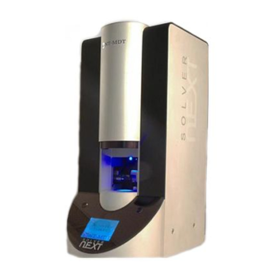
- Page 1 SOLVER platform SOLVER NEXT Instruction Manual www.ntmdt-si.com...
- Page 3 Scanning Probe Microscope Solver NEXT Instruction Manual 2011 - 2018, Copyright © NT-MDT SI NT-MDT Spectrum Instruments Proezd 4922, 4/3 Zelenograd, Moscow 124460, Russia Tel.: + 7 (499) 110-2050 www.ntmdt-si.com...
- Page 5 Read me First! Observe safety measures for operation with devices containing sources of laser radiation. Do not stare into the beam. A label warning about the presence of laser radiation is attached to the laser sources (Fig. 1). Fig. 1 Before you start working with the instrument, get acquainted with the basic safety measures and the operation conditions for the instrument! If you are a beginner in scanning probe microscopy, we recommend you to familiarize with...
- Page 7 User’s documentation set The following manuals are included into the user’s documentation set: - Instruction Manual – is the guidance on preparation of the instrument and other equipment for operation on various techniques of Scanning Probe Microscopy. The contents of the user’s documentation set may differ depending on the delivery set of the instrument.
-
Page 9: Table Of Contents
Table of Contents Solver Next Scanning Probe Microscope. Instruction Manual Table of Contents OVERVIEW .............................. 5 1.1........................... 5 PECIFIC EATURES 1.2.............................. 6 ESIGN 1.3................8 OSITIONING THE UILT EASURING EADS 1.4. - Page 10 Solver NEXT SPM. Instruction Manual 7.1.4. Contact Error Mode ......................76 7.1.4.1. Brief Description of the Mode ....................76 7.1.4.2. Preparation for Measurements ....................77 7.1.4.3. Scanning ..........................77 7.1.5. Piezoresponse Force Microscopy ..................78 ...
- Page 11 Table of Contents 7.5.3.1. Configuring and Making Measurements ................156 7.6. STM S ......................... 159 PECTROSCOPIES 7.6.1. Current Imaging Tunneling Spectroscopy I(V) ..............159 7.6.2. I(Z) Spectroscopy ......................161 LITHOGRAPHY ..........................163 ...
- Page 12 Solver NEXT SPM. Instruction Manual...
-
Page 13: Overview
Microscopy; Spreading Resistance Imaging; Nanosclerometry; AFM Lithography (Current), STM Lithography. 1.1. Specific Features The key distinction of the Solver NEXT SPM from its analogues is availability of two built-in measuring heads (AFM and STM) that are automatically adjusted to their working position. -
Page 14: Design
Solver NEXT SPM consists of the following main units: Solver NEXT measuring unit; ● SPM controller; ● Computer. ● Besides, the delivery set of the Solver NEXT SPM can be optionally extended with: Measuring head for liquid environment; ● Liquid cell; ● Measuring head of the nanoindenter; ●... - Page 15 The optical microscope of this system is equipped with a positioning system that provides selection of the scan area on the sample surface. The Solver NEXT measuring unit is equipped with two measuring heads, for atomic-force microscopy (AFM) and for scanning tunneling microscopy (STM). Availability of two built-in measuring heads enables quick exchange of the experimental technique and does not need special training of the operator.
-
Page 16: Ositioning The Built - In
Solver NEX XT SPM. Instr ruction Manu 1.3. P Position ning the Built-in n Measu uring He eads The built-i in measuring g heads are located ins side the SPM M body. The ey can stay in one of tw basic statio onary positi ons (see Fig... -
Page 17: Heads
Chapter 1. Overview 1.4. Technical Specification Measuring system Built-in measuring heads AFM, STM Mountable measuring heads liquid, nanosclerometric System for detecting the cantilever automated alignment deflection Laser wavelength of cantilever 850 nm deflection system Sample Size up to ø20×10 mm Positioning range, in XY plane 5×5 mm Positioning method... - Page 18 Solver NEXT SPM. Instruction Manual Optical viewing system Positioning range, 5×5 mm 0.3 μm Positioning step 2 μm Resolution 3.4 ÷ 0.53 μm Field of view Dimensions and weight Overall dimensions 320×215×470 mm Weight 30 kg Power characteristic Voltage 110/220 V...
-
Page 19: Basic Safety Measures
● Do not disassemble any part of the device. Disassembling of the product is permitted ● only to persons certified by NT-MDT. Do not connect additional devices to the instrument without prior advice from an ● authorized person from NT-MDT. - Page 20 Solver NEXT SPM. Instruction Manual Laser Observe safety measures for operation with devices containing sources of laser ● radiation. Do not stare into the beam. A label warning about the presence of laser radiation is attached to the rearing panel of the measuring unit.
-
Page 21: Operating Conditions
Chapter 3. Operating Conditions 3. Operating Conditions The SPM should be installed in a room of total area larger 6 sq. meters with range of purity better 8 (by ISO 14644-1-2002). To provide for the qualitative and safe operation of the instrument, it is recommended to observe the following conditions: environment temperature: ●... - Page 22 Solver NEXT SPM. Instruction Manual the table intended for installation of the instrument measuring unit must be stable and, ● whenever possible, massive; to provide solid stability against vibrations, SPM modules should be placed on self- ● leveling floor with marble covering alongside bearing components of the building (pillows, beams etc.);...
-
Page 23: Regulations On Packaging, Storage And Transportation
Chapter 4. Regulations on Packaging, Storage and Transportation 4. Regulations Packaging, Storage Transportation Packaging of the equipment should be performed indoors in a ventilated room at ● ambient temperature of 15° С – 40 °С and relative humidity at most 80 % with no corrosive agent in the atmosphere. -
Page 24: Setup And Installation
Solver NEXT SPM. Instruction Manual 5. Setup and Installation 5.1. Connecting the Electromechanical Units ATTENTION! Before connecting or disconnecting any unit, switch off the controllers. Disconnecting or connecting cables while the devices are operating may cause damage to their electronic circuits. -
Page 25: Installing Software
Chapter 5. Setup and Installation 5.2. Installing Software Nova P9 program doesn't need special installation procedure. Just insert the software CD- ROM in the computer CD-drive and copy the content of Nova P9 folder to the desired location of your hard drive. With the program installed, install drivers of the scanning probe microscope controller. - Page 26 Solver NEXT SPM. Instruction Manual Fig. 5-3 c) For defining the desired path, select the options Search for the best driver in these location and Include this location in the search and then click the Browse button. Fig. 5-4 d) The dialog will open.
- Page 27 Chapter 5. Setup and Installation Browse For Folder Fig. 5-5. window Fig. 5-6. Installing the controller's driver e) When installing the drivers of the hardware completes, click the USB <-> Serial button. The installation wizard will close. Finish...
- Page 28 Solver NEXT SPM. Instruction Manual Fig. 5-7 2. With the drivers of the hardware installed, the operating system will USB <-> Serial find another hardware, , and open the USB Serial Port Found New Hardware Wizard dialog again. Found New Hardware Wizard Fig.
- Page 29 Chapter 5. Setup and Installation b) The installation wizard will ask how to find location of drivers on your computer. Select the option that allows for manual Install from a list or specific location defining the path of drivers location. Click the button.
- Page 30 Solver NEXT SPM. Instruction Manual Browse For Folder Fig. 5-11. window e) The window will open to inform that the tested hardware is Hardware Installation incompatible with the operating system. Click the button. This Continue Anyway will start installing the driver of the controller's USB port.
- Page 31 Chapter 5. Setup and Installation Fig. 5-13. Instaiing the driver of the controller's USB port f) When installing the drivers of the hardware completes, click the USB Serial Port button. The installation wizard will close. Finish Fig. 5-14...
-
Page 32: Powering Sequence
Solver NEX XT SPM. Instr ruction Manu 5.3. P Powerin g Sequ ence Switching 1. Turn th he computer r on. 2. Turn th he vibration n protection system on. 3. Turn on n the SPM c controller. ATTEN NTION! Al l connector rs should b be tightened... -
Page 33: Calibrating The Stepper Motors
Chapter 5. Setup and Installation 5.4. Calibrating the Stepper Motors Stepper motors of the instrument should be calibrated after installation of equipment and/or control software as well as after repairing malfunction of the instrument (e.g., caused by power failure). panel provides controls of all instrument modules that contain stepper Next Motors motors. - Page 34 Solver NEXT SPM. Instruction Manual a) Control window for one motor b) Control window for two motors Fig. 5-16. Stepper motors control window 2. Switch to the tab (Fig. 5-17). Controls...
- Page 35 Chapter 5. Setup and d Installation a) Control w window for on ne motor Control wind dow for two m motors ig. 5-17. Ste pper motors control wind dows. Calibra ation tab Start the calibration procedure with the button. T The gear of the stepper motor wi...
- Page 36 Solver NEX XT SPM. Instr ruction Manu Fig. 5-18. M essage wind 5. Apply calibration to all stepp er motors o of the instrum ment.
- Page 37 apter 6. Prep paring for Me easurements 6. Prep paring for Me easurem ments his chapter explains th he preparat tory proced dures requir red for AFM M measurem ments. The equence of t those proced dures includ des the follo owing steps Turning O On (see sect...
- Page 38 Solver NEX XT SPM. Instr ruction Manu 6.2. M Mountin g the S ample A sample to study is mounted o n a standar rd metal sub bstrate (see Fig. 6-2) d delivered wi the instrum ment. . 6-2. Standa ard metal sub bstrate If thicknes...
-
Page 39: Preparing For Measurements
Chapter 6. Preparing for Measurements 3. Place the sample-substrate assembly on the scanner magnetic fastener (see Fig. 6-6). Fig. 6-6. Sample-substrate assembly placed on the scanner magnetic fastener Mounting the sample on a substrate with the spring contact For measurements requiring electrical contact between the sample and the instrument, it is recommended to use a specialized substrate equipped with the spring contact (see Fig. - Page 40 Solver NEXT SPM. Instruction Manual 3. Place the sample-substrate assembly on a standard metal substrate (see Fig. 6-9). Fig. 6-9. Sample-substrate assembly placed on a standard metal substrate 4. Place the assembly of the sample and the two substrates on the scanner magnetic fastener.
-
Page 41: Scanner
apter 6. Prep paring for Me easurements Fig. 6-11 . Calibration n parameters s dialog 6.3. Se electing erating Scanner CANSCA CALER™ ™ System he SCANSC CALER™ s system prov vides measu urement in o one of the tw wo followin ng modes: "high vol ltage"... -
Page 42: Robe
Solver NEX XT SPM. Instr ruction Manu 6.4. In nstalling g the Pr robe ATTEN NTION! B Before inst talling/exch hanging th he probe, the scann magnet tic fastener r should be e placed at its lowest extreme fo or the samp not to p prevent mo ovement of... - Page 43 Chapter 6. Preparing for Measurements Fig. 6-13 Fig. 6-14 3. Release the probe clip spring by turning downward the trapezoidal lever, located on the outer side of the holder body, with a tweezers (see Fig. 6-15). Fig. 6-15 Fig. 6-16 4.
- Page 44 Solver NEXT SPM. Instruction Manual translation with the tweezers Fig. 6-17 Fig. 6-18 6. Move the probe with the tweezers to the working position (see Fig. 6-19) as shown schematically in Fig. 6-18. The probe at its working position is shown in Fig. 6-20.
-
Page 45: Installing The Stm Tip
Chapter 6. Preparing for Measurements Fig. 6-21 Fig. 6-22 AFM probe is now installed. NOTE. If the AFM probe is not planned to work after installation, it is recommended to withdraw it to its inoperative position by clicking the button on the Measuring heads control panel (see Fig. - Page 46 Solver NEXT SPM. Instruction Manual ATTENTION! Do not use the wire cutting scissors for other purposes. Fig. 6-23 Apex forming procedure includes the following steps: 1. Clamp the wire with the tweezers so that it projects beyond its edge for 2÷3 mm (see Fig.
- Page 47 apter 6. Prep paring for Me easurements nstalling th he Tip into t the Holder Use of two tw weezers ena ables installi ing the STM M tip into th he holder. o install or exchange th he STM tip, , perform th he following g steps:...
- Page 48 Solver NEX XT SPM. Instr ruction Manu 5. Release e the spring g. Make sure e that the tip p is fixed fir rmly in the holder. NOTE. Tip sharp pness and fi firmness of the tip fixa ation in the e clamp are e the prima factors...
-
Page 49: Protective Shield (Isoshield System™)
Chapter 6. Preparing for Measurements a) AFM head b) STM head Fig. 6-30. Measuring head at its working position 6.6. Screening with Protective Shield (ISOSHIELD SYSTEM™) To activate screening with the protective shield, click the button in the Measuring heads control panel (see Fig. 6-31). This draws down the protective shield that covers the measuring head and the sample to reduce exposure of the measurement system to external noises thus improving conditions for scanning. -
Page 50: Adjusting The Cantilever Deflection Detection System In Automatic Mode (Expertfba™ System)
Solver NEXT SPM. Instruction Manual NOTE. The laser for detecting the cantilever deflection is kept off while the protective shield is lifted. The laser is activated automatically after the shield is drawn down. Two modes are provided for adjusting the cantilever deflection detection system: Automatic mode (see sect. - Page 51 apter 6. Prep paring for Me easurements In the mo odes drop-d down list of panel, selec . This defines the Laser/P Photodiode default se earch region n for the can ntilever in a air. In the field of the nel, define the thresho old for the...
- Page 52 Solver NEX XT SPM. Instr ruction Manu Actually, a aiming the l laser is prec ceded by co ollecting the e distributio on of the re eflected sign over the p predefined r region. Thi is acquisitio on is perfo rmed autom matically, w with the las...
- Page 53 Chapter 6. Preparing for Measurements Viewer Fig. 6-35. panel 1 – boundary of the selected search region; 2 – cursor pointing to the laser beam position b. Move and/or resize the search area with the mouse (see. 1 on Fig. 6-35). 4.
- Page 54 Solver NEXT SPM. Instruction Manual Fig. 6-36. 2D Viewer 1 – laser spot from the cantilever; 2 – laser spot from the chip For repositioning the photodiode, click the button of the window or the button of the stepper motor control panel to...
- Page 55 Chapter 6. Preparing for Measurements Diode mover Fig. 6-37. window. Photodiode position control tab 7. Repeat acquisition of the laser spot intensity distribution over a small region around the previously found position of the spot by clicking the button. This provides more precise profile of the distribution over the narrowed region that is displayed in the 2D Viewer (see Fig.
- Page 56 Solver NEX XT SPM. Instr ruction Manu ig. 6-38. Prof file of the las ser spot after r repeated se earch To aim the e laser beam m at the prob be cantileve er, perform t the followin ng steps: 1.
- Page 57 apter 6. Prep paring for Me easurements o aim the la aser spot at t the cantilev ver with mor re precision n, perform th he followin ng steps: Open the window w (see Fig. 6 6-39) by clic cking the button in Laser mov window.
- Page 58 Solver NEX XT SPM. Instr ruction Manu window c ontains a 2 2D Viewer s showing im mage of the laser spot aser Aiming the pho otodiode sec ctions (left) and a table e of current levels of th e photodiod de outputs.
- Page 59 apter 6. Prep paring for Me easurements Fig. 6-42. Las ser spot cen tered at the photodiode he procedu ure on autom matic align nment of th e photodiod de complet tes with the e laser spot entered at th he photodio de and relea ases the...
-
Page 60: Initial Approach
Solver NEX XT SPM. Instr ruction Manu NOTE. During th e initial ap pproach kee ep the prote ective shiel ld lifted to enable visu inspect tion of the probe-surfa face distanc ce. Draw do down the pr rotective sh hield after t initial a approach (s... - Page 61 apter 6. Prep paring for Me easurements Fig. 6-45. Ad djusting dialo og of the vide eo camera Define th he frame ra te of the vi ideo camera a to be 30 Hz by selec cting this v value in the list.
- Page 62 Solver NEXT SPM. Instruction Manual 6. Open the Control window of the sample movement stepper motors by clicking the button (see Fig. 6-47). Fig. 6-47. Control window of the sample movement stepper motors 7. Use buttons of the panel to move the sample so that the desired area Controls XY comes under the tip.
-
Page 63: Selecting The Scan Area (Pinpoint™ System )
Chapter 7. Performing Measurements 7. Performing Measurements 7.1. Contact AFM 7.1.1. Constant Force Mode Operations performed in measurements of surface topography with the Constant Force Mode have much in common with those of other contact techniques, including the Lateral Force Mode, the Spreading Resistance Imaging Mode, the Force Modulation Mode, and the Contact Error Mode. -
Page 64: Adjusting The Controller Configuration
Solver NEXT SPM. Instruction Manual 7.1.1.1. Adjusting the Controller Configuration Switch the instrument for operating in the Contact technique by selecting in the Contact controller configuration list (see Fig. 7-1) at the top bar of the Main Program window. Fig. 7-1. Selecting the controller configuration... - Page 65 Chapter 7. Pe erforming Me easurements Fig. 7-2. Las ser spot cent tered at the p photodiode n completio on of adjust ting the pho otodiode, the utton release Adjusting in nitial level o of the DFL signal man nually Open the window (see Fig.
- Page 66 Solver NEX XT SPM. Instr ruction Manu 2. Watch position of f the laser s spot in the window (see Fig. 7 -2) and mo Laser Aimin the spo ot with the b buttons of t panel (see e Fig. 7-3) s so that the s spot is halv Controls...
- Page 67 Chapter 7. Pe erforming Me easurements Start the approach p procedure w with the utton in the e Control p panel of the window (s see Fig. 7-5 Approach Approa Fig. 7-5. Con ntrol panel of f the window uring the a approach p procedure, o observe var...
- Page 68 Solver NEX XT SPM. Instr ruction Manu The si gnal increases t to the leve el of param meter, the fe feedback lo Set P oint ● mainta ins the Z-sc canner in th he position w where the value is s equal to .
- Page 69 Chapter 7. Pe erforming Me easurements or stable op peration, it i is recomme ended to de fine the fee edback gain n to less 0.5 5÷0.7 of the hreshold val lue where t the noise ge eneration o occurs. The feedback g gain is adju usted in the...
- Page 70 Solver NEX XT SPM. Instr ruction Manu 7.1.1.5. Adjus ting Sca nning Pa arameter Open the indow by cl licking the button in the e Main Oper rations pane Scanning The top pa art of the window con ntains a pan nel to contr rol the scan nning proce...
- Page 71 Chapter 7. Pe erforming Me easurements electing the e scan area o choose preliminar ry dimensi ons of th he scan ar rea, regard d for the following ecommenda tions: If height difference i in the surfac ce profile is s known to b be within th he Z-scanne...
- Page 72 Solver NEX XT SPM. Instr ruction Manu 2. In the d drop-down list (see po os. 3 on Fig . 7-12), sele ect between n the modifi ication mod . This mode es define ho ow the param meters will Hold Change Area...
- Page 73 Chapter 7. Pe erforming Me easurements witching th he detection n signals he measurin ng modes a are associat ted with is standard de etection sig gnals that ar re assigned utomatically y after the m mode has b been selecte ed.
- Page 74 Solver NEX XT SPM. Instr ruction Manu 7.1.1.6. Scann ning Hereafter, the scannin ng process w will be expla ained with t the example e of a rectan ngular grati (standard g grating TGQ Q-1, 3 μm re esolution). Starting m measuremen Scanning o of the samp...
- Page 75 Chapter 7. Pe erforming Me easurements If the button in th he left bott tom of the 2D Viewer r of the sca an data is p pressed, the ● 1D Viewe er will disp lay the dete ection signa l in real tim me (see Fig.
- Page 76 Solver NEX XT SPM. Instr ruction Manu Fig. 7-20. Surfac ce topograph y image With the c correction d defined, the e 1D Viewe er of the sc can data w will display the detecti signal cor rrected for the tilt co ontribution.
- Page 77 Chapter 7. Performing Measurements Fig. 7-22 Fig. 7-23 button serves to restart scanning again. Restart NOTE. Scanning is recommended to restart (using the Restart button) after any of scanning parameters is changed. Some recommendations on optimization of scanning parameters The choice of the optimal value of scanning speed depends on properties of the sample, on dimensions of the scan area, and on external conditions.
- Page 78 C Choose a f folder to st tore the dat ta (the def fault folder C:\Prog gram Files\N NT-MDT\N Nova_9). 4. Type in n a filename e and save i it with the e extension *. mdt. NOTE.
- Page 79 Chapter 7. Performing Measurements 7.1.2. Lateral Force Microscopy 7.1.2.1. Brief Description The Lateral Force Microscopy facilitates discrimination between areas with different coefficients of friction as well as reveals specific features of surface topography. This mode is useful in research of semiconductors, polymers, film coatings, memory media for physico-chemical properties of the surface (in particular, deterioration), tribology characteristics etc.
-
Page 80: Approaching The Sample To The Probe
Solver NEXT SPM. Instruction Manual 7.1.2.2. Procedural Sequence Procedures of the Lateral Force Mode are based on those of the Constant Force Mode that is described in detail in sect. 7.1.1 “Constant Force Mode” on p. 55. Main procedures involved in the Lateral Force Mode 1. -
Page 81: Spreading Resistance Imaging
Chapter 7. Performing Measurements Fig. 7-28. Images of surface topography and distribution of lateral forces 7.1.3. Spreading Resistance Imaging 7.1.3.1. Brief Description The Spreading Resistance Imaging mode is a very efficient AFM mode. It is employed in various fields, including defects in conductive and low conductive films, materials characterization in terms of local resistance etc. -
Page 82: Procedural Sequence
Solver NEXT SPM. Instruction Manual 7.1.3.2. Procedural Sequence Procedures of the Spreading Resistance Imaging Mode are based on those of the Constant Force Mode that is described in detail in sect. 7.1.1 “Constant Force Mode” on p. 55. Before starting the Spreading Resistance Imaging, make preparations for measurements and perform measurements of surface topography by the Constant Force Mode Remember to use the measuring head equipped with the conducting contact probe. -
Page 83: Scanning
Chapter 7. Pe erforming Me easurements IprAFM Oscilloscope Fig. 7-30. S Selecting the gnal in the window Enter the e probe-sam mple bias vo oltage in th input field of th he top bar o of the Main program window. A Adjust the bias volt tage so that... -
Page 84: Contact Error Mode
Solver NEXT SPM. Instruction Manual How to Improve Image Quality ATTENTION! Too tight mechanical contact between the probe and the sample may cause damage to the conductive coating of the probe. If necessary, you can try the following recommendations: Adjust the parameter (it controls pressure applied to the sample by the probe);... -
Page 85: Preparation For Measurements
Chapter 7. Performing Measurements 7.1.4.2. Preparation for Measurements The Contact Error Mode is based on the Constant Force Mode, which is described in detail in i. 7.1.1 “Constant Force Mode” on page 55. Before the Contact Error Mode measurements, prepare for the measurements and perform measurements of surface topography by the Constant Force Mode. -
Page 86: Brief Description Of The Mode
Solver NEX XT SPM. Instr ruction Manu Erro Fig. 7-33. Images s of surface topography a and the signal If the button in the left bot tom of the w window is p pressed, the e 1D Viewe er will displ ●... - Page 87 Chapter 7. Performing Measurements Fig. 7-35 illustrates displacements of the structure whose domains are oriented both vertically and horizontally. The case of the altering electric field is considered. Oscillations of the surface are shown both for the positive direction of the electric field, above, and for the negative, below.
-
Page 88: Preparation For Measurements
Solver NEXT SPM. Instruction Manual Fig. 7-36 However interpretation of the results obtained is not always simple. It is necessary to consider a number of factors which can affect or influence images obtained during measurements. For better signal (oscillation amplitude), it is desirable to operate on a frequency that is close to the frequency of the system cantilever-probe-surface (so that oscillations of the cantilever pressed to the sample would be resonance). -
Page 89: Adjusting Scanning Parameters
Chapter 7. Performing Measurements 7.1.5.3. Adjusting Scanning Parameters 1. Open the scanning window with the button in the Main Operations panel. 2. Choose the mode from the list on the control panel of the scanning Contact PFM Mode window (Fig. 7-37). This results in automatic performing all necessary switching sequences in the controller. -
Page 90: Scanning
Solver NEXT SPM. Instruction Manual 7.1.5.4. Scanning Click the button , which is on the control panel of the tab, to trigger the process Scan of scanning. The following actions take place: Line-by-line scanning of the sample surface starts and three images appear in the field ●... - Page 91 Chapter 7. Performing Measurements Fig. 7-41 After switching the inputs of the lock-in amplifier and the phase detector from the second image of the scanning 2D data visualizes the distribution of the lateral oscillations amplitude, while the third image is the distribution of lateral phase (Fig. 7-42). Fig.
-
Page 92: Semicontact Afm
Solver NEXT SPM. Instruction Manual 7.2. Semicontact AFM 7.2.1. Semicontact Mode Operations performed in measurements of surface topography with the Semicontact Atomic Force Microscopy of different modes have much in common with those of other techniques based on resonant oscillations of the cantilever. - Page 93 Chapter 7. Pe erforming Me easurements 7.2.1.1. Adjustin ng the Co ontroller r Configu uration witch the in nstrument fo for operating g in the Co ntact techni ique by sele ecting miContact he controller r configurat tion list (see e Fig.
- Page 94 Solver NEXT SPM. Instruction Manual Fig. 7-44. Piezodrive adjustable parameters panel NOTE. To display frequency responses of the signals Mag and Phase , select the corresponding options in the Settings subgroup of the Manual parameters group: Signal 1 Signal 2 Phase.
- Page 95 Chapter 7. Pe erforming Me easurements Resona ance g. 7-45. Con trol panel of window 4. To start a automatic a djustment o of the piezo odrive param meters, click k the button in the panel (se ee Fig. 7-45 5).
- Page 96 Solver NEX XT SPM. Instr ruction Manu Adjusting generator parameter rs manually 1. Open t windo ow by clic king the button in the Ma Resona ance Operat ions panel. 2. In the d drop-down list of the panel, select the d desired type e of the prob Find Resona...
- Page 97 Chapter 7. Pe erforming Me easurements Adjust th he desired le evel of the signal l. This can be done eit ther with ad djusting the generator r voltage ( parameter in n the subgroup of f the group) Amplitude Hardw ware or with ad...
- Page 98 Solver NEXT SPM. Instruction Manual Approach Fig. 7-49. Control panel of the window During the approach procedure, observe variations of the signal in the software oscilloscope and state of the scanner extension indicator. Wait until the procedure completes. Providing the approach parameters are set correctly, the approach procedure completes in about 10 to 30 seconds and the system goes to following state (see Fig.
- Page 99 Chapter 7. Pe erforming Me easurements signal de ecreases to the level of paramet , the feed dback loop Set Poin ● maintains s the Z-scan nner in the position wh here the va alue of is equal to Set Point Note that t this positi ion of the...
-
Page 100: Adjusting Scanning Parameters
Solver NEXT SPM. Instruction Manual For stable operation, it is recommended to define the feedback gain to less 0.5÷0.7 of the threshold value where the noise generation occurs. The feedback gain is adjusted in the input field. Gain To adjust the working level of the feedback gain, perform the following steps: 1. - Page 101 Chapter 7. Pe erforming Me easurements Scan nning . 7-54. window he bottom o of the wind dow contain ns a Viewer r to display y topography y of the sur rface under nvestigation electing AF FM mode elect the mode e in the list of t...
- Page 102 Solver NEX XT SPM. Instr ruction Manu parame eters, includ ding speed o of scanning Then the sca an area can Set Point FB Gain enlarge To select o or to resize t the scan are ea, perform the followin ng steps: 1.
- Page 103 Chapter 7. Pe erforming Me easurements Select the e parameter r that will be fixed or r linked un nder adjustm ment (accor rding to the modificat tion mode, p pos. 3) with h the selecto or (pos. 2). Adjust th he paramet define the e scan area...
- Page 104 Solver NEX XT SPM. Instr ruction Manu column di isplays sign nals to det ect during the sampl e moves in n the forw ward scanni direction w while the lumn enlists s signals for r the backw ard movem ment.
- Page 105 Chapter 7. Pe erforming Me easurements 7.2.1.6. Scannin Hereafter, the e scanning p process wil l be explain ned with the e example o of a rectangu ular grating standard gra ating TGQ-1 1, 3 μm reso olution). tarting mea asurements canning of the sample...
- Page 106 Solver NEX XT SPM. Instr ruction Manu If the button in n the left bo ottom of th he 2D View wer of the s scan data is s pressed, t ● 1D Vie ewer will di isplay the de etection sign nal in real t time (see Fi...
- Page 107 Chapter 7. Pe erforming Me easurements Fig. 7-6 64. Surface t topography im mage With the cor rrection def fined, the 1 1D Viewer of the scan n data will display th he detection gnal correc cted for th he tilt cont ribution.
-
Page 108: Saving Measurement Data
Solver NEXT SPM. Instruction Manual Fig. 7-67 NOTE. Scanning is recommended to restart (using the Restart button) after any of scanning parameters is changed. Some recommendations on optimization of scanning parameters The choice of the optimal value of scanning speed depends on properties of the sample, on dimensions of the scan area, and on external conditions. - Page 109 Chapter 7. Pe erforming Me easurements 7.2.1.8. Comple eting Mea asureme o complete operation, p perform the e following steps: Open the feedback lo oop by relea asing the utton. Retract th he sample fr rom the pro obe through the followi ng steps: a.
-
Page 110: Semicontact Error Mode
Solver NEXT SPM. Instruction Manual 7.2.2.2. Preparation for Measurements The Semicontact Error Mode is based on the Semicontact Mode, which is described in detail in i. 7.2.1 “Semicontact Mode” on page 84. Before the Semicontact Error Mode measurements, prepare for the measurements and perform measurements of surface topography by the Semicontact Mode. - Page 111 Chapter 7. Pe erforming Me easurements g. 7-70. Imag es of surface e topography y and the signal (TG GQ-1 grating The pane l of 1D ima ages visualiz zes the sign nal measured d line-by-lin ne (Fig. 7-7 71). ●...
- Page 112 Solver NEXT SPM. Instruction Manual The phase shift distribution over the sample surface visualizes distributions of characteristics of the sample substance. The Phase Imaging Mode yields valuable information for a broad area of applications. In some cases it can uncover hidden contrasts in materials properties. This modeis employed, for example, in the study of biological objects, samples with electrical and magnetic properties and a number of other areas.
-
Page 113: Modes Of Improving Image Quality
Chapter 7. Pe erforming Me easurements Fig. 7-74. Image es of surface e topography and phase d distribution o of polyethylen If the button in the e left bottom m of the wi indow is pre essed, the 1 D Viewer w will display ●... -
Page 114: Many-Pass Afm Techniques
Solver NEXT SPM. Instruction Manual 7.3. Many-Pass AFM Techniques This chapter assumes the reader is experienced in performing measurements with NT- MDT instruments using techniques of contact and semicontact atomic force microscopy. In general many-pass techniques are used in tasks where other than topography data are to be obtained at that topography unwanted side effects must be eliminated. -
Page 115: Procedural Sequence
Chapter 7. Performing Measurements Then, the probe is lifted above the surface to the height dZ. In the second pass, the probe moves over the surface along the same line following the surface topography contour (see Fig. 7-77) maintaining the surface-probe distance constant. This distance should be big enough to eliminate the surface topography influence. -
Page 116: Adjusting Scanning Parameters
Solver NEXT SPM. Instruction Manual NOTE. The magnetic probes may become demagnetized after long-term storage. Before using a probe, magnetize it with a permanent magnet. Initial state The following steps are assumed to be done: Launching the control program; ●... -
Page 117: Scanning
Chapter 7. Pe erforming Me easurements 7.3.1.4. Scannin Hereafter, th he scanning process w will be expla ained with the exampl le of a har d magnetic isk. tarting mea asurements canning of the sample e surface sh hould be pre eceded by n necessary p preparation... -
Page 118: Kelvin Probe Microscopy
Solver NEX XT SPM. Instr ruction Manu butto on becomes enabled an nd caption of the button cha anges to estart ● (see Fig g. 7-81). Scan nning Fig. 7-81. C Control panel of the window w in the cour rse of scanni Should the e scanning p... - Page 119 Chapter 7. Performing Measurements The value of the ac component, U ·sin(ωt), of the bias voltage should be big enough to induce oscillations of the probe. Frequency of the ac electric field is selected to be equal to the resonance frequency of the probe. Once amplitude of the oscillation becomes zero at some value of the dc bias, this voltage is equal to the local surface potential.
-
Page 120: Procedural Sequence
Solver NEXT SPM. Instruction Manual During the second pass the distance between the scanned surface and the probe is kept constant. This distance should be big enough to eliminate the surface topography influence. In this case, the probe is only affected by long-range forces whose most prominent yield is due to electric properties of the sample. - Page 121 Chapter 7. Pe erforming Me easurements esides, you u have to pe erform a pr reliminary s scan of the sample in t the Semico ontact mode see sect. 7.2 2.1 “Semico ontact Mode e” on p. 84 4) and then to select th he scan are ea for SKM...
- Page 122 Solver NEX XT SPM. Instr ruction Manu Fig. 7-8 85. Block dia agram of the instrument b. In t list, sel lect to edit para ameters of th he second p pass. Show St tate Pass II c. Op en the feedb back loops o on Z and on n U (the...
- Page 123 Chapter 7. Pe erforming Me easurements Fig. 7 7-87. Spectro oscopy wind In the drop p-down list, select. This will r result in: ectroscopy Mode g(BV) SKM select ting the signals as measure ed signals in the asurements ● panel select ting the as t...
-
Page 124: Scanning
Solver NEXT SPM. Instruction Manual Mag(BV) Fig. 7-88. relation at a point If the plot of the relation is "V-shaped" (has a pronounced peak) (see Fig. 7-88), Mag(BV) the instrument operates properly. Now, measurements on Kelvin Probe Microscopy can be performed. - Page 125 Chapter 7. Pe erforming Me easurements his results i n the follow wing activity y of the sys tem: Line-by-l line scannin ng of the sa ample surfa ace starts an nd three im mages of the e scan area ●...
- Page 126 Solver NEX XT SPM. Instr ruction Manu How to im mprove the image When the SKM mod de is select ted, the pa arameters o f the secon nd pass are e set to th defaults. T The acquired d image can n be improv ved with ru un-time adju...
- Page 127 Chapter 7. Performing Measurements Fig. 7-92. First pass Surface topography imaging Then, in the second pass, the probe is lifted above the surface at the height dZ. The piezodriver induces oscillations of the probe at its resonance frequency and a dc bias voltage U is set between the probe and surface.
-
Page 128: Electric Force Microscopy
Solver NEXT SPM. Instruction Manual 7.3.3.2. Preparation for Measurements To operate in the Electric Force Microscopy Mode a sample should be glued to the substrate with the conductive glue or mounted on the substrate with a spring contact. And it should be used conductive probes for semicontact modes. -
Page 129: Adjusting Scanning Parameters
Chapter 7. Performing Measurements 7.3.3.3. Adjusting Scanning Parameters Settings of scanning parameters for the EFM Mode differ from those described for the SemiContact Mode only by the scanning mode and by scanning parameters for the second pass. All other settings remain the same. Select the mode (Fig. -
Page 130: Scanning
Solver NEXT SPM. Instruction Manual Fig. 7-95. Block diagram of the instrument. Parameters of the second pass Define the voltage to apply to the probe either in the field of the block Bias Voltage diagram or field in the top bar of the Main Program window. - Page 131 Chapter 7. Pe erforming Me easurements he followin ng actions ta ake place du uring scanni ing: Line-by-l line scannin ng of the sa ample surfa ace starts a nd two ima ages appear r in the 2D ● Scanning g Data View w panel.
- Page 132 Solver NEXT SPM. Instruction Manual Methods of improving image quality When selecting the EFM mode, all parameters required for the second pass are set automatically. To achieve better quality of the images obtained, the values of the following parameters can be varied during scanning: separation between the probe and the surface during scanning in the ∆Z...
-
Page 133: Scanning Tunneling Microscopy
Chapter 7. Performing Measurements 7.4. Scanning Tunneling Microscopy The Scanning Tunneling Microscopy is capable to study surfaces properties of conductive materials with resolution down to atomic scale. The tunnel current recorded during scanning is small enough (0.5 pA ÷ 50 nA) to enable investigating samples with low conductance, biological objects in particular. - Page 134 Solver NEX XT SPM. Instr ruction Manu 7.4.1.1. Adjus ting the Controll ler Config guration Switch the e instrument t for operat ting in the T Tunneling M Microscopy mode by s selecting in the con ntroller conf figuration l list (see Fig g.
- Page 135 Chapter 7. Pe erforming Me easurements Press the button in n the top b bar to close e the feedb back loop. This starts extension n of the Z s scanner to i its maximum m. Progress s of the ext tension is d displayed in the Scann...
- Page 136 Solver NEX XT SPM. Instr ruction Manu Fig. 7 7-104. Intera active Block S Scheme (the necessary s switching is o outlined) c. Clo ose the bloc ck scheme w window by clicking th button n at the rig ght of the ti r of the window.
- Page 137 Chapter 7. Pe erforming Me easurements Fig. 7-10 05. Device P Parameters w window Define th parameter i in the input t field at the e top bar. W We recomme end to enter SetPoint value in t the range 0. 4 nA as the e initial leve el of the para...
- Page 138 Solver NEX XT SPM. Instr ruction Manu 9. Start di isplaying th he signal by pressing th button. 10. Start th he approach hing procedu ure with the button in n the Contro ol panel of t window w (see Fig. 7 7-108).
-
Page 139: Adjusting Working Level Of The Feedback Gain
Chapter 7. Performing Measurements Fig. 7-109. Approach Fig. 7-110 7.4.1.3. Adjusting Working Level of the Feedback Gain The greater is the level of the feedback gain ( parameter), the greater is data Gain processing speed in the feedback loop. Nevertheless, at some high level of the feedback gain (let us call it threshold value), the mode of operation of the feedback loop becomes unstable and noise generation occurs. -
Page 140: Adjusting Scanning Parameters
Solver NEXT SPM. Instruction Manual 2. Gradually increase the level and watch the level in the software Gain IProbe oscilloscope. NOTE. The Gain level should be positive in STM mode. 3. Determine the value of the parameter at which noise generation occurs. The... - Page 141 Chapter 7. Pe erforming Me easurements Fig. 7-11 12. Selecting g the Scannin ng Tunneling g Microscopy y Mode electing the e scan area o choose preliminar ry dimensi ons of th he scan ar rea, regard d for the following ecommenda tions:...
- Page 142 Solver NEX XT SPM. Instr ruction Manu select parameter marked wi ith the sele ector (pos. 2 2) will adju ange der modifica ation of the two others proportiona ally to value e of the thir rd paramete Fig. 7- -113.
-
Page 143: Scanning
Chapter 7. Performing Measurements Adjusting the scanning speed Optimal value of the scanning speed depends on sample surface properties, scan area dimensions and external conditions. A smooth surface can be scanned at higher speed than that with uneven topography and large height difference. Low scanning speed (defined by the parameter) is recommended if the surface Rate... - Page 144 Solver NEX XT SPM. Instr ruction Manu Fig. 7-115. . Scan param meters adjust tment window To modify y the list of d detection sig gnals, perfo orm the follo owing steps 1. Open t the Scan p parameters adjustment t window clicking t ScanParam...
- Page 145 Chapter 7. Pe erforming Me easurements 7.4.1.5. Scannin Hereafter, th he scanning g process w will be expl lained with h the examp ple of high hly oriented yrolytic grap phite (HOP PG). tarting mea asurements canning of the sample e surface sh hould be pre eceded by n...
- Page 146 Solver NEX XT SPM. Instr ruction Manu Height Fig. 7-118. sign butto on becomes enabled an nd caption of the button cha anges to estart ● (see Fig g. 7-119). Scan nning Fig. 7-119. C Control pane el of the windo ow in the cou rse of scann...
- Page 147 Chapter 7. Pe erforming Me easurements Fig. 7-1 21. Surface topography i image With the cor rrection def fined, the 1 1D Viewer of the scan n data will display th he detection gnal correc cted for the e tilt contr ribution.
- Page 148 C Choose a f folder to st tore the dat ta (the def fault folder C:\Prog gram Files\N NT-MDT\N Nova_9). 4. Type in n a filename e and save i it with the e extension *. mdt. NOTE.
-
Page 149: Saving Measurement Data
Chapter 7. Performing Measurements 7.5. AFM Spectroscopies This section discusses the spectroscopy curves measurement procedures. Prior to conducting spectroscopy measurements it is recommended to perform a preliminary scan. The measurement procedures for various types of spectroscopy are similar. As an example, this section considers one of the techniques –... - Page 150 Solver NEX XT SPM. Instr ruction Manu 7.5.1.1. Select ting the F Function n to be M Measured To select a a relation to detect , per rform the fo ollowing ste eps: 1. Switch h the instrum ment to ope erate in con ntact modes s by selecti...
- Page 151 Chapter 7. Performing Measurements provides the total increase of the scanner length when the tip is in contact with the sample. This value should be negative. NOTE. For exploratory measurements, recommended values for From and To are in the ranges from 200 to 500 nm and from –100 to –10 nm, respectively. In the course of measurement, the Height value will behave as shown in Fig.
-
Page 152: Selecting Points For Spectroscopy
Solver NEXT SPM. Instruction Manual 7.5.1.2. Selecting Points for Spectroscopy Taking a scan of the sample surface is recommended before collecting spectroscopy. This scan facilitates selection of points for spectroscopy. The desired image frame can be selected from the drop-down list (Fig. 7-127) in the Toolbar. - Page 153 Chapter 7. Performing Measurements Fig. 7-129 – spectroscopy will be taken at vertices of a predefined grid. The desired rectangular Grid area is defined with the mouse. X and Y grid dimensions are defined in corresponding input fields to the right from the drop-down list (Fig. 7-130). Fig.
- Page 154 Solver NEXT SPM. Instruction Manual Fig. 7-132. Measurement points distributed over a grid 3х3 Parameters selected points collected automatically table. By default, parameters of newly selected points are Custom spectroscopy settings assigned values defined in the Control panel. For modifying measurement parameters of one or several points, perform the following steps: 1) Click the title of the desired point to highlight it.
- Page 155 Chapter 7. Pe erforming Me easurements Custom spectrosco opy settings g. 7-133. Ta 7.5.1.3. Starting g the Mea asureme ents o start meas surements, click the utton in the C Control pan nel of the sp pectroscopy window. Th relati ion will b e collected d at the p...
- Page 156 Solver NEXT SPM. Instruction Manual DFL(Heigth) Fig. 7-134. curve in a point Using a too “soft” cantilever at high humidity may cause “sticking”. If this is the case the curve will look as shown in Fig. 7-135. DFL(Heigth) Fig. 7-135. Spectroscopy curve when the cantilever is “stuck”...
- Page 157 Chapter 7. Pe erforming Me easurements he Viewing g Area prov vides displa aying either of one of t the measure ed curve or r of both of hem. A part ticular appe earance of t the plot can n be adjuste ed with the button in he Toolbar (...
-
Page 158: Calculating Adhesion Force
Solver NEX XT SPM. Instr ruction Manu Imag ge Analysis Fig. 7-137. window 1 – spec ctroscopy fra ame in the Fr rames Tree; 2 – e experimental relation for t the selected measureme nt point; – 2D map; 4 4 –... - Page 159 Chapter 7. Performing Measurements The adhesion force can be calculated assuming the force is a linear function of the probe displacement relative to the sample surface along the Z-axis. By Hooke’s law: = × Δ Height where k – is the cantilever stiffness (see the calibration chart). Δ...
-
Page 160: Saving Measurement Data
Solver NEXT SPM. Instruction Manual Fig. 7-140 In our example of measurements in the Constant Force mode with = 2 nA, the Set Point pressing force is maintained equal to: × ≈ 0.03 / 7.5.1.6. Saving Measurement Data The frame of spectroscopy data is automatically attached to the data file. To save the... - Page 161 Chapter 7. Pe erforming Me easurements or making, t the measure ements com mplete the fo ollowing pro ocedures: Check tha is chos sen in the co ontroller co nfiguration list (Fig. 7- -141). SemiCon ntact Fig. 7-141. S Selecting the controller co onfiguration Open the...
- Page 162 Solver NEX XT SPM. Instr ruction Manu 8. Launch h measurem ments by clic cking the bu utton When the measurem ments comp plete, the Viewing A Area displa ays a plot for the la measureme ent point. A A typical plo ot of the relatio on at a point...
- Page 163 Chapter 7. Performing Measurements Δ Height samples this assumption is fairly realistic. Therefore, the range corresponding to the variation of the signal from its initial level (equal to ) to zero will be Set Point equal to the cantilever oscillations amplitude. As seen from the spectroscopy data, the sloped part of the curve has a region with linear variation of against...
- Page 164 Solver NEX XT SPM. Instr ruction Manu NOTE. It s should be m mentioned th hat the actu ual probe os scillations a amplitude is s independe from the G Gain parame eter specifie ed in the Lo ock-In set of f parameters s on the ins trument blo...
- Page 165 Chapter 7. Performing Measurements Fig. 7-146 The instrument will be automatically reconfigured for the selected measurement mode. 3. Open the spectroscopy window by clicking the button. 4. In the drop-down list, select . This will result in: Spectroscopy Mode I(V) AFM selecting the signal as a recorded signal in the panel;...
- Page 166 Solver NEXT SPM. Instruction Manual Fig. 7-147 Curves of display relations acquired with the argument varying in the range from the From value to the value in forward (red curve) and in backward (blue curve) directions.
-
Page 167: Stm Spectroscopies
Chapter 7. Performing Measurements 7.6. STM Spectroscopies Before performing the STM spectroscopy it is necessary to perform preliminary STM measurements of the investigated area topography (see i. 7.4 “Scanning Tunneling Microscopy” on p. 125). The preparatory and measurement procedures are similar to those discussed in i. - Page 168 Solver NEX XT SPM. Instr ruction Manu 4. In the f fields , de efine the va ariation rang ge of the ar rgument of the measur From relation NOTE. If the Rel l option is s selected in t the drop-do own list of the Argume...
-
Page 169: I(Z) Spectroscopy
Chapter 7. Performing Measurements 7.6.2. I(Z) Spectroscopy I(Z)–spectroscopy uses the relation between the tunneling current ( signal) and IProbe extension of the Z-scanner (parameter Height With the relation between the tunneling current and the distance the scanner tube is extended to, sharpness of the tip can be evaluated. To making measurements, perform the following: 1. - Page 170 Solver NEXT SPM. Instruction Manual I(Z) Fig. 7-151. For high resolution of STM images, the condition ΔZ < 1 nm should be met (sharp drop of current in Fig. 7-151). Violation of this condition implies the tip become blunt and it...
-
Page 171: Lithography
Chapter 8. Lithography 8. Lithography 8.1. Overview This manual is intended for a user experienced in conducting measurements with NT-MDT instruments using contact and semicontact atomic force microscopy and spectroscopy. The Nova P9 program provides three lithography technologies: Force lithography. During the lithography process, the force applied to the sample by ●... -
Page 172: Simple Vector Lithography
Solver NEXT SPM. Instruction Manual 8.1.1.1. Simple vector lithography The Figure below demonstrates a time diagram of the force applied to the sample in the course of the Simple vector lithography (Fig. 8-1). Fig. 8-1. Force applied to the sample in the course of the Simple vector lithography... -
Page 173: Pulse Lithography
Chapter 8. Lithography 8.1.1.3. Pulse lithography The Figure below demonstrates a time diagram of the force applied to the sample in the course of the Pulse lithography (Fig. 8-3). Fig. 8-3. Force applied to the sample in the course of the Pulse lithography. Example of the pulse shape is shown When the probe draws an object of the lithography template, the sample is applied to... -
Page 174: Pulse-Gradient Lithography
Solver NEXT SPM. Instruction Manual 2) Pulse shape . The applied force gets its maximum level A1 instantly and then the force remains constant for the time t. After the time t expires the force returns to the level А0 3) Pulse shape . -
Page 175: Raster Lithography
Chapter 8. Lithography When the probe draws an object of the lithography template, the sample is applied to pressure pulses of varied amplitude. The amplitude varies in a predefined range from A1 to A2. Initial and final levels of the amplitude (A1 and A2) are defined in the fields Action 1 of the Control panel of the window, respectively. -
Page 176: Force Lithography
Solver NEXT SPM. Instruction Manual 8.2. Force lithography Force lithography is based on direct mechanical impact produced by a sharp probe on the sample surface. The probe tip pressure on the surface is sufficient to cause plastic deformation (modification) of the substrate surface. This type of modification has a range of applications in nanoelectronics, nanotechnology, material science, etc. -
Page 177: Preparation For Operation
Chapter 8. Lithography 8.2.1. Preparation for Operation Basic preparatory operations are: 1. Estimation of the Probe Pressure on the Sample (see i. 8.2.1.1 on p. 169); 2. Preliminary Scanning and Selecting Lithography Region (see i. 8.2.1.2 on p. 172). These operations are explained in details below. 8.2.1.1. - Page 178 Solver NEXT SPM. Instruction Manual SpectroForm Fig. 8-7. window 4. In the drop-down list, select . This will append the Spectroscopy Mode Force-Distance list of detected signals of the panel with the signal. Measurement 5. In the fields of the...
- Page 179 Chapter 8. Lithography Fig. 8-8. Approach curve Calculating the force applied to the probe With the spectroscopy data, calculate the force F applied to the probe as: Δ ⋅ Height where ΔHeight is deflection of the cantilever from its equilibrium, and k is rigidity of the cantilever.
- Page 180 Solver NEXT SPM. Instruction Manual To find the probe pressure on the sample, the surface of the probe-sample interaction S is to be estimated. You can use the following equation: π ⋅ where R ≈ 10÷50 nm – is the tip apex radius.
-
Page 181: Vector Lithography
Chapter 8. Lithography Fig. 8-9. Selected region for lithography 8.2.2. Vector Lithography ATTENTION! Before performing vector lithography, lern i. 8.1 «Overview» on p. 163. Initial state: The following preparatory operations are assumed to be done: pressure of the probe onto the sample surface is estimated; ●... -
Page 182: Selecting Lithography Mode
Solver NEXT SPM. Instruction Manual 8.2.2.1. Selecting Lithography Mode To select the lithography mode, perform the following steps: 1. In the controller configuration drop-down list of the Nova P9 program, select Contact (Fig. 8-10). Fig. 8-10. Selecting the controller configuration This will result in automatic configuring the software to operate in contact modes. - Page 183 Chapter 8. Lithography c. Find the level when oscillations starts. This level is featured by a noticeable Gain oscillating component of the input signal. d. Enter the working level to be 0.5÷0.7 of the threshold level of the parameter at Gain which the oscillations starts.
- Page 184 Solver NEX XT SPM. Instr ruction Manu – pulse-gr radient litho ography. Co ombines two o lithograph hy modes, t lse gradient ● lse and the gradient on nes. The sa ample is exp posed to a series of fo orce pulses plitudes var rying in a pr...
- Page 185 Chapter 8. Lithography Fig. 8-17. Template for vector lithography Parameter table of the lithography template Parameter table of the lithography template (Fig. 8-18) is displayed in the window Litho when the option is selected (Fig. 8-19). Primitives list Fig. 8-18. Example of the Parameter table of the Lithography template When a new object is added to the template, the table is appended with a record that contains the name and the parameters of lithography for the new object.
-
Page 186: Adjusting Vector Lithography Parameters
Solver NEXT SPM. Instruction Manual Fig. 8-19. Lithography parameters 8.2.2.3. Adjusting Vector Lithography Parameters Composition of the set of adjustable parameters depends on the selected mode of vector lithgraphy (for details on the vector lithography modes, refer to Chapter 1, i. 8.1.1 «Vector Lithography»). - Page 187 Chapter 8. Lithography Fig. 8-20. Control panel for Simple Vector lithography 2. In the field, define the force applied to the sample when the probe moves to SetPoint starting points of the template objects after finishing drawing or at the start of lithography.
- Page 188 Solver NEXT SPM. Instruction Manual Adjusting Pulse Lithography Parameters 1. In the field of the lithography Control panel, define the force applied to the Action sample during drawing the template objects (Fig. 8-22). Relation between pressure on the sample and the value is given in i.
-
Page 189: Performing Lithography
Chapter 8. Lithography Fig. 8-24. Lithography Control panel 2. In the (Fig. 8-24), define the force applied to the sample when the probe SetPoint field moves to starting points of the template objects after finishing drawing or at the start of lithography. - Page 190 Solver NEXT SPM. Instruction Manual When the procedure completes, the button returns to its initial appearance. Stop The lithography process can be stopped by clicking the button or by pressing the Stop <Esc> key. This will stop the prcess immediately. Next clicking the button would start the lithography procedure from the very beginning, i.e.
-
Page 191: Raster Lithography
Chapter 8. Lithography 8.2.3. Raster Lithography ATTENTION! Before performing raster lithography, learn i. 8.1 «Overview » on p. 163. Initial state: The following preparatory operations are assumed to be done: pressure of the probe onto the sample surface is estimated; ●... - Page 192 Solver NEXT SPM. Instruction Manual 2. Adjust the level for the contact mode as follows: SetPoint a. Break the feedback loop (the button will change its appearance to b. Adjust the level to be 0.5 lower than the current level;...
-
Page 193: Loading Template
Chapter 8. Lithography 5. For Force lithography, select drop-down list (Fig. 8-31). SetPoint in the Method Fig. 8-31. Selecting the lithography method 6. For raster lithography, select in the drop-down list (Fig. 8-32). Raster Mode Fig. 8-32. Selecting the lithography mode 8.2.3.2. -
Page 194: Adjusting Lithography Parameters
Solver NEXT SPM. Instruction Manual 8.2.3.3. Adjusting Lithography Parameters 1. In the Lithography Control panel, define the range of varying the force applied to the sample. Define the lower boundary of the range in the field and the higher Action 1 boundary in the field (Fig. -
Page 195: Performing Lithography
Chapter 8. Lithography 8.2.3.4. Performing Lithography When the lithography template is prepared (see i. 8.2.3.2 on p. 185) and the lithography parameters are adjusted (see i. 8.2.3.3 on p. 186), the operator can start the lithography process. To start lithography, click the button in the Control panel of the window. -
Page 196: Electrical Lithography
Solver NEXT SPM. Instruction Manual 8.3. Electrical Lithography There are two sorts of electrical lithography: Charge lithography. The probe-sample voltage is maintained constant during the ● lithography process; Current lithography. The current through the sample is maintained constant during ●... -
Page 197: Vector Lithography
Chapter 8. Lithography When carrying out electrical lithography, there are two major options of sample surface modification: changing sample topography; ● modifying physical properties of the sample surface without alternating the ● topography. Electrical lithography can be performed in the vector or in the raster mode. This Chapter deals with: 1. - Page 198 Solver NEXT SPM. Instruction Manual Selecting the lithofraphy region for charge lithography Charge lithography will be explained with a GaAs sample and a probe of NSG01/TiN model. Charge lithography will cause accumulation of electrical charge in the subsurface layer under the exposing tip.
-
Page 199: Selecting The Lithography Method
Chapter 8. Lithography Fig. 8-38. Image of the lateral force distribution 8.3.1.2. Selecting the lithography method To select the lithography method, perform the following steps: 1. In the controller configuration drop-down list of the Nova P9 program, select (Fig. 8-39). SemiContact Fig. - Page 200 Solver NEXT SPM. Instruction Manual Litho Fig. 8-40. window 3. In the drop-down list, select the desired mode of lithography (Fig. 8-41): For charge lithography, select Bias V ● For current lithography, select Current ● Fig. 8-41. Selecting the lithography method NOTE.
- Page 201 Chapter 8. Lithography Fig. 8-42. . Selecting th he lithograph hy mode .3.1.3. Creating g Lithogr raphy Te emplate Create a n new lithogr raphy templ late. To this s purpose, c lick the button in t the Toolbar of the Li ithography template (F Fig.
-
Page 202: Adjusting Lithography Parameters
Solver NEXT SPM. Instruction Manual Parameter table of the lithography template Parameter table of the lithography template (Fig. 8-45) is displayed in the Litho window (Fig. 8-19) when the option in the Control panel of the window is Primitives list Litho selected. - Page 203 Chapter 8. Lithography Adjusting Simple Vector Lithography Parameters 1. Decrease the level window by a factor of 2÷10 relatively to the level SetPoint SetPoint used for scanning. 2. In the field of the lithography Control panel, define the exposure level to be Action applied to the sample during drawing the template objects.
- Page 204 Solver NEXT SPM. Instruction Manual Fig. 8-48. Control panel for Charge lithography Fig. 8-49. Control panel for Current lithography 3. In the SetPoint field, define the exposure to be applied to the sample when the probe moves to starting points of the template objects after finishing drawing or at the start of lithography.
- Page 205 Chapter 8. Lithography Fig. 8-51. Control panel for Current lithography 3. In the SetPoint field, define the exposure to be applied to the sample when the probe moves to starting points of the template objects after finishing drawing or at the start of lithography.
-
Page 206: Performing Lithography
Solver NEXT SPM. Instruction Manual Fig. 8-54. Control panel for Current lithography 3. In the SetPoint field, define the exposure to be applied to the sample when the probe moves to starting points of the template objects after finishing drawing or at the start of lithography. - Page 207 Take a scan of the sample by Kelvin Probe Microscopy. Results of electrical lithography can be assessed with the surface potential distribution. For details on scanning, refer to SPM Solver Next. User's Manual. Results of charge lithography Fig. 8-56 shows results of the Simple vector lithography applied to the GaAs sample with = 0 V, = 10 V by the NSG01/TiN probe.
- Page 208 Solver NEXT SPM. Instruction Manual Results of current lithography Fig. 8-57 shows results Simple vector lithography applied octadecyltrichliorsylanum with = 0.3 nA by the DCP 11 probe. Action Fig. 8-57. Sample surface after lithography 8.3.2. Raster lithography ATTENTION! Before performing raster lithography, learn i. 8.1 «Overview»...
- Page 209 Chapter 8. Lithography 8.3.2.1. Preliminary Scanning Selecting Lithography Region Before performing the electrical lithography, take a testing scan in a semicontact mode over the maximum scanning area. NOTE. The preliminary scan can be taken with a contact technique as well, but this can result in noticeable degradation of the conductive layer of the probe tip.
- Page 210 Solver NEXT SPM. Instruction Manual Fig. 8-59. Image of the lateral force distribution 8.3.2.2. Selecting the lithography method To select the lithography method, perform the following steps: 1. In the controller configuration drop-down list of the Nova P9 program, select (Fig.
-
Page 211: Loading Template
Chapter 8. Lithography hlight3 Litho Fig. 8-61. window 3. In the drop-down list, select the desired mode of lithography (Fig. 8-41): For charge lithography, select – Bias V ● For current lithography, select – Current ● Fig. 8-62. Selecting the lithography method 4. - Page 212 Solver NEXT SPM. Instruction Manual Fig. 8-64. Template for raster lithography is loaded 8.3.2.4. Adjusting Lithography Parameters 1. Decrease the level window by a factor of 2÷10 relatively to the level SetPoint SetPoint used for scanning. 2. In the Lithography Control panel, define the range of varying the force applied to the sample.
- Page 213 Chapter 8. Lithography 3. In the field, define the lithography rate (the speed of moving the probe relative to Rate the sample surface). The lithography rate influences on results of the sample exposure to lithography. The lower is the rate, the deeper is the exposure and the better is the correspondence between the template and the resulting surface.
- Page 214 Solver NEXT SPM. Instruction Manual Fig. 8-68. Sample surface after lithography left – topography; right – surface potential distribution Results of current lithography Fig. 8-69 shows results of the raster lithography applied to the octadecyltrichliorsylanum sample with = 0.3 nA, = 0 nA, by the DСP11 probe.
Need help?
Do you have a question about the Solver Next and is the answer not in the manual?
Questions and answers