Table of Contents
Advertisement
Quick Links
Advertisement
Table of Contents

Subscribe to Our Youtube Channel
Related Manuals for BST ekrPro Com60


Summary of Contents for BST ekrPro Com60
- Page 1 BST Web Guiding System ekrPro Com with analog sensors BST International GmbH Heidsieker Heide 53 33739 Bielefeld, Germany Tel: +49 5206/999-0 Fax: +49 5206/999-999 e-mail: info@bst-international.com ekrPro Com web guide controller EDV-No.: MD.191.01.05/1.6.x with analog sensors Date: 23.11.2007...
- Page 2 Symbols used in this operating manual Warning signs Symbols are used in this operating manual in order to clearly indicate particularly important places. Attention! You must obey this type of warning, in order to protect yourself, as the operator, from bodily injuries arising from mechanical movements.
- Page 3 Contents Symbols used in this operating manual Table of contents Section A General information Section B Commissioning Section C Operation Section D Appendix ekrPro Com web guide controller EDV No.: MD.191.01.05/1.6.x with analog sensors Date: 23.11.2007...
- Page 4 ekrPro Com with analog sensors Section A General information Description Specifications Transport / Storage Decommissioning ekrPro Com web guide controller EDV No.: MD.191.01.05/1.6.x with analog sensors Date: 23.11.2007...
-
Page 5: Table Of Contents
Contents Section A General information Symbols used in this manual Table of contents Description A1-1 A 1.1 General information A1-1 A 1.2 Utilisation A1-1 A 1.3 Housing versions A1-1 A 1.4 General definitions A1-2 A 1.4.1 Assignment of sensors to the guiding mode A1-2 selection keys A 1.4.2 Inverting of the sensor signal... -
Page 6: A 1 Description
A 1.2 Utilisation The ekrPro Com is a microprocessor controlled web guiding controller. Together with other BST components it may be used for: • Web edge guiding (right or left) • Web center guiding • Guiding on continuous or interrupted printed lines •... - Page 7 „SENSOR LEFT“ and „SENSOR RIGHT“ respectively. According to the BST definition, the following link applies: SENSOR LEFT = Sensor 1 SENSOR RIGHT = Sensor 2 The following is valid in respect of the sensor mounting positions:...
- Page 8 A 1.4.2 Inverting of the sensor signal If a BST edge sensor, of typical C-design, is mounted according to the BST definition (see section A 1.4.1) as "Sensor left" (sensor 1), then no inversion of the sensor signal is necessary.
-
Page 9: A 1.5 Connectable Components
Description A 1.4.4 Oscillation types and curves An oscillation can be implemented either as a sensor oscillation or an FVG oscillation. In the case of the sensor oscillation, the curve described is a delta function. The FVG oscillation describes a curve in accordance with a sine function. -
Page 10: A 1.6 Safety Information
DIN EN 349 and the industry specific safety regulations must be taken into consideration when installing the BST equipment in the production machine, these include: • There must be a safe distance between the BST equipment and the machinery already installed on-site, such as machine panels, building structure, etc. -
Page 11: A 2 Specifications
Specifications A 2 Specifications A 2.1 ekrPro Com controller (version XT) Power supply 24V DC ± 5% Power consumption 4W (without motor) Input capacitance approx. 950µF Controller inputs 2 x sensors, -9,75 V ...+9,75 V oder 0 V ...+9,75 V 12 bit selectable via software. - Page 12 Specifications Display: LCD graphics module with 128 x 64 pixel and LED background illumination Ambient conditions: Temperature: 0° to 45°C max. Humidity: 5% - 90%, no condensation Weight: approx. 2.1 kg ekrPro Com approx. 2.3 kg ekrPro Com Desk: Case dimensions ekrPro Com (Mounting unit): Installation ekrPro Com Desk (Built-in unit)
-
Page 13: A 2.2 Optical Edge Sensor Ir2001, Ir2005
Specifications A 2.2 A2.2 Optical edge sensor IR 2001, IR 2005 Power supplies: from the controller Measuring range, typical: 12 mm Visual range, typical: 15 mm Output: analog Protection class: IP 54 Ambient conditions: Temperature: 0 to a max. 45 °C Humidity: 5% - 90%, no condensation Case dimensions:... - Page 14 Specifications A 2.5 Ultra-sonic sensor US2003, US2007, US2008 Power supplies: from the controller Measuring range, typical: 15 mm (US 2008 = 4 mm) Visual range, typical: 15 mm (US 2008 = 6 mm) Output: analog Protection class: IP 54 Ambient conditions: Temperature: 0 to a max.
-
Page 15: A 2.8 Reflected Light Measuring Light Barrier R 42 D
Specifications A 2.7 Line sensor T 62 D 1 Power supplies: from the controller Lamp voltage: 5 V; 0.8 A Sensing distance: 15 -30 mm Measuring range: 3 -8 mm Line widths: 0.5 -5 mm Output voltage: 0 to ±10V Protection class: IP 65 Ambient conditions:... - Page 16 Specifications A 2.9 Fork light barrier G 53 C2/5 Power supplies: from the controller Lamp voltage: Fork width: 29 mm Measuring range: ± 3.5 mm Diameter of light beam: 11 mm Protection class: IP 65 Ambient conditions: Temperature: -20 to a max. 60 °C Humidity: 5% - 90%, no condensation Weight:...
-
Page 17: A 2.10 Switched Power Pack
The output should be permanently resistant to short-circuiting, overloading and idle running. 2. Separate power pack If a separate power pack is used for the BST components, we recommend the use of units manufactured by PULS GmbH: Input voltage: 85 - 264 V AC or 220 – 375 V DC Output voltage: 24 V DC ±... - Page 18 Transport A 3 Transport The equipment will be shipped in accordance with the details stipulated in the order: • completely assembled and interconnected to the web guide control system • as component parts in standard cardboard boxes with cellular lining material If the unit will not be incorporated immediately, it should be stored in a dry room until installation.
-
Page 19: A 4 Decommissioning
/ electronic device, which must be disposed of in accordance with the current legal requirements. You might also be able to return the system to BST International GmbH, but the corresponding agreement must be made first. ekrPro Com web guide controller EDV No.:... - Page 20 ekrPro Com with analog sensors Section B Commissioning Installation Controls Commissioning Terminal assignments and service displays ekrPro Com web guide controller EDV No.: MD.191.01.05/1.6.x with analog sensors Date: 23.11.2007...
- Page 21 Contents Section B Commissioning Symbols used in this manual Table of contents Installation B1-1 B 1.1 Installation site requirements B1-1 B 1.2 Installation ekrPro Com (Mounting unit) B1-1 B 1.2.1 Securing hole diagram B1-1 B 1.2.2 Installation B1-1 B 1.3 Installation ekrPro Com Desk (Built-in unit) B1-2...
- Page 22 B 3.7 Set-up menu B3-26 B 3.7.1 Change User - User level selection B3-26 B 3.7.2 Material Setup - Sensor compensation B3-26 B 3.7.3 Sel. Std. System - Selection of a standard system B3-26 B 3.7.4 Save/Load settings- Load or save settings B3-26 B 3.7.5 General Set-up - System parameters B3-27...
- Page 23 Installation B 1 Installation B 1.1 Installation site requirements The ekrPro Com controller must be installed in a dry, vibration- free area. Ambient conditions: Temperature: 0 to a max. 45°C Humidity: 5 - 90%, no condensation B 1.2 Installation ekrPro Com (mounting unit) B 1.2.1 Securing hole diagram Ø...
- Page 24 Installation B 1.3 Installation ekrPro Com Desk (built-in unit) B 1.3.1 Installation dimensions Section B 1.3.2 Cabling Attention! A space of at least 140 mm must be guaranteed for the cabling in order to ensure that the cables are laid correctly (see illustration).
- Page 25 Installation B 1.3.3 Installation max. 10 1. Cut out the insertion hole and drill four mounting holes (installation dimensions see chapter B 1.3.1). 2. Slide the ekrPro Com Desk into the recess. Use the four securing screws to secure the controller ekrPro Com Desk in place.
- Page 26 Installation B 1.4 Installation instructions for EMC-wiring housing wall Union nut 1. Unscrew in the union nut for the cable screw-in cable glands. Intermediate supports 2. Pull out the clamping insert from the intermediate supports. Attention! Do not press down on the cable insert.
- Page 27 Installation B 1.5 Installation contrast / line sensor B 1.5.1 Sensor arrangement The sensors must be arranged as follows in order to ensure clear allocation of the two keys on the front foil of the controller to the corresponding contrast transitions: •...
- Page 28 Installation B 1.5.2 Installation line sensor T 62 D 1 T 62 D 1 ø8 Deflection roller Scanning arrangement T 62 D 1 The following points must be adhered to during installation of the T 62 D 1 in order to realise optimum guiding results: •...
- Page 29 Installation B 1.5.3 Installation 5°…15° 5°…15° reflection sensor TW 54 C 5 TW 54 C 5 6…12 web running direction You must abide by the following points when installing the TW 54 C 5 reflection scanner in order to realise optimum guiding results: •...
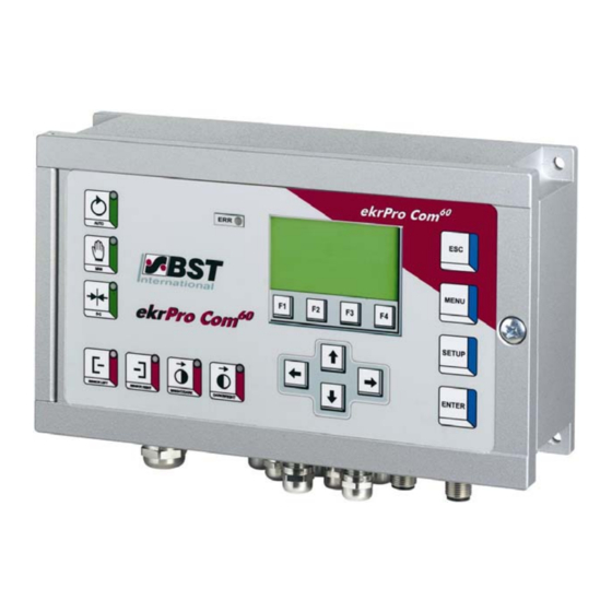
- Page 30 Controls B 2 Display and operating controls B 2.1 Control panel Graphics display A contrast-rich LCD display with LED background illumination. Display has 6 lines, each of 28 characters. The graphics display is used for displaying the operating hours, parameters and the set-up menus. Keypad The controller can be configured for operation using this keypad.
- Page 31 Controls Function Menu navigation: Jump back by one level In editing box: Cancels the last entry Select controller settings or controller gain for change the settings Saves the settings at the end of the set-up functions Activates special functions (e.g. oscillation) (not used at the present moment) Menu selection B 2.2 Navigating within the system...
- Page 32 Controls B 2.2.1 Function keys (F-keys) The F-keys functions are assigned in different dialog windows. The associated abbreviated names are displayed at the bottom edge of the screen. Press the relevant F-key several times to select the required numerical value. The time interval in between pressing the button twice must never exceed 0.5 seconds.
- Page 33 Controls Entries in the editing box The parameter values are entered directly in the editing box. This can also be realised using the F-keys. 1. Open the required sub-menu and then press the ENTER key to activate the editing box. 2.
- Page 34 Controls Entering negative numbers Use the horizontal arrow keys to mark the initial position for the setting. Now use the vertical arrow keys so that the minus sign is entered or removed. After this, enter the digit sequence as described above. B 2.2.2 Arrow keys Various entries can be made and options can be selected from the menu mode dialog windows.
- Page 35 Controls Checkbox Use the vertical arrow keys Arrow keys option using the checkbox control element. Example: (de)activate speed control = Option active active = Option inactive Read-only Checkbox Read-only checkboxes only have a display function. These give the operator reports about the current status of the components (e.g.
- Page 36 ...) using the system parameters in the individual setup menus. The required parameters have already been entered if the control system is an integral part of a projected BST system. You do not have to reset anything with regard to this.
- Page 37 Commissioning B 3.2 Electrical connections The system must be wired according to the accompanying connection diagram or plugged into the appropriate cable sockets. Standard wiring sleeves with collars (DIN 46228/Part 4) must be used with all cable connections up to 0.75 mm². Wiring sleeves must not be used with cables from 0.75 mm²...
- Page 38 Commissioning B 3.3 Commissioning with a CAN Bus B 3.3.1 Checking the unit address and setting up if necessary If the ekrPro Com controller is operated via a CAN bus, then the setting of the CAN device address must be checked. The CAN device address setting up is carried out via the S1 BCD switch on the processor board: BCD switch S1...
- Page 39 Commissioning (if fitted) :ekrPro Key60: ekrPro Key There are several plugs on the rear side of the ekrPro Key The BCD switch S1 for setting the address (node number) is behind these plugs. Procedure: 1. Switch-off the power to the controller. S1 BCD switch 2.
- Page 40 Commissioning B 3.3.2 Terminator activation The terminator must be activated on each of the physical first and last CAN bus participants. The possible settings are described below. B 3.3.2.1 ekrPro Com In the ekrPro Com , the activation is carried out using switch S3 on the processor circuit board.
- Page 41 Commissioning (if fitted) B 3.3.2.3 BST ProLogic In the BST ProLogic activation takes place using the DIP switch segment 1 (S1 = ON) for the CAN 1. CAN 2 (if fitted) B 3.3.2.4 FVGPro Module In the FVGPro Module activation is carried out via switch S3 on the processor circuit board.
- Page 42 Make sure these new passwords are only known to the authorized personnel! BST International GmbH is not liable for damage arising from the incorrect use of the password(s). An automatic logout time can be set for all user levels (timeout time).
- Page 43 Select the desired user level with the up and down arrow Current Admin. user level BST Support keys. Confirm the selection by pressing ENTER. Enter user level & password 3. Use the right and left arrow keys to select the Password User level Mainten.
- Page 44 Commissioning B 3.5 Commissioning standard system To simplify commissioning, the commissioning staff can select his own system from a list of the most common standard systems listed under the menu Sel. Std. System. Following the selection, all of the basic settings are automatically entered in the setup menu and the system is switched to the operating mode MAN.
- Page 45 Attention! If the mounting position of the selected sensor differs from the BST setting (see chapter A 1.4) or if the sensor outputs an inverted signal (e.g. another manufacturer’s sensor is being used), then the checkbox Inv. must be checked.
- Page 46 Commissioning B 3.5.3 Setting the actuator guiding direction For standard systems, the EMS17 is registered as the actuator. The direction has to be set for it. 1. Select the sub-directory Direction from the menu Actuator. Confirm the selection by pressing ENTER. If necessary, the actuator guiding direction for manual mode can be reversed by activating the checkbox Mot.
- Page 47 Commissioning 5. Use the F3 key to traverse the actuator until it reaches the required right limit switch position. 6. Confirm this position by pressing the F4 key. 7. Reactivate both limit switches. Select (x) checkbox active to do this. The description is given in section 2.
- Page 48 Commissioning B 3.5.6 Carry out material setup Automatic adjustment of the controller to match the characteristics of the material to be scanned is carried out during material set-up (e.g. different material transparency at the optical sensors or different sound absorption in the case of ultrasonic sensors). The material set-up is the same for all three sensors.
- Page 49 Commissioning B 3.5.6.1 Automatic material set-up 1. Press the F1-key. 2. Completely cover the sensor’s scanning window with the material to be scanned for approx. 2 seconds. 3. Completely remove the material from the sensor scanning window (no material over the sensor). 4.
- Page 50 Commissioning B 3.5.7 FVG - Sensor positioning device The stepping motor output stages are not protected against short circuits. You must check, without fail, using a suitable test unit (ohmmeter) that no short circuits or cross-connections between the two windings exist before starting the commissioning.
- Page 51 Commissioning - Range – Traversing range limits • at the first setting after switching on: min = 0.0 max = 5000.0 - Feed – Feed for stepping motor / gearing combination This setting is treated as the feed per motor revolution for the stepping motor / gearing combination.
- Page 52 Commissioning Slide 2 - Homing Direction – retraction direction and end switch assignment • at the first setting after switching on: reversed - Offset - positional offset to FVG position • at the first setting after switching on: Offset = 2000 Inverted = yes - Range –...
- Page 53 Commissioning - Repositioning – repositioning of the material after certain events The current position of the material web is saved once an event takes place (e.g. web tear). Once the event has been rectified, the material is repositioned to this position. This functionality is only effective once pre-positioning has been activated.
- Page 54 Commissioning B 3.5.8 Add. Functions – Special functions Useful additional functions can be realised using the ekrPro Com These functions can be accessed quickly under this menu point. These functions deal with the Tear Off Detection and Oscillation. B 3.5.8.1 Tear-Off Det.
- Page 55 Commissioning Criteria for detecting a tear: To detect a tear, at least one of the two following criteria must be fulfilled: 1. Exceeding / undershooting of the preset threshold value If the sensor signal exceeds or falls below the set threshold value (threshold), then this is recognised as a tear.
- Page 56 Commissioning Example calculation: At a maximum web speed v = 300 m/min and a light spot diameter d = 8 mm the resultant minimum mark length L equals: 300 m/min 8 mm 0,004 s 60 s/min 1000 mm/m = 0,068 m = 68 mm 2.
- Page 57 Commissioning Parameter settings Setting of the parameters for the function tear-off detection is made separately for each guiding mode. If necessary, a different sensor can be allocated as the tear-off detection sensor for each guiding mode. It is also possible to allocate two different guiding modes with different parameters to a single sensor.
- Page 58 Commissioning Calculation of the maximum allowable rate of change of the sensor signal (parameter sign. chg. limit) The maximum permissible rate of change sig. chg. limit of the sensor signal, depends of the minimum web speed v diameter d, of the contrast sensor light spot and can be calculated using the following formula.
- Page 59 Commissioning • SC: Activation in operating mode SC using the servo-center component. • FVG Auto: Oscillation with connected FVG An FVG oscillation with sine-shaped web repositioning. 3. Press the ESC button to exit the window. Osc. Params. – Set oscillation parameters The oscillation parameters, i.e.
- Page 60 Commissioning Osc. Params Add-on – Additional functions for oscillation (can only be used for the sensor oscillation) Additional specifications can be set for the sequence of the oscillation in this sub-menu. 1. Select the sub-menu Osc. Params Add-on and confirm with ENTER. 2.
- Page 61 Commissioning B 3.7 Setup menu The system parameters are saved in the Setup menu and they can also be modified from here. The menu structure is shown in Appendix D1. B 3.7.1 Change User Selection of user level- User administration in the ekrPro Com differentiates between four different user levels with different user rights.
- Page 62 Commissioning B 3.7.5 General Setup - System parameters All of the parameters that have to be set up once when aligning the system are contained in the General set-up. The following procedures are provided for the different operating modes. However, the default values should be loaded before the special parameters are set up.
- Page 63 Commissioning B 3.7.5.2 Actuator – Actuator settings B 3.7.5.2.1 Type (EMS&Hydr.) – Actuator selection The relevant servo center component must be entered before starting the commissioning (see chapter B 3.7.5.2.4 ”servo-center component settings“). Any remote control which may possibly be running, must be deactivated! The preset actuator is the EMS 17.
- Page 64 Commissioning B 3.7.5.2.2 Hydraulics Add-on – Hydraulic settings If a hydraulic actuator is used, then additional hydraulic settings must be made in the menu Hydraulics Add On. 1. Select Actuator in General Setup and then select the Hydraulics Add-on sub-directory afterwards. Confirm the respective selection by pressing ENTER.
- Page 65 Commissioning Digital blocking output (oil blocking) If a hydraulic actuator is used, then a blocking valve can be connected to terminal 67 (X15), in order to interrupt the oil flow. Oil blocking is only active with a hydraulic actuator and when one of the following conditions is fulfilled: •...
- Page 66 Commissioning B 3.7.5.2.4 SC Transducer - Servo-center component settings Type & Dir. – Selecting the servo-center component 1. Select the sub-directory SC-Transducer from the Actuator menu and then select Type & Dir.. Confirm the respective selection by pressing ENTER. 2. Use the horizontal left or right arrow keys in the newly not connected opened window to select the servo-center component selection window and confirm it by pressing ENTER.
- Page 67 Commissioning Pos. Limit – Setting the actuator path limits (software limit switches) This sub-directory is only be used if an actuator with position feedback (for example, EMS 17) is connected to the system. This enables you to limit the actuator paths. 1.
- Page 68 Commissioning SC W & XP – Setting the centre position and the gain for the SC operating mode This sub-directory is only be used if an actuator with position feedback (for example EMS 17) is connected to the system. In this case the centre position setting option and the gain have to be set up for the SC operating mode.
- Page 69 Commissioning B 3.7.5.2.5 Man Pos Control – Activation of the Position Controller The position controller for ”manual” mode can be activated for actuators with position feedback (e.g. EMS 17). With the position controller activated, the actuator keeps the actual position when in manual mode, independently of any external forces acting on the drive (self-locking).
- Page 70 Attention! If the mounting position of the selected sensor differs from the BST setting (see chapter A 1.4) or if the sensor outputs an inverted signal (e.g. another manufacturer’s sensor is being used), then the checkbox Inv. must be checked.
- Page 71 Commissioning Attention! If a reflection sensor is being used as Sensor 3 then only this sensor must be selected and entered from the option list. You do not have to run a master set-up. B 3.7.5.3.2 EFE Remote Adj. – Commissioning of remote electronic fine adjustment (EFE) A remote electronic fine adjustment unit is not identified automatically by the controller.
- Page 72 Commissioning B 3.7.5.4 Control Loop - Control loop settings The parameters for the control circuit are set up in this sub-menu. B 3.7.5.4.1 Gain & Offset – Amplification & setpoint values 1. Select Control Loop in General Set-up and confirm by pressing ENTER afterwards.
- Page 73 Commissioning B 3.7.5.4.3 Speed Control – Speed regulation When speed control is activated, speed variations, which can be caused by varying loading of the actuator, are automatically compensated. This activation of this function is a default setting. It must be deactivated if a tacho-generator is being used. 1.
- Page 74 Commissioning B 3.7.5.5 FVG – Sensor positioning device The control unit integrated in the controller for running the sensor positioning device can be parameterised in this sub-menu. A stepping motor drives the sensor adjustment unit. The stepping motor output stages are not protected against short circuits.
- Page 75 Commissioning Once the selection has been made, specific settings must be carried out for the FVG eco, FVG 1MK Op. and FVG 2MK Op. modes. B 3.7.5.5.2 FVG eco The FVG eco mode allows the sensors/FVG slides belonging to the FVG connected to be moved using the controller arrow keys.
- Page 76 Commissioning The outside FVG1 limit switch has been determined as the reference point for the FVG slide (offset = 0.0 mm) Offset Offset 2 (FVG) FVG 1 FVG 2 Web running direction Offset 1 – position offset to FVG1 slide position You can use the position offset to, for example, set the home position (= 0.0 mm) to a fixed point, e.g.
- Page 77 Commissioning Range – Traversing range limits The traversing range limits are entered in the menu Range. They are the basis for displaying the traversing movement in the operating status screen. 1. Select Range from the sub-directory and then press ENTER to open the inputting menu.
- Page 78 Commissioning B 3.7.5.5.4 FVG Pro The FVG Pro submenu is used when the FVG 2MK Op. mode has been selected (usually when using an FVG 2MK). In this case, each FVG needs to be adjusted separately. The terms used here FVG 1 (Slide 1) and FVG 2 (Slide 2) relate to the arrangements in accordance with Point A 1.4.5.
- Page 79 Commissioning Offset – positional offset to position of first FVG slide You can create a reference system with an absolute reference point using the positional offset. This reference point can, for example, be the machine wall or another obvious point on the machine. It is also possible to use an outer position or the centre of the FVG.
- Page 80 Commissioning The standard operating display now shows the position of the centre of the measurement window belonging to the appropriate sensor based on the reference point. Range – Traversing range limits for first FVG slide The traversing range limits are entered in the menu Range. They are the basis for displaying the traversing movement in the operating status screen.
- Page 81 Commissioning Feed – Feed for stepping motor/gearing combination This setting is treated as the feed per motor revolution for the stepping motor / gearing combination. The manufacturer has entered this default setting and you are only permitted to modify it (if necessary) after having obtained the manufacturer’s agreement.
- Page 82 Commissioning 1. Select Norming Mode from the sub-directory and then press ENTER to open the selection menu. 2. The following norming modes are available in the selection menu: • Bright: Only a bright setting standardisation will be carried out. This standardisation mode is normally used Select a norming mode for the infrared sensor IR 2002 with Bright...
- Page 83 Commissioning 25% covering Start of sensor tracking 50% covering End position 75% covering Start of sensor tracking The approach of the sensor towards the • Lvl. Outer: material web generally occurs from the outside. The FVG operating mode can be carried out in the MAN mode, in the Automatic mode as well as the SC mode.
- Page 84 Commissioning B 3.7.5.5.9 - Velocities – adjustment of positioning speeds This function can be used to adapt the positioning speeds for various actions. 1. Select Velocities from the sub-menu and then press ENTER. 2. The standard values are already entered in the settings menu.
- Page 85 Commissioning B 3.7.5.5.10 - Special – Special settings for moving the FVG slides during edge searching 1. Select Special from the sub-directory and then press ENTER to open the inputting menu. 2. Standard values have already been entered. These can be accepted as is or adapted to the application. 3.
- Page 86 Commissioning B 3.7.5.6 Width Measure - Web width measurement The parameters required when using a width-measuring unit are set up in this sub-menu. B 3.7.5.6.1 Ref. Width – Width of the calibration sheet A piece of material with a known width must be used once as a reference for adjusting the web width measurement.
- Page 87 Commissioning B 3.7.5.6.2 Limits – Set width, error and warning limits The set value for the web width (Nominal Width) is entered in this window. The lower and upper error limits (E+, E-) and the lower and upper warning limits (W+, W-) are also set up here. The measuring unit is mm.
- Page 88 Commissioning 1. Select Limits in the selection window and press the ENTER key. This will open up the input window. 2. Enter the nominal value for the material width in the edit field Nominal Width. 3. Enter selected values for the error and warning limits in the corresponding edit fields.
- Page 89 Commissioning B 3.7.5.7 Edge Sources - Assignment of the sensors to the scanning modes The ekrPro Com controller allows the free assignment of the connected sensors to different scanning modes. Therefore each scanning mode can have the input signal of any sensor allocated to it.
- Page 90 Commissioning 9. The input value supplied by the selected sensor can be shown in this window as either an absolute or normalized (percentage) value. To activate normalized display, select checkbox norm.. 10. If necessary, the checkbox inv. is used to invert the input signal delivered by the sensor.
- Page 91 Commissioning B 3.7.5.8 Add. Functions – Special function Explanations for the requirements and function of both special functions can be obtained under point 3.5.8. The parameter settings are carried out as follows: B 3.7.5.8.1 Tear Off Det. – Tear Off Detection Setting of the parameters for the function Tear-off detection is made separately for each guiding mode.
- Page 92 Commissioning 4. If necessary, set parameters for further guiding modes (see points 2 and 3). 5. Press the ESC button to exit the window. B 3.7.5.8.2 Oscillation This special function enables the position of the web of material to be displaced within the sensor´s visual range using adjustable amplitude (size of the lateral displacement) and frequencies (displacement speed).
- Page 93 Commissioning Osc. Params. – Set oscillation parameters The oscillation parameters, i.e. amplitude and frequency, are set in this submenu. 1. The Osc. Params submenu Select Sensor 1 and confirm by pressing ENTER. 2. The parameters have the following meanings: ► Amplit. Auto [%]: Amplitude of the oscillation in operating mode Automatic.
- Page 94 Commissioning B 3.7.5.9 Dig. IO Config. - Configuration of the digital inputs and outputs B 3.7.5.9.1 Configure – selection of digital input table and activation of inputs/outputs You can select from two tables in this dialog window. Both contain various assignments for the digital inputs (see Point B 3.7.5.9.3).
- Page 95 Commissioning Example 1: The function Tear-off detection is to be assigned to the digital inputs (lines 29 and 30). In so doing, the standard bit-pattern for lines 29 and 30 must not be changed. 1. Select Dig. IO in General Setup and then select the Inputs sub-directory afterwards.
- Page 96 Commissioning Example 2: The function Tear-off detection is to be assigned to the digital inputs (lines 21 and 22). The following section of the truth table shows that lines 21 and 22 belong to a bit-block with a total of 8 lines (lines 21 to 28). Factory allocation of functions with the corresponding standard bit-patterns Terminal...
- Page 97 Commissioning Step 1: Cancel the factory allocations of functions. As the function tear-off detection requires only lines 21 and 22 of the bit block, the factory-side allocation of functions to the remaining lines of the block (lines 23 to 28) must be cancelled. Accordingly the function Do Nothing is allocated to lines 23 to 28 from the option list.
- Page 98 Commissioning B 3.7.5.9.3 Truth table Default values for digital input allocation: Dig. InTable 1 Terminal Line Significance set Auto (automatic mode) set MAN (manual mode) set SC (servo center position) opmode clear (defined zero state operating mode) set Edge1 (edge 1) set Edge2 (edge 2) set Center1&2...
- Page 99 Commissioning Terminal Line Significance Reset Lim.Sw. 2 (reset stop switch 2) Reset Lim.Sw. 2 (reset stop switch 2) Set Overtemp. (over-temperature) Reset Overtemp. (reset over-temperature) Keyb.Lock ON (keyboard interlock on) Keyb.Lock OFF (keyboard interlock off) 31 - Do Nothing (reserved) Alternative digital input allocation: see Dig.
- Page 100 Commissioning Terminal Line Signification Set limit switch 1 Reset Lim.Sw. 1 Reset Lim.Sw. 1 Set Lim.Sw. 2 Reset Lim.Sw. 2 Reset Lim.Sw. 2 Set Overtemp. Reset Overtemp. Ext. Unlock Ext. lock 30 - Do Nothing (reserved) 0 = 0 V signal 1 = 24 V signal X = not relevant Controller interlock...
- Page 101 Commissioning B 3.7.5.9.4 Outputs – Digital outputs This sub-menu allows various messages to be assigned to the digital outputs of the control unit (terminal 64 – 67). The meaning of the individual messages can be taken from the table on the following page. 1.
- Page 102 Commissioning Signification of the messages Report Significance no Errors OK message output Width err. min. Web width measurement: Web width has fallen below the lower error limit. Width warn min. Web width measurement: Web width has fallen below the lower warning limit. Width warn max.
- Page 103 Commissioning B 3.7.5.10 Special - Special device settings Passwords can be changed, the firmware can be restarted and the default delivery state can be reset from the Special sub-menu. B 3.6.4.10.1 Change Password This window is used to set the password for current active user level and the timeout time for an automatic logout.
- Page 104 Commissioning B 3.6.4.10.2 Dev. Config. – General unit settings The general ekrPro Com unit settings are entered in the Dev. Config. sub-menu. 1. Select Special in General Set-up and confirm by pressing ENTER afterwards. 2. Select Dev. Config. in the following window. 3.
- Page 105 Commissioning B 3.7.5.10.3 Reset – Reset of the firmware Resetting the firmware might be necessary, for example, if the controller: • The display settings are wrong • The LEDs in the buttons do not illuminate • The error LED cannot be extinguished. A defined state is set up when the unit is reset.
- Page 106 Commissioning B 3.7.6 Opt. Logic - Optional logic It is possible to integrate an optional logic module in the for customer specific applications. ekrPro Com In this case there will be a separate branch available in the set-up menu. The separate windows can still be called up even if an optional logic module has not been integrated, but you cannot make any entries.
- Page 107 Commissioning B 3.7.8 Remote Device – Unit remote control via CAN bus Devices in the controller family (ekrPro Com , ekrPro Key ) can be interconnected via a CAN-Bus to form a networked system. The function Unit remote control allows to operate the controllers available in the system from different sources (e.g.
- Page 108 Automatic ............14 CAN-Bus Manual .............. 14 Checking and setting up the unit address ..3 Sensor compensation ........26 ekrPro Com60 ..........3 Save settings ........... 25 ekrPro Key60..........4 FVGPro Module........... 4 Setup-Menu ............. 26 Commissioning ........... 3 Change User - Selection of user level ....
- Page 109 Terminal diagrams / Service displays Terminal assignments and service displays B 4.1 Board overview ekrPro Com web guide controller EDV-No.: MD.191.01.05/1.6.x Appendix B 4 with analog sensors Date: 23.11.2007 Page: 1/9...
- Page 110 Terminal diagrams / Service displays B 4.2 Terminal diagrams B 4.2.1 Overview Terminal Function Remarks strip Analog sensor 1 Analog sensor 2 Analog sensor 3 SC encoder / Namur Analog sensor 4 Power supply 24V DC Input DC motor (controller) Enable and reference switch (FVG) Stepping motor (FVG) Digital inputs...
- Page 111 Terminal diagrams / Service displays B 4.2.2 Terminal strip X1; Sensor 1: Plug Terminal Function Remarks Internal connection to terminal 8 IR pulse + 5 V/ Synchronisation for US sensor IR pulse GND + 12 V Output + 12 V - 12 V Output –...
- Page 112 Terminal diagrams / Service displays B 4.2.5 Terminal strip X4; Sensor 3 / EFE / OZ3: Terminal Function Remarks +5V / 1A GND (+5V) +12V Output ±12V -12V Output -12V Analog input 7 Sensor 3 Analog input 1 EFE1 / OZ3 B 4.2.6 Terminal strip X6;...
- Page 113 Terminal diagrams / Service displays B 4.2.9 Terminal strip X10; Enable and reference switch (FVG): Terminal Function Remarks GND for enable actuator +24V +24V output for enable actuator Enable actuator Enable actuator input. Link to terminal 52 if not used GND for enable FVG +24V +24V output for enable FVG...
- Page 114 Terminal diagrams / Service displays B 4.2.11 Terminal strip X14; Digital inputs: Terminal Function Remarks GND for inputs 0 - 11 Input 0 Input 1 Input 2 Input 3 Input 4 See truth table Input 5 (chapter B 3.7.5.9.3) Input 6 Input 7 Input 8 Input 9...
- Page 115 Terminal diagrams / Service displays B 4.2.13 Terminal strip X16; Analog output and tacho input: Terminal Signal Remarks GND for analog output Output ±10V Analog output for external motor output stage. Not for direct connection of hydraulic components SV1 …, HR 024, HR 040, EH-St 9/3.
- Page 116 Terminal diagrams / Service displays B 4.2.15 CAN connection assignments: The controller is connected to the CAN bus via a 5-pin M12 micro style connector. The maximum individual contact nominal current is 4A. Contact assignments in the plug connector: View on the screw side Socket Plug (female)
- Page 117 Terminal diagrams / Service displays B 4.3 Service indicator displays B 4.3.1 LEDs “Power supply“ Name Status Significance +12V Internal +12V not present Internal +12V present -12V Internal -12V not present Internal -12V present Internal +5V not present Internal +5V present +5PV Internal +5V not present (lamp voltage)
- Page 118 ekrPro Com with analog sensors Section C Operation Controls Operation Error messages Maintenance ekrPro Com web guide controller EDV No.: MD.191.01.05/1.6.x with analog sensors Date: 23.11.2007...
- Page 119 Contents Section C Operation Table of contents Display and operating controls C1-1 C 1.1 Control panel C1-1 C 1.2 Navigating within the system C1-2 C 1.2.1 Function keys (F-keys) C1-2 C 1.2.2 Arrow keys C1-4 C 1.2.3 Buttons C1-6 Operation C2-1 C 2.1 General information...
- Page 120 Controls C 1 Display and operating controls C 1.1 Control panel Graphics display A contrast-rich LCD display with LED background illumination. Display has 6 lines, each of 28 characters. The graphics display is used for displaying the operating hours, parameters and the set-up menus. Keypad The controller can be configured for operation using this keypad.
- Page 121 Controls Function Menu navigation: Jump back by one level In editing box: Cancels the last entry Select controller settings or controller gain for change the settings Saves the settings at the end of the set-up functions Activates special functions (e.g. oscillation) (not used at the present moment) Menu selection C 1.2 Navigating within the system...
- Page 122 Controls Shortcut functions The function keys are assigned numbers in the equipment menu. Therefore a menu option can be selected by using the arrow keys to navigate to the required menu sub-option or it can be selected directly by using the shortcut number instead. For example: Selecting the actuator The associated menu sub-option is 611 (see navigation overview as well).
- Page 123 Controls Entries in the editing box The parameter values are entered directly in the editing box. This can also be realised using the F-keys. 1. Open the required sub-menu and then press the ENTER key to activate the editing box. 2.
- Page 124 Controls Option lists An entry from a default list can be selected from an option list. This is realised by pressing the ENTER button to open the selected option list. Example: Select an actuator type Select an actuator type EMS 10 EMS 17 EMS 16 EMS 17...
- Page 125 Controls Editing box The arrow keys can also be used to enter a value in the editing box in addition to using the F-keys. Width Measure Offset current width: Selected digit Opened 78.5 enter ref.width editing box Use the horizontal arrow keys to position the cursor on the number to be modified.
- Page 126 Operation C 2 Operation C 2.1 General information C 2.1.1 Graphics display The various operating statuses are displayed by the graphics display. Use the vertical arrow keys to change between the different displays in normal control mode. The number of displays varies between one and four, depending on whether a sensor adjustment unit and/or sensor 3 is interconnected or not.
- Page 127 Operation Screen with active web width measurement (only with connected sensor positioning device) Graphic display of current web width Graphic representation of: warning limit error limit Entry field for intended web width Accept current web width as intended web width Actual system condition display Numeric display of current web width Switching between...
- Page 128 Operation Display of pre-positioning Display when using FVGPro (normally FVG 2MK) Guiding mode; E1 = Edge 1, C1&2 = centre between edge 1 and 2, E2 = Edge 2 Position setpoint for appropriate guiding mode. The selected entry will be displayed "inversely". Current position value for sensor(s) Accept current position value as new setpoint for active guiding mode.
- Page 129 Operation Display of the CAN bus state Display of CAN node number Display of CANopen control unit operating status CANopen network synchronisation operating status screen No Sync = Control unit not receiving synchronisation impulse No Sync = Control unit receiving synchronisation impulse Checking functions for device remote control If you press the ENTER key on the control unit, all LEDs on the keypad belonging to the remote-controlled device...
- Page 130 Operation C 2.2 Changing the settings during operation Use the membrane-keys to set up the operating functions and the scanning modes as well as the settings and to optimise the controller gain. C 2.2.1 Operating functions Proceed as follows to set up the required operating functions: Automatic mode Press the “AUTO“...
- Page 131 Operation C 2.2.2 Scan start The required scanning mode is set up as follows: Web edge guiding: left web edge* Press ”SENSOR LEFT” key. Web edge guiding: right web edge* Press ”SENSOR RIGHT” key. * in the material running direction! Web center guiding Press the “SENSOR LEFT“...
- Page 132 Operation C 2.2.3 Gain adjustment The controller gain can be set up directly in the operating status display or in the set-up menu. The operating status display settings are described in the following. The system must be in “AUTO” mode. Press the SET-UP button and the parameters displayed in the line at the bottom of the screen will change from the displayed setpoint (W) to the gain setting (XP).
- Page 133 Operation C 2.3 Sensor positioning device C 2.3.1 Using the FVG function, general If an FVG is being used in combination with Sensor 3, the FVG automatically retracts if the controller is switched to Sensor 3. The requirement for this is, however, that the element which is being used to regulate (normally a line) lies within the visual range of Sensor 3.
- Page 134 Operation Allocation of the change-over options to the operating modes available options for the available options for the digital inputs FVG mode keyboard arrow keys terminal 80 = Low terminal 80 = High Operating mode AUTO connected switch over via SETUP button FVG eco switch over via SETUP button switch over via SETUP button...
- Page 135 Operation C 2.4 Material set-up Automatic adjustment of the controller to match the characteristics of the material to be scanned is carried out during material set-up (e.g. different material transparency at the optical sensors or different sound absorption in the case of ultrasonic sensors). The material set-up is the same for all three sensors.
- Page 136 Operation C 2.4.1 Automatic material set-up 1. Press the F1-key. 2. Completely cover the sensor’s scanning window with the material to be scanned for approx. 2 seconds. 3. Completely remove the material from the sensor scanning window (no material over the sensor). 4.
- Page 137 Operation C 2.4.3 Special procedure if an analog reflection sensor is connected as Sensor 3 1. Select required scanning mode (BRIGHT/DARK or DARK/BRIGHT). Automatic material set-up: • Press the F1-key • Position the sensor’s light spot on the bright contrast area for approx.
- Page 138 Operation C 2.4.4 Manual material set-up for sensors T 62 D 1 and TW 54 C5 C 2.4.4.1 Settings for the T 62 D1 Prior to carrying out of the material setup, the zero point should be reset for sensor T62 D1. This is different dependent on whether the sensor is being used for line sampling or for contrast sampling.
- Page 139 Operation C 2.4.4.2 Material set-up For critical contrast transitions, this function enables optimum adjustment of the reflection sensor TW 54 C5 or the line sensor T 62 D 1 to the properties of the material to be scanned. In addition to the normal material setup, the offset value and gain for sensor 3 can also be set here.
- Page 140 Operation C 2.5 Tear-off detection “Tear-off detection” enables, dependent on the selected sensing type (edge / contrast guiding) the following functions: 1. With web edge guiding: Detection of torn-off sections on the web edge using edge sensors IR2001/2005, US2007, … This function is activated during web edge guiding, if during operation of the web guiding system errors arise from the web edge that is being scanned.
- Page 141 Operation Activate tear-off detection 1. Press the F2-key. The function “Tear-off detection” is activated. If an outward or inward tear is detected, this is indicated in the display by an exclamation mark. As soon as the guiding system is blocked, a lock appears in the actuator symbol.
- Page 142 Operation C 2.7 Pre-positioning You can use this function to carry out material web pre-positioning to a position determined by a user. Both the guiding mode on which the pre-positioning is to be used and the target web position itself can be set. Activate pre-positioning (FVGPro) Select the required guiding mode in the "set“...
- Page 143 Operation C 2.8 Pre-positioning to machine centreline (only with FVG 2MK) This function is used to pre-position the material to the machine centreline. The predefined machine centreline is calculated from the offset value settings which were defined during the start-up procedure (see Point B 3.7.5.5.4 and example below).
- Page 144 Operation C 2.9 Unit remote control via CAN bus Devices in the controller family (ekrPro Com , ekrPro Key ) can be interconnected via a CAN-Bus to form a networked system. The function "Unit Remote Control" enables control of the control units present in the system to be undertaken from different origins (e.g.
- Page 145 Error reports C 3 Error reports Errors are indicated by the error LED illuminating. You can chose to display them or suppress them. Furthermore, the display duration of a reported error can be varied. These settings are made in the menu General Setup >...
- Page 146 Error reports Report Possible cause Solution - Guiding device has moved Activate into the opposite into a stop position or is direction. MOTOR OVERCURRENT blocking the motorised guide. Error report will be deleted automatically. - Actuator short circuit Find the cause of the short MOTOR SHORT CIRCUIT The actuator controller was circuit...
- Page 147 Error reports Fault Possible cause Solution An error has occurred during Check sensor. sensor normalisation. If necessary clean sensor. NORMING ERROR No guidance is possible. Insert material and repeat sensor normalisation. During edge detection the Insert material and repeat edge FVG slide has reached the detection.
- Page 148 Error reports Fault Possible cause Solution The controller does not respond A remote controller has been Check terminal 85. Remove the to any operation. connected to the control “1“ signal (24V DC) if present. system. It has blocked the controller buttons.
- Page 149 Maintenance C 4 Maintenance C 4.1 ekrPro Com controller The controller is maintenance-free. Cleaning should be carried out using a dry, clean and soft cloth. A commercial liquid cleaner may be used if the casing is very dirty. Adhere to protection class IP 54! Beware! The controller has to be switched off! C 4.2 Sensors...
- Page 150 ekrPro Com with analog sensors Section D Appendix To open the set-up menu Default settings Commissioning example Connection diagram / Plug assignments System overview Flange board connection ekrPro Com web guide controller EDV-No.: MD.191.01.05/1.6.x with analog sensors Date: 23.11.2007...
- Page 151 Add. Functions Tear Off Det. CanOPEN Osc. Mode Osc. Params Dig. IO Config. Configure Remote Device Inputs Outputs Special Change Pwd. Dev. Config. Reset Appendix D 1 System overview Watchdog Test For BST support only! EDV-No.: MD.191.01.05/1.6.x Test Issue: 23.11.2007...
- Page 152 Default settings Appendix D 2 Default settings The default settings have been set up in the controller in the factory. The following settings are set up again after a reset has been carried out: Parameter Level 3 Default Value Menu Parameter Level 1 Parameter Level 2 Change User User Level...
- Page 153 Default settings Menu Parameter Level 1 Parameter Level 2 Parameter Level 3 Default Value Connection Op. Mode not connected Int. FVG FVG sensor adjustment Homing Dir. Homing dir. inv. not reversed unit Ref. switch inv. not reversed Offset 1 Offset [mm] Only for internal Inverted FVG!
- Page 154 Default settings Menu Parameter Level 1 Parameter Level 2 Parameter Level 3 Default Value Width Measure Ref. Width [Press “set ref”!] Limits Nominal width 80.0 Error -5.0 limits +5.0 Warning -2.0 limits +2.0 Edge Sources Edge 1 Device This device Edge Sensor 1 Inverted...
- Page 155 Default settings Menu Parameter Level 1 Parameter Level 2 Parameter Level 3 Default Value Add. Functions Tear Off Det. Edge 1 Sensor none Threshold [%] 80/20 Sign. chg. limit [%/4ms] Delay time [ms] Hold time [ms] Edge 2 Sensor none Threshold [%] 80/20 Sign.
- Page 156 Default settings Menu Parameter Level 1 Parameter Level 2 Parameter Level 3 Default Value Opt. Logic Params 1 Params 2 Fieldbus Status Bus type unknown Module status Data exchange not running Last interrupt Profibus Address Swap Bytes Swap Words DeviceNet Address Baudrate 500 kbps...
- Page 157 Default settings Menu Parameter Level 1 Parameter Level 2 Parameter Level 3 Default Value Outputs Clamp 64 No errors Low act. Clamp 65 W. warn nor err. min. Low act. active Clamp 66 W. warn nor err. max. Low act. active Clamp 67 Hydr lock...
- Page 158 Commissioning example Appendix D 3 Commissioning example Set-up menu navigation, menu sequences and general procedures are described in the ”Commissioning“ section. The details in this section refer to the special components with information about the menus that have to be used or setting up windows.
- Page 159 Commissioning example D 3.2 Start-up an actuator with OMG 4 / 7 / 8 1. Wire in the motor and servo-center component as shown in the circuit diagram. 2. Go to General Setup > Actuator > Type (EMS&Hydr.) and select the actuator.
- Page 160 Commissioning example D 3.4 Initial startup with sensor positioning device FVGPro 2/MK 1. Carry out electrical connections as specified in the circuit diagram. 2. Reset the parameters to the works settings. To do this open the “Sel.Std.System” menu and select F1 („Def.“). The ekrPro Com carries out a restart.
- Page 161 Commissioning example 5. Check sensors connected and readjust it if necessary. Check to ensure that the percentage display value increases the more the sensor is covered. If not, check whether inverting is set. After this, the Master setup for this sensor has to be carried out. Press the F1 („auto“) button.
- Page 162 System overview BST Bus System ekrPro Com ekrPro Key EFE1 Actuator without Electronic remote position feedback fine adjustment FVG 1K.../FVG 1MK... Analog sensors Sensor positioning device with and Servo-center without material width measurement Actuator with component position feedback FVG 2K.../FVG 2MK...
- Page 163 Flange connection plate Appendix D 6 Connecting plate ekrPro Com ; XT version Actuator (motorised/hydraulic) Line / contrast sensor Sensor positioning device Analog sensors CAN Bus connection X100 External 24 VDC X101 Outputs 24 VDC Servo-center power supply component ekrPro Com web guide controller EDV-No.: MD.191.01.05/1.6.x Appendix: D6...
Need help?
Do you have a question about the ekrPro Com60 and is the answer not in the manual?
Questions and answers