Table of Contents
Advertisement
Quick Links
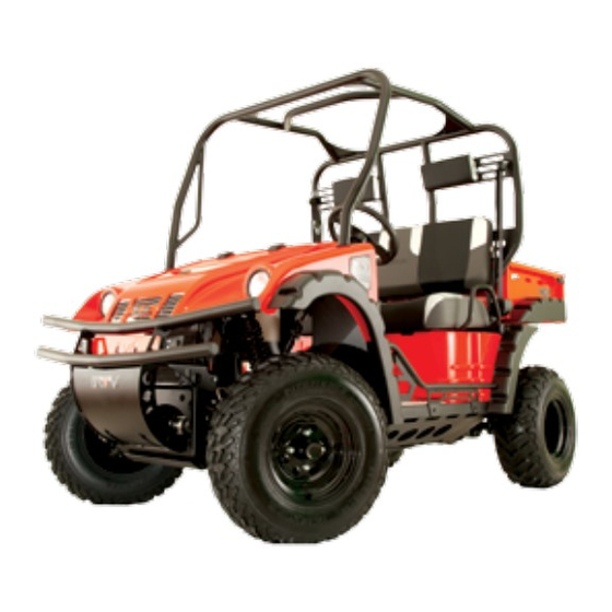
Multi-Terrain Vehicle
(MTV)
Service Manual
All information contained within this publication is based on the
latest product information at the time of publication. Due to
constant improvements in the design and quality of production
components, some minor discrep ancies may result between the
actual vehicle and the information presented in this publi cation.
Model 1500
(Gas Powered)
Advertisement
Chapters
Table of Contents
Troubleshooting

Related Manuals for Bad Boy 1500


Summary of Contents for Bad Boy 1500
- Page 1 Due to constant improvements in the design and quality of production components, some minor discrep ancies may result between the actual vehicle and the information presented in this publi cation. Model 1500 (Gas Powered)
- Page 2 This service manual contains the technical data of each component inspection and repair for the MTV (Multi-Terrain Vehicle) by Bad Boy Mowers. The manual is shown with illustrations and focused on “Service Procedures,” “Operation Key Points,” and “Inspection Adjustment” which provides technician with service guidelines.
- Page 3 HOW TO USE THIS MANUAL This service manual describes basic information of different system parts and system inspection & service for the Bad Boy MTV. In addition, please refer to the manual contents for details on servicing, inspecting and adjusting the Bad Boy MTV.
-
Page 4: Table Of Contents
SERVICE MANUAL Chapter CONTENTS GENERAL INFORMATION SERVICE MAINTENANCE INFORMATION LUBRICATION SYSTEM FUEL SYSTEM ENGINE REMOVAL CYLINDER HEAD/VALVE CYLINDER/PISTON “V” TYPE BELT DRIVING SYSTEM FINAL DRIVING MECHANISM ALTERNATOR / STARTING CLUTCH CRANKSHAFT / CRANKCASE COOLING SYSTEM FRONT BRAKE AND FRONT WHEEL STEERING / FRONT SUSPENSION REAR BRAKE/REAR WHEEL / REAR CUSHION ELECTRICAL EQUIPMENT ELECTRICAL DIAGRAM PAGE 4... - Page 5 Serial Number on MTV PIN Number: L ocated under seat on passenger side. PAGE 5...
- Page 6 SERVICE MANUAL CHAPTER 1 GENERAL INFORMATION/TROUBLESHOOTING General Safety ............pages 6–7 Service Precautions ...........page 8–11 Specifications ............pages 12–13 Torque Values ............pages 14 –15 Troubleshooting/Diagnosis ..........page 16 – 23 General Safety Carbon Monoxide Warning If you must run your engine, ensure the place is well ventilated. Never run your engine in a closed area. CAUTIoN Exhaust contains toxic gas which may cause unconsciousness and even result in death. Gasoline Gasoline has a low ignition point and is an explosive material.
- Page 7 CAUTIoN Hot Components - Components of the engine and exhaust system can become extremely hot after engine running. They remain very hot even after the engine has been stopped for some time. When performing service work on these parts, wear insulated gloves and wait until cooling off. CAUTIoN Battery - Battery emits explosive gases;...
- Page 8 SERVICE MANUAL Service Precautions Always use with Bad Boy genuine parts and recommended oils. Using non-recommended parts for the Bad Boy MTV may damage the Vehicle. Special tools are designed for removal and installation of engine components without damage. Using the wrong tools may result in damage to the parts.
-
Page 9: General Information
General Information Remove residues of the old gasket or sealant before If the length of reinstallation, bolts and screws grind with a for assemblies, grindstone if the cover plates or contact surface boxes is different has any damage. from one another, be sure they The ends of are correctly... - Page 10 SERVICE MANUAL General Information When separating a connector, its locker needs to be unlocked first. Lubricate the Then, conduct the service rotation faces operation. with specified lubricant on Do not pull the wires when disconnecting a connector the lubrication or wires. Hold the connector body. points before assembling.
- Page 11 Secure wires and Route harnesses so that wire harnesses they neither pull too tight to the frame with nor have excessive slack. wire bands at the designated locations. Tighten the bands so that only the insulated surfaces contact the wires or wire harnesses. Protect wires and wire harnesses with Wire band and wire...
- Page 12 SERVICE MANUAL S pecifications Engine: Type ........4 Stroke Engine Installation and Arrangement ..Vertical, Below Center, Incline Fuel Used ......87 Octane Unleaded Cycle/Cooling ....... 4-Stroke Water Cooled Displacement ......403.1 Compression Ratio ....9.2 : 1 Maximum HorsePower ... 28 / 6500rpm Maximum Torque ....18.8 ft.lbs / 4000rpm Ignition .
-
Page 13: Lubrication System
Muffler ...........Expansion & Pulse Type Exhaust Pipe Position and Direction ..Right side, and Backward Exhaust Concentration Lubrication System ......Forced Circulation & Splashing Solid Particulate: CO ........... Below 7.0g/km HC ........... Below 1.5g/km NOx .......... Below 0.4g/km E.E.C........None P.C.V. ........None Catalytic Reaction Control System..None Brake System: Front ......... - Page 14 SERVICE MANUAL Torque Values The torque values listed in the table below are more important torque values. Please see standard values for those not listed in the table. Standard Torque Values Type Tighten Torque Type Tighten Torque 5 mm screw 5 mm bolt 3-4 ft/ lbs 2.5-3.5 ft/lbs 6 mm screw 、...
- Page 15 Frame Torque Values ITEM QUANTITY THREAD DIAMETER TORQUE VALUE REMARKS Knuckle nut Tie rod lock nut Front wheel nut Front axle castle nut Rear axle castle nut Rear wheel nut Engine hanger nut Rear axle holder bolt Drive gear bolt Driven gear nut Swing arm pivot bolt Front suspension arm nut Front / Rear cushion mounting bolt...
- Page 16 SERVICE MANUAL Troubleshooting A. Engine is hard to start or cannot be started Check and Adjustment: Loosen carburetor drain bolt to see if there is gasoline inside the carburetor. Fault Condition: If no fuel is supplied to carburetor then check the following probable causes. IF FUEL SUPPLY IS SUFFICIENT CONTINUE TO NEXT CHECK AND ADJUSTMENT.
- Page 17 Check and Adjustment: If there are no signs of ignition CONTINUE TO NEXT CHECK AND ADJUSTMENT. If there are signs of ignition, but engine cannot be started then check these probable causes: Probable Causes: • Malfunction of throttle valve operation • Air leak in intake manifold •...
- Page 18 SERVICE MANUAL Check and Adjustment: Check ignition timing using ignition timing light. Fault Condition: Incorrect engine timing. Probable Causes: • Malfunction of CDI • Malfunction of AC alternator Check and Adjustment: Check cylinder compression pressure (using compression pressure gauge) Fault Condition: No compression pressure Probable Causes: • Cylinder & piston ring worn out •...
- Page 19 Check and Adjustment: Continually drive in acceleration or high speed. Fault Condition: Engine Knocking Probable Causes: • Too much carbon deposited in combustion chamber • Lean mixture • Poor fuel quality • Ignition timing too advanced C. Engine runs Sluggish at low speeds or idling Check and Adjustment: Check ignition timing using ignition lamp Fault Condition: Abnormal Probable Causes:...
- Page 20 SERVICE MANUAL Check and Adjustment: Remove spark plug, install spark plug into spark plug cap and perform spark test against engine ground Fault Condition: Poor spark Probable Causes: • Spark plug fouled • Malfunction of CDI • Malfunction of AC generator • Malfunction of ignition coil •...
- Page 21 E. Clutch & Driving Pulley Fault Condition: Engine can be started but MTV can not be moved. Probable Causes: • Shift cable is out of adjustment. • Drive belt worn out or deformation • Ramp plate of movable drive face damaged • Driving pulley spring broken •...
- Page 22 SERVICE MANUAL Fault Condition: One wheel is wobbling Probable Causes: • Bent rim • Improperly installed wheel hub • Excessive wheel bearing play • Bent swing arm • Bent frame • Swing arm pivot bushing excessive play • Worn or bent axle Fault Condition: Vehicle pulls to one side.
- Page 23 Check and Adjustment: Check ignition timing Fault Condition: Abnormal Probable Causes: • Faulty pulse generator • Faulty CDI unit Check and Adjustment: Test cylinder compression Fault Condition: Abnormal Probable Causes: • Leaking head gasket • Worn cylinder and piston rings Check and Adjustment: Check Carburetor Fault Condition: Clogged Probable Causes: • Needs Cleaned Check and Adjustment: Check spark plug Fault Condition:...
- Page 24 SERVICE MANUAL CHAPTER 2 MAINTENANCE INFORMATION Specifications ............Page 25 Periodical Maintenance Schedule ........Page 26 Shift cable ............... Page 27-28 Fuel Lines ............... Page 29 Acceleration Operation ..........Page 29 Air Cleaner ............... Page 29 Spark Plug ............... Page 30 Valve Clearance ............Page 30 Carburetor Idle Speed Adjustment ........Page 31 Ignition System ............Page 32 Cylinder Compression Pressure ........Page 32 Drive Belt .
-
Page 25: Specifications
Clearance of throttle valve 1~3 mm Spark plug Type Type NGK CR7E Spark plug 0.7~0.8 mm “F” Mark in idling speed BTDC 20o / 1500 rpm Full timing advanced BTDC 51o / 6200 rpm Idling speed 1500rpm (+/- 100 rpm) Cylinder compression pressure 9.2 kgf/cm2 (IN:0.10 +/- 0.02 mm) (EX:0.15 + / - 0.02... -
Page 26: Periodical Maintenance Schedule
SERVICE MANUAL Periodic Maintenance Schedule Have your MTV checked, adjusted, and record maintenance data periodically by your Bad Boy Authorized Dealer to maintain the MTV at the optimum condition 1. Replace the air cleaner element more often when the MTV is operated on dusty roads or in a Heavily- polluted environment. 2. Maintenance should be performed more often if the MTV is frequently operated at high speed and after the MTV has accumulated a higher mileage. - Page 27 Adjusting Shift Linkage Cable • Engage parking brake • Turn key to run setting *Do not modify shift linkage while engine is running • Verify heim joint is fully threaded in and jam nut is securely fastened. Only a few threads should be showing as in picture.
-
Page 28: Shift Cable
SERVICE MANUAL Maintenance • Shift gear selector lever on dash board to reverse position as shown in picture. • Manually push gear selector lever on engine to reverse (aft most position) as shown in picture. *if vehicle is between gears you may have to rock the vehicle back and forth to engage the gears. -
Page 29: Fuel Lines
Maintenance Fuel Lines: Open the tank cover and Check all lines. Replace when there is deterioration, damage, or leaking prevalent. WARNING Gasoline is Extremely Flammable—Keep Away From Fire! Acceleration Operation: Ensure pedal operation is smooth. Check acceleration cable and replace it if deteriorated, twisted or damaged. Lubricate the cable if operation is not smooth. -
Page 30: Spark Plug
SERVICE MANUAL Maintenance Spark Plug: • Recommended spark plug: CR7E • Remove spark plug cap. • Clean dirt around the spark plug hole. • Remove spark plug. • Measure spark plug gap. • Spark plug gap: 0.7 mm • Carefully bend ground electrode of the plug to adjust the gap if necessary. •... -
Page 31: Carburetor Idle Speed Adjustment
1. Connect the tachometer onto engine. 2. Adjust the throttle valve stopper screw and let engine runs in 1500 ± 100 rpm. 3. Insert the exhaust sampling pipe of exhaust analyzer into the front section of exhaust pipe. Adjust the air adjustment screw (Shown with Arrow) so that emission value in idle speed is within standard. -
Page 32: Ignition System
SERVICE MANUAL Maintenance Ignition System: CAUTIoN • C.D.I ignition system is set by manufacturer so it can not be adjusted. • Ignition timing check procedure is for checking whether CDI function is normal 1. Connect tachometer and ignition light. 2. Start engine. 3. -
Page 33: Drive Belt
Drive Belt: • Remove 14 bolts of the clutch cover. • Check to see if the belt is cracked or worn out. • Replace the belt if necessary or in accordance with the periodical maintenance schedule. • Width limit: 26.8 mm or above Brake System (Disk Brake): Brake System Hose Check the brake hoses for corrosion or leaking oil. -
Page 34: Brake Lining Wear
SERVICE MANUAL Maintenance Brake lining wear: • The indent mark on brake lining is the wear limit. • Replace the brake lining if the wear limit mark is close to the edge of brake disc. • Brake Lining Replacement Check the brake lining condition. Replace the lining if the brake lining wear limitation groove close to the brake disc. -
Page 35: Wheel/Tire
Maintenance Wheel/Tire: CAUTIoN Tire pressure check should be done cold. Recommended Tire pressure (Cold): Front: 10 PSI (+ / - 1 PSI) Rear: 10 PSI (+ / - 1 PSI) • Check to see if front and rear tire pressure is normal. •... -
Page 36: Differential Oil Change: Front/Rear
SERVICE MANUAL Maintenance Front differential oil: CAUTIoN • Be sure the differential set temperature is below 35° Celsius or 95° Fahrenheit. • Oil Standard: SAE #90 hypoid gear oil • Oil Capacity: 300 c.c. • Remove the under cover • Place an oil pan below the differential set case. Filler Nut ————————————————————... - Page 37 Rear Differential Set: • Place an oil pan below the case of final gear set. • Remove the drain blot. • Remove the filler cap • Drain oil • Tighten the drain blot. • Remove the oil check bolt. • Pour the specified oil through the filler hole until the oil lever reaches bottom of the hole.
-
Page 38: Mechanism Diagram
SERVICE MANUAL CHAPTER 3 LUBRICATION SYSTEM Mechanism Diagram ........Page 38 Troubleshooting ...........Page 39 Engine Oil ..........Page 40 Engine Oil Strainer Clean .......Page 40 Oil Pump ...........Pages 41-42 Mechanism Diagram: PAGE 38... -
Page 39: Troubleshooting
This chapter contains maintenance operation for the engine oil pump and gear oil replacement. Specifications: Engine oil quantity Disassembly: 3500 c.c. Filter change: 3200 c.c. Change: 3000 c.c. Oil viscosity: Use Bad Boy Mowers - MTV Engine Lubricant SAE 10w40 Only Standard Limit Items (mm) (mm) Inner rotor clearance 0.15 0.20... -
Page 40: Engine Oil
SERVICE MANUAL Lubrication Engine Oil: • Turn off engine, and park the MTV on flat surface • Check oil level with oil dipstick. • Do not screw the dipstick into engine as checking. • If oil level is near the low level, fill with recommended oil to upper level. -
Page 41: Oil Pump
Oil Pump: Oil Pump Removal: • Remove the one way clutch. • Remove the clutch shoe. • Remove the snap ring. • Remove the washer. • Remove the oil pump driver gear. CAUTIoN The clutch shoe nut has left-hand threads. • Remove the snap ring. •... - Page 42 SERVICE MANUAL Lubrication Oil Pump Inspection: Check the clearance between oil Check clearance between inner Check clearance between rotor pump body and outer rotor. and outer rotors. side face and pump Body. Limit: 0.25 mm Limit: 0.20 mm Limit: 0.12 mm Oil Pump Re-Assembly: • Install inner and outer rotors into the pump body. •...
-
Page 43: Precautions In Operation
• There is a drain screw in the float chamber for draining residual gasoline. • Do not disassemble air cut valve arbitrarily. Item BSR33 Carburetor Diameter 33mm I.D. number 33_77 Fuel level 31.5±0.5mm Main injector # 122.5 Idle injector # 35 Idle speed 1500 ± 100rpm Throttle handle clearance 1-3 mm Pilot screw 2-1/2 turns Tool (Special service tools): • Vacuum/air pressure pump • Fuel level gauge PAGE 43... -
Page 44: Fuel System
SERVICE MANUAL Fuel System Troubleshooting: Engine starting poorly No fuel in fuel tank Clogged fuel tube • Too much fuel in cylinder • No spark from spark plug (malfunction of ignition system) • Clogged air cleaner • Malfunction of carburetor choke •... -
Page 45: Carburetor Removal / Installation
Carburetor Removal / Installation: Removal: • Lift Seat. • Loosen the carburetor side cap 3 screws. • Loosen the carburetor clamp screws. • Remove cap. • Disconnect the throttle cable. • Disconnect the choke cable. • Remove the carburetor. Installation: • Install in reverse order of removal procedures. Air Cut-Off Valve: Disassembly •... -
Page 46: Throttle Valve
SERVICE MANUAL Fuel System Throttle Valve: Disassembly • Remove carburetor top. • Remove the spring, holder, • Remove the cable adjuster assembly. needle set jet, and piston valve. Float Chamber: Disassembly • Remove 4 mounting screws and remove float chamber cover. • Remove the screw, float pin, float, and float valve. Inspection •... -
Page 47: Float Chamber
Float Chamber: • Remove main jet, needle jet holder, needle jet, slow jet, and air adjustment screw. CAUTIoN • Be very careful not to damage jets or adjust screw. • Before removing adjustment screw, turn it all the way down and note the number of turns. •... -
Page 48: Adjustment Of Idle Speed
• Warm up engine; adjust the throttle stopper screw of throttle valve to standard RPM. • Idle speed rpm: 1500 ± 100 rpm • Connect the hose of exhaust analyzer to exhaust front end. Press test key on the analyzer. -
Page 49: Fuel Tank
Fuel Tank: Fuel Unit Removal 1. Open the seat 2. Open the front cover 3. Remove tank clamps 4. Disconnect fuel lines 5. Remove fuel unit FOR FULL FRONT ASSEMBLY DRAWING CHECK LAST 2 PAGES OF CHAPTER 4 Carburetor Hose Routing: Fuel Pump: F uel Valve Operation: Fuel Valve ON: Fuel Valve OFF: PAGE 49... -
Page 50: Precautions In Operation
SERVICE MANUAL CHAPTER 5 ENGINE REMOVAL Precautions in Operation ........Page Removal of Engine ........Page 51-53 Engine Installation ........Page 54 Engine Disassembly ........Page 55 Precautions in Operation: General Information The following parts can be serviced with engine mounted in frame: • Carburetor. • Drive pulley, drive belt, clutch, and movable drive face assembly. Start motor. • AC. Generator, oil pump and start one way clutch. •... - Page 51 Engine Removal: Before taking the engine out of the frame clean and wash the engine using a steam cleaner. Engine removal is explained in the following steps: (Reinstall the engine by reversing the removal procedure.) • Before removal the engine drain all engine oil •...
-
Page 52: Engine Removal
SERVICE MANUAL Engine Removal • Remove the signal generator lead wire connector and generator lead wire connector. Connectors ——————————————— • Remove the spark plug cap. Cap ———————————————————————— • Remove the exhaust pipe Bolt ————————————————————————— • Remove the front and rear tube. PAGE 52... - Page 53 • Remove the front shaft bolts. — 6 in total. • Remove the engine mounting bolts and nuts. • Remove the engine mounting bracket. Front engine mount ————————————————— Rear engine mount —————————————— Rubber Isolator—————————————————— PAGE 53...
- Page 54 SERVICE MANUAL Engine Removal Engine Installation: Install the engine in the reverse order of engine removal. CAUTIoN • The engine mounting nuts are self-locking, once the nut was been removed it is no longer of any use. • Be sure to use new nuts. For every time engine installation and tighten them according the torque standard. PAGE 54...
- Page 55 Torque value: • Engine mounting bracket bolt 19 ft/lbs. • Apply sealant to the screw. • Apply sealant to the propeller shaft flange coupling bolts. • Tighten them to the standard torque. • Apply sealant to the front propeller shaft flange coupling bolts. Torque value: •...
- Page 56 SERVICE MANUAL Engine Removal Engine Removal: • Exhaust pipe nut: 16.5 ft/lbs • Connector bolt: 16.5 ft/lbs • Muffler mounting bolt: 16.5 ft/lbs Exhaust pipe nut ——————————————————— • Apply sealant to the muffler mounting bolt and also to the muffler fixed bolts. • Tighten bolts. •...
- Page 57 PAGE 57...
-
Page 58: Mechanism Diagram
SERVICE MANUAL CHAPTER 6 CYLINDER HEAD/VALVE Mechanism Diagram ........Page 58 Precautions in Operation ........Page 59 Troubleshooting ...........Page 60 Cylinder Head Removal .........Page 60-61 Cylinder Head Inspection ........Page 63 Valve Stem Replacement .......Page 64 Valve Seat Inspection and Service .....Page 65-66 Cylinder Head Reassembly ......Page 67 Cylinder Head Installation ......Page 67 Valve Clearance Inspection ......Page 68-69 Mechanism Diagram: PAGE 58... -
Page 59: Precautions In Operation
Precautions in Operation: This chapter contains maintenance and service for cylinder head, valve, and camshaft as well as rocker arm. Cylinder head service can be carried out when engine is in frame. Item Standard Limit Compression Pressure 12 ± 2 kg/cm2 Intake 33.442 33.392 Camshaft... -
Page 60: Cylinder Head/Valve
SERVICE MANUAL Cylinder Head / Valve Troubleshooting: Engine performance will be affected by trouble with engine top parts. The trouble usually can be determined by performing cylinder compression test. Low compression pressure 1. Valve • Improper valve adjustment • Burnt or bent valve • Improper valve timing •... -
Page 61: Cylinder Head Removal
Cylinder Head Removal: • Remove the inlet pipe (2 nuts). • Remove cylinder head cover (3 bolts) • Drain coolant • Remove Carburetor • Remove fix stand cam (6 bolts) • Remove 1 bolt of thermostat and then remove the thermostat. • Remove hole bolt and spring for the cam chain tensioner. - Page 62 SERVICE MANUAL Cylinder Head / Valve Special Service Tool: • Remove the 4 cylinder head mounting bolts from cylinder head right side, and then remove 4 bolts and washers from cylinder head upper side. • Remove the cylinder head. • Valve cotter remove & assembly tool •...
-
Page 63: Cylinder Head Inspection
Cylinder Head Inspection: Rocker Arm • Measure the cam rocker arm I.D., and inspect for wear or damage Service Limit: Replace when it is less than 12.080 mm. Rocker Arm Shaft • Measure the O.D. of the cam rocker arm shaft and cam rocker arm. Service Limit: Replace when it is less than 11.936 mm. -
Page 64: Valve Stem Replacement
SERVICE MANUAL Cylinder / Head Valve Valve Stem Replacement: • Heat cylinder head to 100-150° Celsius Cylinder Head Inspection: (212° - 302° Fahrenheit) with heated plate or oven. CAUTIoN CAUTIoN • Before measuring the valve guide, clean carbon • Do not apply torch heat cylinder head directly. deposits with reamer. -
Page 65: Valve Seat Inspection And Service
Valve seat width: Service limit: 1.6mm CAUTIoN • Use cutting oil when correcting valve guide • Check the contact with a reamer. condition of valve seat. • Turn the reamer in same direction when inserting or rotating. Valve seat grinding: • The worn valve seat has to be ground with valve seat chamfer cutter. - Page 66 SERVICE MANUAL Cylinder Head Reassembly: CAUTIoN • Make sure that all roughness and uneven faces have been ground. • Grind valve seat again if necessary. • Coat the valve seat surface with red • Lubricate valve stem with engine oil, and then paint.
-
Page 67: Cylinder Head Reassembly
• Install 4 washers and tighten 4 bolts on the • Tap the valve stems gently with a plastic hammer cylinder head upper side, and then tighten to make sure valve retainer and valve cotter is 4 cylinder head nuts to the specified torque. seated. -
Page 68: Valve Clearance Inspection
SERVICE MANUAL Cylinder / Head Valve Cylinder head installation: • Install cam chain on to sprocket and align the timing mark on the sprocket with that of cylinder head. • Align sprocket bolt hole with camshaft bolt hole. • Tighten the sprocket mounting bolts. CAUTIoN •... - Page 69 Valve clearance adjustment: • Remove cylinder head cover. (3 bolts) • Start the engine and make sure that engine oil • Align the line A on the generator rotor with the flows onto the cylinder head. index mark B on the crankcase. •...
-
Page 70: Mechanism Diagram
SERVICE MANUAL CHAPTER 7 CYLINDER/PISTON Mechanism Diagram ........Page 70 Precautions in Operation ........Page 71 Troubleshooting ...........Page 71 Cylinder & Piston Removal ......Page 72-73 Piston Ring Installation ........Page 74 Piston Installation ........Page 74 Cylinder Installation ........Page 75 Mechanism Diagram: PAGE 70... -
Page 71: Precautions In Operation
Precautions in Operation: Item Standard Limit 86.022-86.052 86.100 Cylinder Warpage 0.050 Top Ring 0.04-0.075 0.011 Clearance between piston rings 2nd Ring 0.02-0.055 0.090 Top Ring 0.150-0.300 0.500 Ring-end gap 2nd Ring 0.300-0.450 0.650 Piston/ Piston Ring Oil ring side rail 0.200-0.700 OD of piston (2nd) 85.30-85.50 85.25 Clearance between piston and cylinder... -
Page 72: Cylinder/Piston
SERVICE MANUAL Cylinder / Piston Inspection: • Check the inner diameter of Cylinder & Piston Removal: cylinder for wear or damage. • In the 3 positions: top, center and bottom of cylinder, measure the X and Y values in the cylinder. Service limit: 86.100 mm Cylinder & Piston Removal: •... - Page 73 • Measure the inner diameter of connecting rod • Remove piston rings small end. • Check if the piston rings are damaged or its • Service Limit: 20.065 mm grooves are worn. • Measure the inner diameter of piston pin hole. •...
-
Page 74: Piston Ring Installation
SERVICE MANUAL Cylinder / Piston • Clean up all residue and foreign materials on the matching surface of crankcase. CAUTIoN • Soak gaskets in solvent so that the residue can be removed more easily. Piston Ring Installation: • Clean up piston top, ring groove, and piston surface. -
Page 75: Cylinder Installation
CAUTIoN • Do not push piston into cylinder forcefully because piston and piston rings will be damaged. • Install new piston pin clip. Cylinder Installation: • Install coolant hose onto cylinder. • Install cylinder head (refer to Chapter 6) • Install dowel pins and new gasket. •... - Page 76 SERVICE MANUAL CHAPTER 8 V-BELT DRIVE SYSTEM Mechanism Diagram ........Page 76 Precautions in Operation ........Page 78 Troubleshooting ..........Page 78 Clutch Cover ..........Page 79 Drive Belt ..........Page 79 Drive Face ..........Page 80 Clutch Outer/Driven Pulley......Page 81-82 Mechanism Diagram: PAGE 76...
- Page 77 Maintenance: General Information • Drive face, clutch outer, and driven pulley can be serviced on the MTV. • Drive belt and drive pulley must be free of grease. Specifications: Item Standard Limit Driving belt width 28.500 mm 27.000 mm OD of movable drive face boss 26.946-26.980 mm 26.926 mm ID of movable drive face 27.000-27.040 mm 27.060 mm OD of weight roller 25.800-26.000 mm...
- Page 78 SERVICE MANUAL V-Belt Driving System Clutch cover inspection: • Check bearing on clutch cover. Rotate bearing’s inner ring with fingers. • Ensure bearings can be turned smoothly and Clutch Cover: silently, and bearing outer ring is mounted in • Remove clutch cover. (14 Bolts) cover tightly. •...
- Page 79 • Push the drive belt into belt groove as diagram Installation shown so that the belt can be loosened, and then • Install the clutch outer . Hold the clutch outer with remove the driven pulley. universal holder, and then tighten nut to specified •...
- Page 80 SERVICE MANUAL V-Belt Driving System Inspection: • The weight rollers press the movable drive face by Drive Face: means of centrifuge force. • If weight rollers are worn out or damaged, the centrifuge force will be affected. • Check rollers for wear or damage. Replace as necessary.
- Page 81 Driven pulley installation: Clutch Outer/Driven Pulley: CAUTIoN • The movable drive face surface has to be free of grease. Clean it with cleaning solvent. Disassembly • Remove drive belt, and driven pulley. Install clutch spring compressor onto the pulley assembly. The compressor will let the wrench be installed more •...
- Page 82 SERVICE MANUAL V-Belt Driving System Installation of Clutch OUTER/Driven Pulley Assembly: Driven pulley spring: • Install new oil seal and O-ring onto movable driven face. • Apply with specified grease to lubricate the inside of movable driven face. • Measure the length of driven pulley spring. • Replace it if exceeds service limit. •...
-
Page 83: Final Driving Mechanism
CHAPTER 9 TRANSMISSION SYSTEM Final Driving Mechanism ........ Page 83-87 Transmission System: • Replace the removed nut with a new one when reassembled. Remove • Remove the driven output rear shaft and • Unlock the nut front shaft. with a chisel. • Separate the driven output rear shaft and front shaft. - Page 84 SERVICE MANUAL • Rear universal joint • Disassemble the bevel disassembly. gear • Remove the c-rings • Unlock the nut with a from the universal chisel. joint assembly. • Using a vise hold the driven output front • Remove the parts. shaft and remove the nut.
- Page 85 Inspection: • Check the bearings and joint surface. If any • Using a vise hold the damage, wear or scuffing, replace the bearings bevel gear. and joint assembly. • Tighten the new • Install the parts as nut to the specified shown.
- Page 86 SERVICE MANUAL • Put the bearing • After reassembling rings and shaft in the universal joint the crankcase. assembly. • Position the bearing • Check for pin to the pin resistance. Tap the grooves in the bearing with plastic crankcase. mallet lightly.
- Page 87 Engine Reassembly: Drive Train: NOTE: • Install the rear and front out put shaft. When reassembling the engine, apply engine oil to sliding parts and running parts before re-assembling. • Install the C-ring. NOTE: CAUTIoN Fit the pins on the • Be sure to keep the bearing into the drive belt, drive face groove of the crankcase.
-
Page 88: Mechanism Diagram
SERVICE MANUAL CHAPTER 10 ALTERNATOR/STARTING CLUTCH Mechanism Diagram ........Page 88 Precautions in Operation ........Page 89 Left Crankcase Cover Removal ......Page 90 A.C.G. Set Removal ........Page 90 Lift Cover Bearing ........Page 80 Flywheel Removal........Page 90 A.C.G. Set Installation ........Page 90 Right Crankcase Cover Installation ....Page 92 Mechanism Diagram: PAGE 88... -
Page 89: Precautions In Operation
Precautions in Operation: General Information Refer to chapter 17: The troubleshooting and inspection of alternator Refer to chapter 17: The service procedures and precaution items of starter motor Specifications: Item Standard Value (mm) Limit (mm) ID of starting clutch gear OD of starting clutch gear 52.548-52.445 Torque value: • Flywheel nut 85 ft/lbs • Flywheel nut not to be reused. Should be replaced when disassembled •... -
Page 90: Alternator/Starting Clutch
SERVICE MANUAL Alternator/Starting Clutch • Check the oil seal for wear or damage. • Replace it if Left Crankcase Cover Removal: necessary. • Drain out the engine oil and coolant, and then remove coolant hoses. • Remove water pump (2 bolts). • Remove 15 bolts •... - Page 91 One way Starting Clutch: • Starting Clutch clutch Inspection removal: • Remove starting clutch driven gear. Check the gear for • Remove wear or damage. starting driven gear. • Measure the ID and OD of the starting clutch driven gear. • Service Limit: ID: 29 mm OD: 52.54mm •...
-
Page 92: A.c.g. Set Installation
SERVICE MANUAL Alternator/Starting Clutch A.C.G. Set Installation: • Install the A.C.G. coil set onto right crankcase cover (3 screws). • Install starting driven • Install pulse gear. generator (3 screws). • Tie the wire harness securely onto the indent of crankcase. Flywheel Installation: Left Crankcase •... -
Page 93: Mechanism Diagram
CHAPTER 11 CRANKSHAFT/CRANKCASE Mechanism Diagram ........Page 93 Mechanism Diagram: LEFT CASE RIGHT CASE PAGE 93... -
Page 94: Crankshaft/Crankcase
SERVICE MANUAL Crankshaft/Crankcase NOTE: The sealed cover of the bearing must face Oil Seal: outside. • Remove the oil seal with the special tool. • Oil seal remover 440656 • Install the oil seal • Install the bearing with the special chuck. - Page 95 REASSEMBLY • Install the bearing. REASSEMBLY • Install the bearing. • Apply Grease to the bearing,O-ring and Oil seal lip. • Install the snap • Install the oil seal. ring with snap ring pliers. NOTE: When installing the oil seals, be sure the stamped mark on the Left Crankcase Cover: oil seal faces outside.
- Page 96 SERVICE MANUAL Crankshaft/Crankcase • Apply Grease to the spiral spring. • Wind the starter rope on Recoil starter: the reel properly. • Engage the part of the reel with the spiral spring end • Hook the rope onto the hook part of the reel then turn the reel clockwise 5 times with the...
- Page 97 OIL PUMP BALANCER • Install the oil pump. • Install the balancer • Install the washer and pin. • Install the oil pump driven gear. shaft. • Install the snap ring with snap ring pliers. • Install the key. NOTE: • Install the balancer Assemble the oil pump gear as shown.
- Page 98 SERVICE MANUAL Crankshaft/Crankcase CLUTCH CASE CAM CHAIN • Install the dowel • Install the cam pins and new chain. gasket. CLUTCH SHOE • Tighten the clutch • Install the clutch case bolt shoe assembly. • Install the collar. • Apply Locktite 262TM (Thread locker) to the clutch FIXED DRIVE FACE shoe.
- Page 99 OIL FILTER • Apply engine oil lightly to the O-ring. • Install the movable • Install the oil filter by turning it by driven face assembly. hand until you feel the filter gasket contacts the surface of case. • Then tighten it 1 turn using the oil filter wrench. •...
- Page 100 SERVICE MANUAL Crankshaft/Crankcase GEARSHIFT • Install the cam driven gear. GENERATOR • Reassemble the gearshift shaft. • Install the key. • Install the gearshift shaft by aligning the Punched mark with the center of the cam driven • Install the one gear.
- Page 101 WATER PUMP STARTER CUP • Check the water pump shaft position with water • Apply engine oil to Pump gear shaft. the O-ring and lip of • Apply engine oil on the oil seal. the O-ring of water • Install the starter pump.
- Page 102 SERVICE MANUAL CHAPTER 12 COOLING SYSTEM General Information........Page 102 Troubleshooting ..........Page 103 Systems Test ..........Page 104 Radiator ............Page 104 Water Pump ..........Page 105-107 General Information: WARNING • While the engine is running, never attempt to open the radiator filler cap, the pressurized hot coolant may cause serious scalding injury. • No maintenance work is allowed until the engine is completely cooled down. •...
- Page 103 Tools Requirement: If the temperature indicated is too high: Special tools WARNING • Water pump bearing driver (6901): TGB-440640 • Allow engine to cool before proceeding! • Water pump oil seal driver (Inner): TGB-440641 • Water pump mechanical seal driver: TGB-440642 • Inner bearing puller: TGB-440645 A: Open radiator cap and softly throttle, inspect to see if coolant has circulated.
-
Page 104: Cooling System
• Add coolant to proper level if necessary. filler cap: 12 psi. • Tighten the radiator filler cap. Coolant recommended: Bad Boy MTV radiator agent or • Apply pressure to the radiator, engine and water equivalent extended life coolant. hose to check for any leakage •... - Page 105 Assembly: Removal: • Place a water pan • Install fan motor onto under the water fan duct and insert the fan into the motor pump; loosen the shaft. drain bolt to drain out the coolant. • Apply a coat of the adhesive to the shaft thread of the motor, and then install the washer and the lock nut.
- Page 106 SERVICE MANUAL Cooling System Replacement of Mechanical Seal • Remove the inside bearing with inner • Remove the cir bearing puller. clip from the right • Drive the crankcase cover. mechanical seal • Remove the water and inner seal pump shaft and the out of the right inner bearing.
- Page 107 • Install a new outside bearing in • Install the impeller the right crankcase onto the water cover. pump shaft and Special tools: tighten. • Water pump bearing • Torque Value: 2-3 driver (6901) ft.lbs CAUTIoN CAUTIoN • Do not reuse old bearing. It must be replaced •...
- Page 108 SERVICE MANUAL PAGE 108...
-
Page 109: Mechanism Diagram
CHAPTER 13 FRONT BRAKES AND FRONT WHEELS Mechanism Diagram ........Page 109 Maintenance Description .......Page 110 Troubleshooting ..........Page 111 Front Wheel ..........Page 112 Front Wheel Hub ..........Page 112 Disk Brake System Inspection ......Page 112-113 Brake Fluid Replacement/Air Bleed ....Page 113 Front Brake Caliper ........Page 114 Mechanism Diagram: PAGE 109... -
Page 110: Front Brake And Front Wheel
SERVICE MANUAL Front Brakes And Front Wheels Maintenance Description Operational precautions: CAUTIoN • Inhaling asbestos may cause disorders of respiratory system or cancer, therefore, never use air hose or dry brush to clean brake parts. Use vacuum cleaner or other authorized tool instead. • The brake caliper can be removed without removing the hydraulic system. •... -
Page 111: Troubleshooting
Troubleshooting: Tight brake: 1. Dirty brake lining/disk Soft brake lever 2. Poor wheel alignment 1. Air inside the hydraulic system 3. Deformed or warped brake disk 2. Hydraulic system leaking 3. Worn master piston Brake noise: 4. Worn brake pad 1. Dirty lining 5. Worn brake caliper 2. -
Page 112: Front Wheel
SERVICE MANUAL Front Brake & Front Wheel Installation • Install the front brake disk onto the wheel hub. • Install wheel hub Front Wheel: and brake disk on to knuckle. Removal: • Install wheel hub • Raise the front wheels off the ground by placing a washer and tighten jack or other support under the frame. -
Page 113: Brake Fluid Replacement/Air Bleed
• Park the MTV on a • Open the drain valve around 1/4 turns, at the same level ground, and time hold the brake lever until the there is no air check if fluid level is bubble in the drain hose. under the “LOWER”... -
Page 114: Front Brake Caliper
SERVICE MANUAL Front Brake & Front Wheel Brake lining replacement: • Remove two guide pins. • Compress caliper Front Brake Caliper: mounting plate, and Removal then remove brake • Place a container linings. under the brake • Install new linings, caliper, and loosen and tighten the the brake hose bolt guide pins. - Page 115 Front differential oil: Rear Differential Set: • Place an oil pan below the case of CAUTIoN final gear set. • Be sure the differential set temperature is below 35° • Remove the drain Celsius or 95° Fahrenheit. blot. • Remove the filler • Oil Standard: SAE #90 hypoid gear oil •...
-
Page 116: Steering/Front Suspension
SERVICE MANUAL Steering/Front Suspension Front Cushion Remove: • Remove front Troubleshooting: cushion under bolt nut, and remove the Hard to steer bolt. • Faulty tire. • Steering shaft holder too tight. • Remove front • Insufficient tire pressure. cushion upper bolt • Faulty steering shaft bushing. nut, and remove the •... - Page 117 Installation • Loosen under • Install in reverse order of removal procedures. suspension arm • Torque value: nuts, remove swing Suspension arm nut: 25 ft. lbs arm bolts. • Grease the suspension arm. • Remove under suspension arm. • If the toe-in is out Inspection of adjustment, •...
-
Page 118: Mechanism Diagram
SERVICE MANUAL CHAPTER 15 REAR BRAKE & REAR WHEEL & REAR CUSHION Mechanism Diagram ........Page 118 Maintenance Description .......Page 119 Troubleshooting ..........Page 120 Rear Wheel ..........Page 121 Disk Brake System Inspection ......Page 121 Rear Wheel Axle ..........Page 122 Adding Brake Fluid ........Page 122 Rear Brake Master Cylinder ......Page 123 Rear Cushion ..........Page 123 Mechanism Diagram: PAGE 118... -
Page 119: Maintenance Description
Maintenance Description Operational precautions: CAUTIoN • Inhaling asbestos may cause disorders of respiratory system or cancer, therefore, never use air hose or dry brush to clean brake parts. Use vacuum cleaner or other authorized tool instead. • The brake caliper can be removed without removing the hydraulic system. •... -
Page 120: Rear Brake/Rear Wheel / Rear Cushion
SERVICE MANUAL Rear Brake & Rear Wheel Tight brake & Rear Cushion 1. Dirty brake lining/disk 2. Poor wheel alignment Troubleshooting: 3. Deformed or warped brake disk Soft brake lever Brake noise 1. Air inside the hydraulic system 1. Dirty lining 2. Hydraulic system leaking 2. Deformed brake disk 3. Worn master piston 3. -
Page 121: Rear Wheel
Rear Wheel: • Check the brake from behind the Removal brake caliper. • Raise the rear • The brake pad must wheels off the be replaced with ground by placing new lining when a jack or other the brake pad wear support under the limit reaches the frame. -
Page 122: Rear Wheel Axle
SERVICE MANUAL Rear Brake & Rear Wheel & Rear Cushion • Remove rear axle housing. Rear Wheel Axle: • Remove rear wheel housing 4 bolts. Inspection • Check bearings on rear wheel axle bearing seat. • Rotate each bearing’s inner • Remove rear wheel ring with fingers. housing from rear •... -
Page 123: Rear Brake Master Cylinder
Master Cylinder Assembly: Rear Cushion: Removal • Support the frame. • Loosen rear cushion bolt, and remove rear cushion. CAUTIoN • Remove rear cushion upper bolt, and then remove • It is necessary to replace the piston, spring, rear cushion. piston cup, and cir clip. •... -
Page 124: Maintenance Data
Charging Rate 1.4A/ 5-10 hours (standard) 14 A/0.5 hour (fast charging) <1mA Leak Current 1.2A / 1500rpm Charging Current 14.5 + 0.5 V / 1500 rpm Control voltage in charging Charging System Description Specification Model NGK CR7E (recommended) Spark Plug 0.8 mm... -
Page 125: Troubleshooting
Troubleshooting: Charging system does not operate properly • Burnt Fuse No voltage • Bad contact, open or short circuit • Battery discharged • Bad regulator • The cable disconnected • Bad ACG • The fuse is blown • Improper operation of the main switch Engine does not crank smoothly • Primary winding circuit Low voltage •... -
Page 126: Battery
SERVICE MANUAL Electrical System CAUTIoN Battery Removal: • Never rapid charge the battery unless in • Remove the seat, and then you can see the battery. emergency. • Disconnect the negative cable terminal first, then • Verify the battery is recharged with current and the positive cable terminal. -
Page 127: Charging System
Inspection of Charging Voltage: CAUTIoN CAUTIoN • Do not use short-circuit cable. • It is possible to measure the current by connecting • To replace the old battery, use a new battery with the same current and voltage. an ammeter between the battery positive terminal and the cable position terminal, however, while the starter motor is activated, the surge current the motor draws from the battery may damage the ammeter. -
Page 128: Ignition System
SERVICE MANUAL Electrical System C.D.I unit: Disconnect connectors of the C.D.I unit. Check the following connectors as indicated in the Inspection on regulator rectifier: table at the harness side. • Remove the seat, • Disconnect two 3 Item Points to Check Result pin couplers of the Main Switch turn to "on"... -
Page 129: Starting System
Starting System: Removal of Starter motor: Starting circuit diagram • Remove the seat. • Disconnect the cable negative terminal (-), then the cable positive terminal (+). • Remove starter motor cable. • Loosen the lock bolts and remove the starter motor. Installation of Starter motor • Install in reverse order of removal procedures. Cooling Fan Thermo Switch: •... - Page 130 SERVICE MANUAL PAGE 130...
- Page 131 PAGE 131...
- Page 132 SERVICE MANUAL For additional information, please see us at www.mtvbybadboymowers.com Bad Boy, Inc. 102 Industrial Drive Batesville, Arkansas 72501 (870) 698-0090 PAGE 132...
Need help?
Do you have a question about the 1500 and is the answer not in the manual?
Questions and answers