Table of Contents
Advertisement
Advertisement
Table of Contents

Related Manuals for UCHIDA AEROCUT G2


Summary of Contents for UCHIDA AEROCUT G2
- Page 1 OPERATION MANUAL UCHIDA YOKO CO., LTD., TOKYO, JAPAN Jul 23, 2012 USA...
- Page 2 • Use machine only after reading the "Safety Instructions" given below carefully. • These safety instructions are given to ensure that the machine will be used safely and properly and to prevent operators from sustaining harm and injuries. SAFETY INSTRUCTIONS Definition of Symbols and Notes In this manual the following names and signs stand for possible dangers.
- Page 3 SAFETY INSTRUCTIONS Explanations of the illustrations used in the Safety Instructions are given as follows: Danger 1. Don't open the cover of the equipment. There is a danger of receiving an injury or electric shock. 2. Turn off the power supply beforehand when attaching or detaching the perforating blade.
- Page 4 Caution 1. Don't put a hand into the cover or a clearance between parts. There is a danger of receiving an injury. 2. Don't bring a hand, face, hair, sleeves of clothes and the like close to the rotating parts of the machine. There is a danger of receiving an injury. 3.
- Page 5 Introduction Read this "Operation Manual" carefully before use. In particular, be sure to read "Safety Instructions" (page 2 to page 3) to ensure that the machine will be used properly. Keep the manual at an appointed place with care so that it may be accessible whenever necessary.
-
Page 6: Table Of Contents
Contents 1. Before use............................7 (1) Description and quantities of accessories ................... 7 (2) Exterior features .......................... 8 (3) Installation ..........................10 2. Operating instructions ........................11 (1) Checks before use ........................11 (2) Setting of stacker........................11 (3) Waste box setting ........................12 (4) How to attach the business card stacker..................12 (5) Paper setting ..........................13... - Page 7 4. Instructions for use ........................41 (1) If the machine stops during operation ..................41 (2) If Paper scrap remains on the machine..................42 (3) Details concerning errors......................43 (4) If the cut measurement does not match the input value ............49 5. Product specifications ........................50 6.
-
Page 8: Before Use
1. Before use (1) Description and quantities of accessories 1pc. Electric power cord 0.08” X 1pc. Hexagonal wrench Tweezers 1pc. 1pc. Waste ejector Instruction manual 1pc. Waste box 1pc. 1pc. Paper guide (Large) 5pc. Paper guide (Small) 7... -
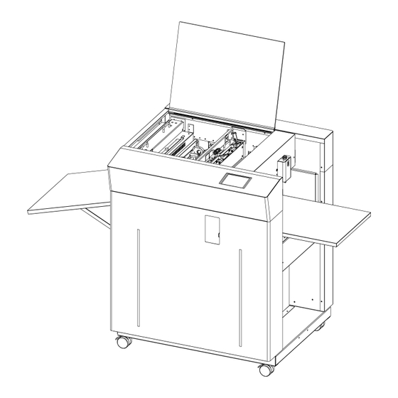
Page 9: Exterior Features
(2) Exterior features 1. Name of parts 1. Slitter 6. Feed Table 2. Stacker 7. Touch Panel 3. Waste Box 8. Adjustment Door 4. Safety Cover 9. Caster 5. Perforator cartridge 8... - Page 10 2. Electric-power-related points The electric power switch and the inlet are located inside the machine, below the feed table. ① When it is set at “I”, the power is turned on. Power switch ② When it is set at “O”, the power is turned off. Plug in the electric power cord here.
-
Page 11: Installation
(3) Installation machine installation method Please be sure to LOCK a caster brake after making it move to the target position, when installing a machine. Unlock Lock Caution When you install a machine, please install to a place with no dust, and the place which is not influenced with a liquid. -
Page 12: Operating Instructions
2. Operating instructions (1) Checks before use Check the following before operation. ① Is the electric power turned off? ② Is the feed table set? ③ Is the stacker set? ④ Is the electric power cord plugged in? ⑤ Is the waste box set? (2) Setting of stacker Paper Guide (Large) Indentation... -
Page 13: Waste Box Setting
(3) Waste box setting ① Set the waste box under the stacker. Stacker Chute Waste box Caution Power it off. Otherwise, Injury could occur. (4) How to attach the business card stacker. ① Hang the business card stacker on Paper ejection port of Stacker panel. ②... -
Page 14: Paper Setting
(5) Paper setting ① Press SET to lower the feed table. ② Separate the sheets of paper well and place them on the feed table. ③ Fix the paper with the small paper guides. ④ Make sure that the paper stack does not exceed the MAX label. MAX Label Paper Guide (Small) Caution... -
Page 15: Paper Slant Adjustment
(6) Paper slant adjustment ① Open the adjustment door on the front side of the main body. ② When the printing is tilted, turn the dial as shown in the drawing below to make it straight. ③ Turning the dial up will tilt the paper to the right, whereas turning it down will tilt the paper to the left. -
Page 16: Paper Feed Detection Plate Adjustment
(8) Paper feed detection plate adjustment ① Use the paper feed detection plate adjustment dial for this adjustment. ② Turn it counterclockwise (down) when the paper tends to be doubly fed, and turn it clockwise (up) when the paper is not smoothly fed. ③... -
Page 17: Crease Depth Adjustment
(10) Crease depth adjustment ① The sign shown in the drawing below will be displayed when using the creaser. ② Turn the dial shown in the drawing below to adjust the crease depth. ③ The depth will become the most shallow by choosing Level 1 and the deepest by choosing Level 5. -
Page 18: How To Remove The Crease Unit
(11) How to remove the crease unit ① Power it off. ② Be sure to hold the upper handles of the crease unit with both hands. Pushing it to the far side, lift the handle on the near side to remove the upper part of the crease unit. ③... -
Page 19: How To Attach The Perforator
(12) How to attach the perforator ① Power it off. ② Be sure to hold the perforator with both hands and attach it as shown in the figure. ③ Attach it in such a manner that the projection is positioned as shown in the figure. ④... -
Page 20: How To Adjust The Perforation Location
(13) How to adjust the perforation location ① When using the perforator, the screen will display where to fix the perforator, as shown below. ② If the upper blades are positioned to come into contact with the lower blades, the upper blade position can be adjusted with the perforator attached to the main body. - Page 21 ⑤ If the upper blades are not positioned to come into contact with the lower blades, remove the perforator from the main body for adjustment. ⑥ Remove the perforator in the reverse order of the procedure described in (12) (How to attach the perforator).
-
Page 22: How To Adjust The Depth Of Perforation
(14) How to adjust the depth of perforation ① Change in the paper thickness, recommend you adjust the depth of Perforation. ② The height of the upper blades can be individually adjusted. ③ Remove the perforator by reversing the procedure described in (12) (How to attach the perforator). -
Page 23: How To Replace The Perforation Lower Blade
(15) How to replace the perforation Lower Blade ① As the lower blades of the perforator repeatedly cut the paper, the paper finish condition degrades. ② If this is the case, shift the lower blade position slightly. ③ If the lower blades cannot be shifted any more, it is necessary to replace them. ④... -
Page 24: Operational Method
3. Operational method (1) Basic operation ① Turning the power on. ② Slitter initial location movement (When turning the power on initially and after adjusting the head location) ③ Format selection/free entry, user program retrieval, etc. ④ Slitter and table setting ⑤... -
Page 25: Format Selection
(3) Format selection ① Press PRESET. Operation Screen ② Select the paper type to be used. Paper Selection Screen 24... - Page 26 ③ Select the cutting pattern. Move to Cutting Pattern Confirmation Screen Confirm cutting pattern and Cutting Pattern move to Operation Screen Selection Screen Cutting pattern switching Return to Paper Selection Screen ④ Cutting pattern content confirmation and partial correction Press A through N to make corrections. O, P and Q are automatic calculations. It is possible to enter in inches up to the 3rd decimal place.
- Page 27 Number of pieces in the depth direction Number of pieces in the feeding direction Cutting Pattern Confirm cutting pattern and move to Operation Confirmation Screen Screen Return to Cutting Pattern Selection Screen Please use as a calculator Confirm input Crease Pos. value and return Input Screen Cancel input value...
-
Page 28: Free Entry
(4) Free entry ① Press MANU SET. Operation Screen ② The operation is almost the same as (3)-④. Move to User Program Cutting Pattern Selection Screen Correction Screen Move to User Program Selection Screen Confirm cutting pattern and move to Operation Screen Line is the number of It turns automatically into... -
Page 29: User Program Retrieval (Manu Set)
(5) User program retrieval (MANU SET) ① 60 user program can be registered. ② Press the button of the name you wish to retrieve. Move to the previous 10 program Move to the next 10 User Program program Selection Screen Return to Cutting Pattern Correction Screen ③... -
Page 30: User Program Registration (Manu Set)
(6) User program registration (MANU SET) ① 60 user program can be registered. ② Press the button in which you wish to make a registration. Move to the previous 10 program Move to the next 10 User Program program Selection Screen Return to Cutting Pattern Correction Screen ③... - Page 31 Uppercase/lowercase switching Finalize the registration name Cancel the entry and return overwriting Return to User Program Delete and move to Return to User Program move to Cutting Pattern Detail Screen User Program Detail Detail Screen Correction Screen Screen 30...
-
Page 32: Flex Entry
(7) FLEX entry ① Press FLEX MODE. Operation Screen ② This input screen allows you to freely select the guillotine or the crease up to 20 pitches for the paper of non-identical size unacceptable in the MANUSET screen, paper with special cutting patterns, and paper completely passing through. - Page 33 ③ This screen allows you to input each pitch from No. 1 to No. 20. The adjacent switches are used for selecting no operation, guillotine, or creaser. Every time the switch is pressed, the selected operation changes. :No operation :Guillotine :Crease ④...
- Page 34 ⑥ When letting the paper pass through completely (when passing only via the perforator or when using as the feeder), input the paper size for A and B, and the same dimension as B for D. Input “0” for all the remaining dimensions. ⑦...
-
Page 35: User Program Retrieval (Flex Mode)
(8) User program retrieval (FLEX MODE) ① 30 user program can be registered. ② Press the button of the name you wish to retrieve. Move to the previous 10 program Move to the next 10 User Program program Selection Screen Return to Cutting Pattern Correction Screen ③... -
Page 36: User Program Registration (Flex Mode)
(9) User program registration (FLEX MODE) ① 30 user program can be registered. ② Press the button in which you wish to make a registration. Move to the previous 10 program Move to the next 10 User Program program Selection Screen Return to Cutting Pattern Correction Screen ③... - Page 37 Uppercase/lowercase switching Finalize the registration name Cancel the entry and return overwriting Return to User Program Delete and move to Return to User Program move to Cutting Pattern Detail Screen User Program Detail Detail Screen Correction Screen Screen 36...
-
Page 38: Setting Of Slitter And Feed Table
(10) Setting of slitter and feed table ① By pressing SET, the feed table will be lowered to the bottom dead point and the slitter will move to the operating position. ② The display will change from SET to START upon completion. Operation Screen (11) Operation number cancellation... -
Page 39: Manual Operation And Speed Change
(12) Manual operation and Speed Change ① Press MANUAL SPEED. Operation Screen ② Use it when operating manually. ③ There are eight feeding speed levels. The currently selected speed level is inverted to black. Thick paper should not be fed at higher speeds. Please slow the speed down if sheet stops with noise associated. -
Page 40: Cut Mark On/Off Selection
④ To avoid double feed or skew feed, adjust PAPER FEED WORK TIME and volume of AIR BLOW. SHORT LONG 0.5s~5.0s Double feed: Double feed: more likely to occur less likely to occur PAPER FEED WORK TIME Skew feed: Skew Feed: less likely to occur more likely to occur BLOW OFF... -
Page 41: Automatic Operation
(14) Automatic operation ① Set the number of sheets for operation. The machine will automatically stop on reaching the set number. Enter “0” for continuous operations. User program job number and job name you have retrieved is displayed. Enter the number of sheets for operation. -
Page 42: Instructions For Use
4. Instructions for use (1) If the machine stops during operation ① If the machine stops during operation due to an error such as a paper jam and overloading, paper may still be left in the machine. ② In such a case, the paper must be removed by manual operation, as continuing to operate it may cause a mechanical failure ③... -
Page 43: If Paper Scrap Remains On The Machine
(2) If Paper scrap remains on the machine ① When the paper jams near the stacker panel or when maintenance work is done, the stacker panel can be opened. ② Shift the right and left lock levers of the stacker panel to the inner side, and pull the upper part by hand to open. -
Page 44: Details Concerning Errors
(3) Details concerning errors ① Paper size error Correct the paper size to fit in the value range below. ② Final cutting measurement error Correct the final cutting measurement to exceed the value specified below. ③ Cutting measurement error Correct the cutting measurement to fit in the value range below. The maximum value is subject to change depending on the entered paper size. - Page 45 ⑥ Top margin error Correct the top margin to fit in the value range below. ⑦ Back margin error (MANU SET) Correct the back margin to fit in the value specified below. ⑧ Back margin error (FLEX MODE) Correct the back margin to fit in the value specified below. ⑨...
- Page 46 ⑪ Perforation location warning Correct the perforation location to fit in the value range below. The maximum value is subject to change depending on the entered paper size. ⑫ Leading edge margin and cut mark margin warning Correct the measurement so that the leading margin becomes larger than the cut mark margin.
- Page 47 ⑯ Timeout error 2 Paper did not pass through within a set time period. Remove the paper remaining inside the machine. ⑰ Overload error 1 Cutting or creasing did not complete within a set time period. Remove the paper remaining inside the machine. ⑱...
- Page 48 Double feed detection error Double feed detected. Check the paper or paper path. Slitter units positioning error Slitter position is out of valid range. Check paper size and input data. Serial communication error Communication with the touch panel is not possible. Turn off the power, and turn it on again after 5 seconds or longer.
- Page 49 Data aren’t updated error This error message appears as a warning when proceeding to another screen without saving the corrected dimensions in the MANU SET or FLEX MODE screen. Press OK if you want to proceed to the other screen; otherwise, press RETURN. FLEX MODE input error This error results when the three input values shown in the following figure are “0”...
-
Page 50: If The Cut Measurement Does Not Match The Input Value
(4) If the cut measurement does not match the input value ① If Measurement A is different: When the input value is 0.200” and the actual cut measurement is 0.175”, input +0.025”; input -0.040” when the actual cut measurement is 0.240”. -
Page 51: Product Specifications
5. Product specifications Specifications Slitter 4 sets (6 slitter blades) Creaser 1 set (5-level manual crease depth adjustment) Perforator 2 sets Number of guillotine or creasing MAX48times / sheet 8.25” (A4 short) ~14.375” (B3 short) Paper size (depth direction) 8.25” (A4 short) ~20.500” (B3 long) Paper size (feed direction) Finish size MIN1.97”W×2.165”D... - Page 52 51...
-
Page 53: Equipment, Electric Circuit And Parts
6. Equipment, Electric circuit and parts 52... - Page 54 53...
- Page 55 54...
-
Page 56: Ordering Consumables, Etc
7. Ordering consumables, etc. When ordering consumables or parts, be sure to specify the machine model. 55... - Page 57 56...
- Page 58 If this “Operation Manual” is stained or lost, make contact with the distributor or our salesman or customer service section to ask for a new operation manual after making sure of its contents. UCHIDA YOKO CO., LTD. 57...
Need help?
Do you have a question about the AEROCUT G2 and is the answer not in the manual?
Questions and answers