
Related Manuals for WAGNER TwinControl


Summary of Contents for WAGNER TwinControl
-
Page 1: Twincontrol
Version 10/2018 TwinControl Electronically Controlled 2K Systems for Lacquers Valid for systems with software version V 4.xx 0102... -
Page 3: Table Of Contents
Electrical Devices and Equipment 4.1.2 A Safe Work Environment 4.1.3 Personnel Qualifications Safety Instructions for the Personnel 4.2.1 Personal Safety Equipment 4.2.2 Safe Handling of WAGNER Spray Devices 4.2.3 Grounding the Unit 4.2.4 Product Hoses 4.2.5 Cleaning and Flushing 4.2.6 Touching Hot Surfaces 4.2.7... - Page 4 Pneumatic Connections 6.4.2 Product Connections Grounding 6.5.1 Grounding of Components on Frame or Trolley 6.5.2 Example of Grounding Scheme for TwinControl with Turbine 6.5.3 Example of Grounding Scheme for TwinControl with Mains Power Connection (Cable) Commissioning 6.6.1 Preparation Before Commissioning 6.6.2...
- Page 5 8.13.1 Manual External Mixers DN2.6 and DN4 8.13.2 Manual External Mixer DN 8 8.14 Remote Control and ESTA Remote Control (Option) 8.14.1 Explosion Protection 8.14.2 TwinControl Remote Control 8.14.3 ESTA Remote Control 8.15 2A Switchbox for Second A-Pump (Option) CLEANING AND MAINTENANCE Cleaning 9.1.1...
- Page 6 VERSION 10/2018 ORDER NUMBER DOC 2339321 TROUBLESHOOTING 10.1 Alarm Messages and Fault Rectification REPAIRS 11.1 Repair Personnel 11.2 Repair Notes 11.3 Assembly Aids DISPOSAL ACCESSORIES 13.1 Mixer 13.2 Remote Control 13.3 Horn Alarm 13.4 Suction Hoses 13.5 Mixing Hoses 13.6 13.7 Heater 13.8...
-
Page 7: About These Instructions
VERSION 10/2018 ORDER NUMBER DOC 2339321 ABOUT THESE INSTRUCTIONS PREFACE The operating manual contains information about safely operating, maintaining, cleaning and repairing the device. The operating manual is part of the device and must be available to the operating and service personnel. -
Page 8: Languages
Additional languages on request or at: www.wagner-group.com Spare parts for the TwinControl systems and TwinControl accessories are to be found in two separate spare parts catalogs. The catalogs are available in the following languages: Spare parts catalog for TwinControl Finishing... -
Page 9: Twincontrol Cd
ZZB019ENG Spanish ZZB019SPA French ZZB019FRE Italian ZZB019ITA TWINCONTROL CD All operating documents specified previously are also available as PDF files on a compact disk (CD). The CD is included in the system's scope of delivery. The order no. is: 2339342... -
Page 10: Abbreviations
VERSION 10/2018 ORDER NUMBER DOC 2339321 ABBREVIATIONS Abbreviations in the text Number of pieces TC 1.4404 TwinControl for acidic hardeners Position Protective coating: heavy duty corrosion protection Marking in the spare parts lists High pressure 4-50 MPa; 40-500 bar; 580-7,250 psi Order no. -
Page 11: Correct Use
WAGNER explicitly prohibits any other use! The device may only be operated under the following conditions: Use the device only to work with the products recommended by WAGNER. Do not deactivate safety fixtures. Use only WAGNER original spare parts and accessories. -
Page 12: Processible Working Materials
- 2K PUR lacquers - 2K high-solid lacquers - 2K products with acidic hardeners (only with TwinControl systems for acidic hardeners) Solvent and water-based 2K products should not be processed using the same system. Materials in direct contact with the products: see Chapter 5.5.1... -
Page 13: Identification
VERSION 10/2018 ORDER NUMBER DOC 2339321 IDENTIFICATION EXPLOSION-PROOF MARKING FOR DEVICES WITH TURBINES – Turbines As defined in the Directive 2014/34/EU (ATEX), the TwinControl control unit (turbine) is suitable for use in potentially explosive areas. Device type: TwinControl Manufacturer: Wagner International AG 9450 Altstätten... -
Page 14: Use In Areas Subject To Explosion Hazards
VERSION 10/2018 ORDER NUMBER DOC 2339321 3.1.1 USE IN AREAS SUBJECT TO EXPLOSION HAZARDS Safe Handling of WAGNER Spray Devices Mechanical sparks can form if the device comes into contact with metal. In an explosive atmosphere: Do not knock or push the device or components and tools against steel or rusty iron. -
Page 15: Identification For Devices With A Mains Power Supply
The remote control (accessory) may not be used along with a system with a mains power supply (cable) in potentially explosive areas. The same applies to the 2A switchbox (accessory). Device type: TwinControl Manufacturer: Wagner International AG 9450 Altstätten Switzerland Identification: CE mark (European Communities) -
Page 16: Type Plates
VERSION 10/2018 ORDER NUMBER DOC 2339321 TYPE PLATES – Turbines 1 Manufacturer 2 Device type: TwinControl Wagner International AG Made in Switzerland CH 9450 Altstätten 3 Serial number of system TwinControl Type / Typ: 4 CE identification 5 Year of manufacture Serial No unit.:... -
Page 17: Basic Safety Instructions
VERSION 10/2018 ORDER NUMBER DOC 2339321 BASIC SAFETY INSTRUCTIONS SAFETY INSTRUCTIONS FOR THE OPERATOR Keep this operating manual at hand near the device at all times. Always follow local regulations concerning occupational safety and accident prevention. 4.1.1 ELECTRICAL DEVICES AND EQUIPMENT Electric shock hazard! Danger to life from electric shock Prepare device in accordance with the local safety requirements with regard to the... -
Page 18: Personnel Qualifications
VERSION 10/2018 ORDER NUMBER DOC 2339321 Ensure that personal protective equipment (see Chapter 4.2.1) is available and is used. Ensure that all persons within the working area wear static dissipative shoes. Footwear must comply with EN 20344. The measured insulation resistance must not exceed 100 MΩ. -
Page 19: Personal Safety Equipment
"Troubleshooting" chapter. If needed, the liquid ejection devices must be checked by experts (e.g., WAGNER service technician) at least every 12 months for their work-safe condition in accordance with DGUV regulation 100-500 Chapter 2.29 and Chapter 2.36. – For shut down devices, the examination can be suspended until the next start-up. -
Page 20: Grounding The Unit
VERSION 10/2018 ORDER NUMBER DOC 2339321 4.2.3 GROUNDING THE UNIT Hazard due to electrostatic charge! Explosion hazard and damage to the device. Friction, flowing liquids and air or electrostatic coating processes create charges. Flames or sparks can form during discharge. Correct grounding of the entire spraying system prevents electrostatic charges. -
Page 21: Cleaning And Flushing
VERSION 10/2018 ORDER NUMBER DOC 2339321 Several liquids have a high expansion coefficient. In some cases, their volume can rise with consequent damage to pipes, fittings, etc. and cause fluid leakage. When the pump sucks liquid from a closed tank, ensure that air or a suitable gas can enter the tank. -
Page 22: Touching Hot Surfaces
4.2.7 MAINTENANCE AND REPAIR Hazard due to improper maintenance and repair! Danger to life and equipment damage. Only a WAGNER service center or a suitably trained person may carry out repairs and replace parts. Use only WAGNER original spare parts and accessories. -
Page 23: Description
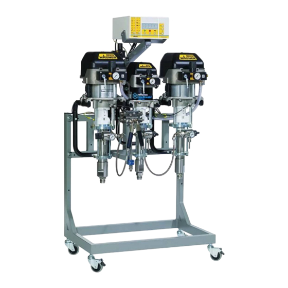
ORDER NUMBER DOC 2339321 DESCRIPTION COMPONENTS B_02796 B_02798 B_04563 Designation Designation 1 Pneumatic pump for A-component 5 Frame 2 Flushing pump "S" 6 Mixing unit 3 Pneumatic pump for B component 7 Trolley 4 TwinControl control unit 8 Wall mount... -
Page 24: Twincontrol Finishing And Protective Coating
* 5-60 not on trolley MODE OF OPERATION The TwinControl system consists of 5 function units: The pneumatically operated high-pressure pumps for A and B components and for flushing agents, the mixing unit and the control unit. The two product components are brought to high-pressure by the pumps and an adjustable, predefined mixing ratio is intermixed in the static mixer, from where it is conveyed to the spray gun. -
Page 25: Included Items
CE Declaration of Conformity See Chapter Operating manual, in German 2339287 Operating manual in the local language See Chapter TwinControl compact disc (CD, see Chapter 1.4) 2339342 Instruction sheet – transportation 2305117 Supplement for TwinControl with password protection 2304064 The delivery note shows the exact scope of delivery. -
Page 26: Control Units With Turbines
VERSION 10/2018 ORDER NUMBER DOC 2339321 5.5.2 CONTROL UNITS WITH TURBINES Unit TwinControl control units with turbines Minimum/maximum input air pressure MPa; bar; psi 0.6–0.8; 6–8; 87–116 Nominal air consumption NL/min °C +5 ... +40 Permissible ambient temperature range °F +41 ... - Page 27 The maximum permitted cable length is 75 m; 246 ft. 11. If the complete TwinControl system is operated as part of a water varnish coating system connected to high voltage, the green-yellow ground cables must be removed and replaced with black cables with the same cross-section.
-
Page 28: Control Units With Mains Power Supply (Cable)
VERSION 10/2018 ORDER NUMBER DOC 2339321 5.5.3 CONTROL UNITS WITH MAINS POWER SUPPLY (CABLE) TwinControl control units with cable Unit connection Input voltage 85–260 Input power maximum 40 Input frequency 47-440 +5 < Ta < +40 Permissible ambient temperature range +41 <... - Page 29 – Correct use of the system in accordance with the specific operating conditions such as the permitted product and ambient temperature, suitable viscosity and flow rate. – Regular maintenance has to be carried out by a qualified person (e.g., WAGNER service technician) in accordance with Chapter 9.2.
-
Page 30: Pumps
VERSION 10/2018 ORDER NUMBER DOC 2339321 5.5.5 PUMPS EvoMotion / Wildcat / Puma Unit Pump ratio 10:1 18:1 28:1 15:1 15:1 21:1 8:1 Volume flow per double stroke cm3; cc 110 300 600 14.4 22.4 16.8 6.4 Maximum product pressure on mixer ** 2089 3249 1740 2436 928 348... -
Page 31: Dimensions
VERSION 10/2018 ORDER NUMBER DOC 2339321 5.5.6 DIMENSIONS B_04488 TwinControl on small frame EvoMotion, Wildcat, Puma, Pumps Leopard without with heater heater A + B mm; inch mm; inch 860; 33.9 1205; 47.5 1551; 61.1 550; 21.7 TwinControl on large frame... - Page 32 VERSION 10/2018 ORDER NUMBER DOC 2339321 TwinControl on wall Type 28-40 15-70 15-150 21-110 8-300 3-600 35-70 35-150 48-110 18-300 8-600 mm; inch 917; 36.1 1022; 1005; 1020; 1187; 1202; 1015; 1183; 1197; 1243; 48.9 1239; 48.8 40.2 39.6 40.2 46.7...
-
Page 33: Weights
VERSION 10/2018 ORDER NUMBER DOC 2339321 TwinControl on small trolley Pumps Wildcat, Puma, Leopard without with heater heater A + B mm; inch mm; inch 820; 32.3 899; 35.4 1787; 70.4 1225; 48.2 1243; 48.9 TwinControl on large trolley Pumps... -
Page 34: Overview Of Twincontrol Controllers
VERSION 10/2018 ORDER NUMBER DOC 2339321 OVERVIEW OF TWINCONTROL CONTROLLERS Control A-pumps = 5-60, 10-70, 28-40, 15-70, 15-150, × × × × × × × 21-110, 35-70, 35-150 A-pumps = 48-110, 75-150, 55-200, 8-300, × × × × 38-300, 72-300, 3-600,18-300, 8-600 Circulation A, B ×... -
Page 35: Principle Diagram
Controllers 1 / 9 / 10 for turbine: The turbine generates the current from compressed air. Controller 1 for cable: Controller with electrical mains connection. For differences in controllers 1, 9 and 10: see Chapter TwinControl TwinControl Controllers 1 / 9 / 10... -
Page 36: Controllers 2 / 3 / 6 / 8 For Pumps 48-110 To
Controllers 2 / 3 / 6 / 8 for turbine: The turbine generates the current from compressed air. Controllers 2 / 3 for cable: Controller with electrical mains connection. For differences in controllers 2, 3, 6 and 8: see Chapter TwinControl TwinControl Controllers 2 / 3 / 6 / 8... -
Page 37: Operating Elements And Control Unit Connections
VERSION 10/2018 ORDER NUMBER DOC 2339321 OPERATING ELEMENTS AND CONTROL UNIT CONNECTIONS Front side The front side of the TwinControl control unit is the same on all 6 device variants. 128 126 127 125 TwinControl B_02601 Designation Designation 101 Push button [Start]... - Page 38 Check manual before use! IP 54 Schutzart: Vor Gebrauch Betriebsanleitung present. beachten! B_02811 Rear side TwinControl control unit with cable connection Made in Switzerland Wagner International AG CH 9450 Altstätten TwinControl Type / Typ: Year of construction / Baujahr: Serial No unit.: Serie Nr.
-
Page 39: Pneumatic Diagram
VERSION 10/2018 ORDER NUMBER DOC 2339321 PNEUMATIC DIAGRAM 5.9.1 TWINCONTROL 1 (option) (option) Control air Mains air B_07283 Connection numbers for control unit 1 (on rear side) Further designations Designation Designation Product valve A Air supply Hardener valve B System compressed air monitoring... - Page 40 VERSION 10/2018 ORDER NUMBER DOC 2339321 5.9.2 TWINCONTROL 2 / TWINCONTROL 3 (option) (TwinControl 2: option) Control air Mains air B_07284 Connection numbers for control units 2 / 3, rear side Connection numbers for control units 2 / 3, rear side...
- Page 41 VERSION 10/2018 ORDER NUMBER DOC 2339321 5.9.3 TWINCONTROL 6 / TWINCONTROL 8 Control air Mains air (internal) (internal) Connection numbers for control units 6 / 8, rear side Connection numbers for control units 6 / 8, rear side Designation Designation...
- Page 42 VERSION 10/2018 ORDER NUMBER DOC 2339321 5.9.4 TWINCONTROL 9 / TWINCONTROL 10 From software version 4.2x Only (option) TwinControl 10 TwinControl 9: TwinControl 9: TwinControl 10: TwinControl 10: TwinControl 9: TwinControl 9: TwinControl 10: TwinControl 10: Control air Mains air...
-
Page 43: List Of Service Functions
VERSION 10/2018 ORDER NUMBER DOC 2339321 5.10 LIST OF SERVICE FUNCTIONS Software version V 4.0x / 4.1x / 4.2x Unit Description Filling Mixed product in the hose Adjustable Volume A product from product valve to mixing block Adjustable Volume B product from product valve to mixing block Adjustable Flushing recipes 1 or 2... - Page 44 VERSION 10/2018 ORDER NUMBER DOC 2339321 Software version V 4.0x / 4.1x / 4.2x Unit Description P120 Front display in mixing mode and/or if gun is closed: 0 = mixing ratio (MR); Adjustable 1 = flow rate or pot life (F_P); 2 = job sum (JS); 3 = MR and F_P in turn; 4 = MR and JS in turn;...
- Page 45 VERSION 10/2018 ORDER NUMBER DOC 2339321 Software version V 4.0x / 4.1x / 4.2x Unit Description P150 0 = No calibration in mixing mode. Adjustable 1 = Calibration in mixing mode (A-valve is in mixing block and is not opened). 2 = Calibration in mixing mode (A-valve is not in mixing block and is opened).
-
Page 46: Dry Running Protection
(as of version 4.03) to a VM 5000 control unit. If the electrostatic system for the gun may be switched on (after filling), the TwinControl system transmits the pneumatic approval signal to the pressure switch. The pressure switch switches at a set pressure of, e.g., 2 bar. -
Page 47: Connection Kit For Gun Flush Box (Option)
ORDER NUMBER DOC 2339321 5.15 CONNECTION KIT FOR GUN FLUSH BOX (OPTION) The GFB connection kit is used as a link between the TwinControl system and a gun flush box. The installed connection kit records the following test functions: - is a gun used in the gun flush box, - is the GFB lid closed, - is the gun in the gun flush box for flushing open. -
Page 48: Evomotion 5-125 Feed Pump
3. Consecutively for each pump. – Switch off the compressed air supply (close ball valve). – TwinControl control unit: Select "Work" in main menu. Select the respective components (e.g., "A") in the sub-menu and push [Start]. – Relieve the respective pump of pressure in accordance with pump's operating manual. -
Page 49: Assembly And Commissioning
VERSION 10/2018 ORDER NUMBER DOC 2339321 ASSEMBLY AND COMMISSIONING TRAINING OF ASSEMBLY/COMMISSIONING PERSONNEL The assembly and commissioning personnel must have the technical skills to safely commission the device. When assembling, commissioning and carrying out all work, read and follow the operating manuals and safety regulations for the additionally required system components. -
Page 50: Transportation
VERSION 10/2018 ORDER NUMBER DOC 2339321 TRANSPORTATION The complete system can be safely transported in a wooden crate. The dimensions of the transport crate can be defined with the help of the information on device dimensions in Chapter 5.5.6. Weights for sample configurations can be found in Chapter 5.5.7. -
Page 51: Assembly And Installation
VERSION 10/2018 ORDER NUMBER DOC 2339321 ASSEMBLY AND INSTALLATION The system is installed and commissioned by the WAGNER service department or by an expert representative. When removing from the packaging, check the system parts for possible transport damage. WARNING Electric shock hazard inside the control unit! Danger to life from electric shock. -
Page 52: Pneumatic Connections
Do not clean the tank on the filter pressure regulator with solvents. 6.4.2 PRODUCT CONNECTIONS Fit suction systems in accordance with operating manuals for pumps. Connect high-pressure hose and gun to the TwinControl mixer unit as laid down in the operating manual for the gun. -
Page 53: Grounding
VERSION 10/2018 ORDER NUMBER DOC 2339321 GROUNDING DANGER Discharge of electrostatically charged components in atmospheres containing solvents! Explosion hazard from electrostatic sparks or flames. Ground all device components. Ground the work pieces to be coated. WARNING Danger due to fire, explosion and electric shock hazard! Danger to life through electric shock and explosion. -
Page 54: Grounding Of Components On Frame Or Trolley
VERSION 10/2018 ORDER NUMBER DOC 2339321 6.5.1 GROUNDING OF COMPONENTS ON FRAME OR TROLLEY View of rear side of system J. Wagner AG Made in Switzerland CH 9450 Altstätten Type / Typ: TwinControl Grounding connections Serial No unit.: Serie Nr. Anlage:... -
Page 55: Example Of Grounding Scheme For Twincontrol With Turbine
7 Floor, static dissipative 9 Remote control (option) 4 Paint tank 6 Conveyor 8 Flushing agent tank 10 Horn (option) 6.5.3 EXAMPLE OF GROUNDING SCHEME FOR TWINCONTROL WITH MAINS POWER CONNECTION (CABLE) Non-Ex zone Ex zone 1 and 2 ... -
Page 56: Commissioning
VERSION 10/2018 ORDER NUMBER DOC 2339321 COMMISSIONING 6.6.1 PREPARATION BEFORE COMMISSIONING Make sure that the device and all other conductive parts within the work area are grounded. Connect spray gun without nozzle with high-pressure hose to the mixing unit and secure with safety clip. -
Page 57: Basic Flushing And Pressure Tightness Test
VERSION 10/2018 ORDER NUMBER DOC 2339321 6.6.2 BASIC FLUSHING AND PRESSURE TIGHTNESS TEST The devices are tested in the factory with emulsifying oil, pure oil or solvent. Possible residues must be flushed out of the circuits with a solvent (flushing agent) before commissioning. WARNING Incompatibility of flushing agent and working media! Risk of explosion and danger of poisoning by toxic gases. - Page 58 VERSION 10/2018 ORDER NUMBER DOC 2339321 7.7. Point the spray gun (preferably without nozzle) into the grounded metal tank for return product and open carefully. 7.8. Slowly open ball valve of pump A. Be ready to switch from air to flushing agent and prevent back spray.
- Page 59 VERSION 10/2018 ORDER NUMBER DOC 2339321 – Relieve air pressure in accordance with the operating manual for pump B. – Slowly open the return valve of pump B. When no further overpressure is detected, close the return valve again. – Point the spray gun into the grounded metal tank for return product. –...
-
Page 60: Replacing Flushing Agent With Working Media
VERSION 10/2018 ORDER NUMBER DOC 2339321 6.6.3 REPLACING FLUSHING AGENT WITH WORKING MEDIA NOTICE Interchange of the two components A and B! Device damage due to hardened product. Label device components and paint tank so that the components A and B are not mixed up. - Page 61 VERSION 10/2018 ORDER NUMBER DOC 2339321 7.10. Relieve pressure of A-product-circuit: – Relieve air pressure in accordance with the operating manual for pump A. – Slowly open the return valve of pump A. When no further overpressure is detected, close the return valve again. –...
-
Page 62: Calibrating The System
VERSION 10/2018 ORDER NUMBER DOC 2339321 6.6.4 CALIBRATING THE SYSTEM Calibrating A-component Calibrating B-component TwinControl TwinControl B_02744 B_02744 The system is volumetrically calibrated in the factory, therefore it does not have to be calibrated with the product. However, if a calibration is required, proceed as follows: 1. - Page 63 VERSION 10/2018 ORDER NUMBER DOC 2339321 6.6.4.1 METHOD OF CALIBRATION (SIMPLE PRACTICAL VARIANT) 1. Manually measure precisely e.g., 500 cm of A-product into a measuring cup and determine the product weight in "g" grams. Note: For pumps with more than 150 cm a greater product reference quantity must be specified.
- Page 64 1000 e.g., weigh out 500 cm (= 0.5 liter) of A-product. 610.00 Set calibration A on the control unit. TwinControl TwinControl Once 610 g has been discharged, enter 500 on the control unit and confirm with [SET]. Tubing to protect...
-
Page 65: Controller
VERSION 10/2018 ORDER NUMBER DOC 2339321 CONTROLLER TRAINING THE OPERATING PERSONNEL The operating personnel must be qualified to operate the entire system. The operating staff must be familiar with the potential risks associated with improper behavior as well as the necessary protective devices and measures. Before work commences, the operating personnel must receive appropriate system training. -
Page 66: Operating The Control Unit
OPERATING THE CONTROL UNIT For the meaning of all symbols/illuminated displays: see Chapter Main menu Sub-menu Display Alarm Pot life Tasks TwinControl B_02744 Setting buttons [Flush] button [Stop] button [Start] button Menu selection buttons Base position When switched on, the control unit is in its base position. The three lamps "Work", "A" and "B"... -
Page 67: Entering Numbers [Set]
[SET], [+] (higher) or [-] (lower) Terminate data input [Stop] button To save numbers [SET] Into main menu 2x [Stop] button If the indication "OFF" appears after making an entry in the display, then the input authorization must be enabled. TwinControl B_02744... -
Page 68: Password Protection And User Functions
Exceptions: Parameters P107, P108, P109, P110, P111, P112, P308 and P309 can be viewed only. The passwords, which are set by WAGNER at the time of the device delivery, are not contained in the operating manual for safety reasons. The valid passwords are communicated to the... -
Page 69: Basic Functions For The Painter
ORDER NUMBER DOC 2339321 BASIC FUNCTIONS FOR THE PAINTER Base position System is ready to start [Start] button-> system starts mixing TwinControl B_02744 System is mixing Pot life LED flashing -> pot life running Work LED flashing -> filling Work LED illuminated -> system ready to spray B-valve cycle display ->... -
Page 70: Extended Functions With Password Protection
Adjusting the mixing ratio Press [SET] -> change value with + - push button. Press [SET] again to confirm new value (Cancel with STOP push button). TwinControl B_02744 Manual operation / job quantities – Only convey A-component (START / STOP). - Page 71 ORDER NUMBER DOC 2339321 Total quantities – Total amount A Set to "0": Press [SET] push button > 2 seconds. Display in liters. TwinControl B_02744 – Total amount B Set to "0": Press [SET] push button > 2 seconds. Display in liters.
- Page 72 VERSION 10/2018 ORDER NUMBER DOC 2339321 Pot life Setting the pot life. set [SET] with [+] [-], [SET]. TwinControl B_02744 Error messages Display of last 28 error messages. View with ±. TwinControl B_02744 Circulation of A and B components (only possible if option available)
- Page 73 VERSION 10/2018 ORDER NUMBER DOC 2339321 Service (password entry required for P100) – Content of spray hose with mixed product TwinControl B_02744 – Quantity from product valve A to mixing block TwinControl B_02744 – Quantity from product valve B to mixing block...
-
Page 74: Calibration
5 double strokes into measuring cup -> Gun closed -> [SET] -> Enter measurement in measuring cup in cm -> [SET] (Cancel with [Stop] button) TwinControl B_02744 Calibrate B [Start] -> Open gun -> With spray pressure, pump out around 5 double strokes into measuring cup -> Gun closed -> [SET] ->... -
Page 75: Flushing Programs
Flushing program mode The flushing steps can be defined in the mode shown under parameters F1 to F20. TwinControl B_02744 Enter flushing program – Press [SET] during program step F1 (to F20). A appears on the left to enter the action. - Page 76 VERSION 10/2018 ORDER NUMBER DOC 2339321 Display in the display unit When the programmed flushing program is called up by pressing the [Flush] push button on the control unit and is running, each of the individual steps is shown briefly on the display.
-
Page 77: Ais
VERSION 10/2018 ORDER NUMBER DOC 2339321 7.6.3 AIS Prerequisite: AIS system The AIS (Adaptive Injection System) automatically regulates the dosing valve stroke. A stepping motor increases or decreases the stroke in steps. AIS settings (password level 4) Parameter Explanation Unit Values Default Number of dosing valve cycles after the AIS has performed... - Page 78 Observe for 3 minutes in spray mode with gun open: If the AIS position (P309) is continually counting up or down in the same direction without the opening time of the dosing valve (P308) changing, the AIS is not working. Contact the WAGNER service department. Check AIS stepping motor Check whether the AIS stepping motor works: 1.
-
Page 79: Check For Leaks In A And B Fluid Section
A-pump and B-pump (including circulation valves) are checked for leaks for 10 seconds. During the check, the display counts from 10 to 0 and the LED displays for A and B flash TwinControl alternately. Any leakage is indicated by an error message. B_02744 Changing stroke direction 4. -
Page 80: Batch Mode" Filling Mode
"Total" illuminated display must be flashing. Press [Set] -> the current set value is displayed. Use the [+] or [-] button to select the set value. Use [SET] to save the new set value. TwinControl B_02744 Operation Press [Start]. Note: If filling has not yet taken place, it is undertaken automatically. -
Page 81: Operation
SAFETY INSTRUCTIONS The operating documents for the pneumatic pumps and other system components should be read through carefully. The appropriate operating manuals are available on the WAGNER CD as PDF files. Also observe the operating manuals for the components mounted on site. -
Page 82: Malfunction
VERSION 10/2018 ORDER NUMBER DOC 2339321 MALFUNCTION If a fault occurs, it is indicated by the following: The system stops and the alarm horn sounds The alarm display lights up (control unit and remote control). A fault is indicated on the display. Acknowledge fault With the [Stop] button. -
Page 83: Switching The System On
VERSION 10/2018 ORDER NUMBER DOC 2339321 SWITCHING THE SYSTEM ON Return line B_04505 Example of TwinControl system ready for spraying... - Page 84 3. For a system with a product pressure regulator: Switch on the work air. B_02836 4. For a TwinControl cable variant: Turn on main switch on the control unit. B_02837...
-
Page 85: Switching Off The System
Switch of the work air. B_07212 5. Switch off air supply. B_07211 6. For a TwinControl cable variant: Switch off main switch on control unit. B_07213 7. Relieve compressed air pressure between main switch and pumps: – Flushing pump A: Open air ball valve –... -
Page 86: Spraying Mode
VERSION 10/2018 ORDER NUMBER DOC 2339321 SPRAYING MODE Optimum painting results are obtained if: − the system parameters are set correctly; − product data such as the mixing ratio and pot life correspond to the working product; − the flushing program is defined; −... -
Page 87: Flushing
VERSION 10/2018 ORDER NUMBER DOC 2339321 NOTICE Fluctuating supply pressures! Poor coating result. The supply pressure of component B should be adjusted to a higher value (approx. 5-10%) than that of component A. The supply pressures should be constant. FLUSHING The system's flushing program flushes the hoses between the mixer and gun and removes any mixed product present. -
Page 88: Pressure Relief / Work Interruption
– before the nozzle or the filter is removed from the spray gun. Procedure (password level 1 is required) 1. Close and secure the spray gun. 2. Press [Stop]. TwinControl B_02744 3. Relieve all A and B pumps of pressure: – Relieve air pressure in accordance with the respective operating manual. - Page 89 – Press [Flush]. – Point the spray gun (preferably without nozzle) into the grounded metal tank for return product. TwinControl B_02744 – Release the spray gun safety and open carefully. – Flush until clean flushing agent comes out and the flushing program is complete.
-
Page 90: Automatic Electrostatic System Set For Electrostatic Gun Gm5000 (Option)
The TC VM5000 automatic electrostatic system set serves as an additional safety device for the safe use of the TwinControl 2K system with a GM 5000 electrostatic gun. However, the operator has a duty to proceed in compliance with the following instructions. -
Page 91: Spraying Mode
3 and at no. 3- is pressurized (see Chapter and 5.9). 5. Press the "flushing" button or allow the TwinControl to undercut the pot life. As soon as the pot life alarm is triggered, electro-pneumatic valve no. 3 is actuated. The trigger mechanism of the gun flush box is now operated, i.e., is pressurized at connection no. -
Page 92: Soft Circulation (Option)
VERSION 10/2018 ORDER NUMBER DOC 2339321 8.12 SOFT CIRCULATION (OPTION) Working pressure Systems with soft circulation can automatically circulate the A and/or B component. During circulation, the pumps run at the preset, reduced circulation pressure. Circulation pressure Example, soft circulation Circulation valve Leopard GA 400... -
Page 93: External Mixers (Option)
VERSION 10/2018 ORDER NUMBER DOC 2339321 8.13 EXTERNAL MIXERS (OPTION) 8.13.1 MANUAL EXTERNAL MIXERS DN2.6 AND DN4 For A-pumps: 5-60, 10-70, 28-40, 15-70, 15-150, 21-110, 35-70, 35-150 Inputs: A, B and S components Switches A+B: Spray on/off Switch S: Flushing on/off (open position) Spraying mode Switches A+B open, switch S closed. -
Page 94: Remote Control And Esta Remote Control (Option)
The remote control may not be used along with a system with a mains power supply (cable) in potentially explosive areas. The TwinControl remote control may be used along with a system with a turbine in potentially explosive areas (zone 1, zone 2) (see Chapter 2.3). -
Page 95: Esta Remote Control
Electric cable: Connect reversing box to control unit (for RC connection, see Chapter 5.8). ESTA area Outside ESTA area completely electrostatically charged (1) Product valve A (3) Gun flush box (option) TwinControl (5) Circulation (option) control unit (6) Alarm Air supply ESTA remote... -
Page 96: Switchbox For Second A-Pump (Option)
VERSION 10/2018 ORDER NUMBER DOC 2339321 8.15 2A SWITCHBOX FOR SECOND A-PUMP (OPTION) TwinControl B_04508 If two different colors are to be used in turn, a second A-pump can be installed. A 2A switchbox is used to switch between pumps A1 and A2. The switchbox switches the following pump signals over and forwards them to the control unit: –... -
Page 97: Cleaning And Maintenance
VERSION 10/2018 ORDER NUMBER DOC 2339321 CLEANING AND MAINTENANCE CLEANING 9.1.1 CLEANING PERSONNEL Cleaning work should be undertaken regularly and carefully by qualified and trained personnel. They should be informed of specific hazards during their training. The following hazards may arise during cleaning work: –... -
Page 98: Cleaning The System
VERSION 10/2018 ORDER NUMBER DOC 2339321 9.1.4 CLEANING THE SYSTEM The system must be cleaned to change products and for maintenance purposes. Ensure that no remaining product dries on and sticks to the device. A cleaned system allows leaks to be found easily and measures to be taken quickly. Procedure 1. -
Page 99: Maintenance
WARNING Incorrect maintenance/repair! Danger to life and equipment damage. Only a WAGNER service center or a suitably trained person may carry out repairs and replace parts. Use only WAGNER original spare parts and accessories. Only repair and replace parts that are listed in the "Spare parts" chapter and that are assigned to the unit. -
Page 100: Safety Checks And Maintenance Intervals
In accordance with DGUV regulation 100-500 Chapter 2.29 and 2.36: – The liquid ejection devices should be checked by an expert (e.g., WAGNER service technician) for their safe working conditions as required and at least every 12 months. – For shut down devices, the examination can be suspended until the next start-up. -
Page 101: Non-Return Valves
VERSION 10/2018 ORDER NUMBER DOC 2339321 9.2.7 NON-RETURN VALVES Regularly check the function of the non-return valves. Pressure relief valve for protecting the feed pump (see Chapter 5.16) Regularly check the function of the pressure relief valve. The pressure-relief valve must be cleaned regularly and after each activation: Flush with solvent. -
Page 102: Cleaning Or Replacing The Product Filter
VERSION 10/2018 ORDER NUMBER DOC 2339321 9.2.10 CLEANING OR REPLACING THE PRODUCT FILTER 9.2.10.1 ANGLED INLINE FILTER (530 BAR) 1. Flush the pump and inline filter in accordance with Chapter 5.17 with pump's operating manual. Flush using the gun so that the flushing agent flows through the inline filter. Maximize the flow (remove the nozzle, open the dosing valve if necessary). - Page 103 VERSION 10/2018 ORDER NUMBER DOC 2339321 9.2.10.3 HIGH-PRESSURE FILTER, 530 BAR Filter installation position 1. Flush the pump and high-pressure filter in accordance with Turned over Chapter 5.17 and with pump's operating manual. Flush using the gun so that the flushing agent flows through the filter cartridge (F). Maximize the flow (remove the nozzle, open the dosing valve if necessary).
-
Page 104: Product Hoses, Pipes And Couplings
– 10 years from the date of the hose imprinting. Fitting embossing Meaning xxx bar Pressure yymm Crimping date (year/month) Internal code Hose imprinting Meaning WAGNER Name/Manufacturer yymm Date of manufacture (year/month) xxx bar (xx MPa) Pressure e.g., 270 bar (27 MPa) Internal code DNxx (e.g., DN10) Nominal diameter... -
Page 105: Troubleshooting
VERSION 10/2018 ORDER NUMBER DOC 2339321 10 TROUBLESHOOTING Fault display If a fault occurs, it is indicated by the following: The horn sounds and the system stops. The alarm display lights up (control unit and remote control). A fault is indicated on the display. Acknowledge fault With the [Stop] button. - Page 106 VERSION 10/2018 ORDER NUMBER DOC 2339321 Malfunction Remedy System does not start up – Check air supply line connection. – Check the pressure value on the system's pressure gauge for the air supply to the valves. – Check the voltage supply (Does the control panel light up?). –...
-
Page 107: Alarm Messages And Fault Rectification
VERSION 10/2018 ORDER NUMBER DOC 2339321 10.1 ALARM MESSAGES AND FAULT RECTIFICATION Software version V 4.0x / 4.1x / 4.2x Code Meaning Cause Fault rectification No authorization Unauthorized input Release authorization Shortage of the Too little B-component in the Increase air pressure for B pump or B-component mixture. - Page 108 Check product supply. Leak check, pump cavitating. check piston valve. Alarm password The software is not enabled. Enter software password. WAGNER AG password (only possible on PC). Incorrectly adjusted Turbine speed too low. Check turbine. Adjust air pressure air pressure (WAGNER technician).
- Page 109 Inspect B-valve. Failure The factory settings are not saved. Contact the WAGNER hotline. Failure The customer settings are not saved. Contact the WAGNER hotline. EEPROM alarm Reading or writing to the EEPROM Contact WAGNER service department. is not possible. ADC alarm Reading the potentiometer values Contact WAGNER service department.
-
Page 110: Repairs
WARNING Incorrect maintenance/repair! Danger to life and equipment damage. Only a WAGNER service center or a suitably trained person may carry out repairs and replace parts. Use only WAGNER original spare parts and accessories. Only repair and replace parts that are listed in the "Spare parts" chapter and that are assigned to the unit. -
Page 111: Assembly Aids
VERSION 10/2018 ORDER NUMBER DOC 2339321 DANGER Incorrect maintenance/repair! Danger to life and equipment damage. Repair or replacement of devices or parts of devices are only allowed to be performed outside the hazard area by qualified personnel. 11.3 ASSEMBLY AIDS In the spare parts catalog the order numbers for device spare parts can be found, as well as for wearing parts such as seals. -
Page 112: Disposal
WAGNER or one of our dealers will take back your used WAGNER electric or electronic equipment and will dispose of it for you in an environmentally-friendly way. -
Page 113: Accessories
VERSION 10/2018 ORDER NUMBER DOC 2339321 13 ACCESSORIES 13.1 MIXER Order no. Designation 2338297 Manual, external mixer DN 2.6 for A-pumps 5-60, 10-70, 28-40, 15-70, 15-150, 21-110, 35-70, 35-150 B_02977 Mixing tube 2339620 Automatic, external mixer DN 2.6 for A-pumps 5-60, 10-70, 28-40, 15-70, 15-150, 21-110, 35-70, 35-150 Prerequisite: Controller 3, 6 or 9... - Page 114 VERSION 10/2018 ORDER NUMBER DOC 2339321 2339617 Automatic, external mixer DN 4 / DN 10VA as of 48-110 for A-pumps 48-110, 8-300, 3-600, 18-300, 8-600, 75-150, 55-200, 38-300, 72-300 Prerequisite: Controller 3, 6 or 9 B_04486 2339628 Circulation G3/8" for automatic, external mixer DN 4 B_04497 2338300...
-
Page 115: Remote Control
When used in a system with turbine -> Can be used in Ex zones (zone 1 and zone 2). B_02985 2308879 Cable 15 m; 49 ft. Extension for TwinControl remote control. Maximum permissible cable length: 75 m; 246 ft. B_03757 2313533... -
Page 116: Horn Alarm
VERSION 10/2018 ORDER NUMBER DOC 2339321 13.3 HORN ALARM Order no. Designation 2312343 External pneumatic horn set B_03128 13.4 SUCTION HOSES Order no. Designation 2324110 Suction hose DN16-SSt, complete for: – EvoMotion 5-60 – Wildcat 10-70, 18-40 – Puma 28-40, 15-70, 21-110 –... -
Page 117: Mixing Hoses
VERSION 10/2018 ORDER NUMBER DOC 2339321 13.5 MIXING HOSES L ± 5 mm B_03704 Order no. Designation 2312390 Mixing hose 32 G1/4" 2312393 Mixing hose 96 G1/4" 2312396 Mixing hose 32 G1/4" 2312399 Mixing hose 96 G1/4" 2312402 Mixing hose 32 G3/8"... -
Page 118: Heater
VERSION 10/2018 ORDER NUMBER DOC 2339321 13.7 HEATER Order no. Designation 2338290 Heater set A or B for TwinControl pumps 5-60, 10-70, 28-40, 15-70, 15-150, 21-110, 35-70, 35-150 B_04476 2338294 Heater set A or B for TwinControl pumps 8-300, 3-600, 48-110, 18-300, 8-600;... - Page 119 2338293 Heater set A, B trolley for TwinControl pump 75-150 (with trolley) B_04480 2338295 Double parallel heater set for TwinControl pumps 55-200 (without trolley), 72-300 (without trolley) and 38-300 (without trolley) B_04481 2338296 Double serial heater set for TwinControl pumps 55-200...
-
Page 120: Splitter Valve
VERSION 10/2018 ORDER NUMBER DOC 2339321 13.8 SPLITTER VALVE Order no. Designation 2338302 Splitter valve DN 2.6 TC, 400 bar For A-pumps 28-40, 15-70, 15-150, 21-110, 35-70, 35-150. Not possible with external mixer. 2338303 Splitter valve DN 4 TC, 100 bar For A-pumps 5-60, 10-70. -
Page 121: Additional Parts For Second Paint (2A)
Extension 2A Lateral extension for small frame for assembling of second A-pump. For systems without a heater. B_04510 2341205 Expansion set 2A-HM1 (TC) for TwinControl A-pumps 28-40, 15-70, 35-70 2340707 Expansion set 2A-HM1-ND (TC) for TwinControl A-pumps 5-60, 10-70 2341006... -
Page 122: Extension Cables
Automatic electrostatic system The TC VM5000 automatic electrostatic system set serves as an additional safety device for the safe use of the TwinControl 2K system with a GM5000 electrostatic gun. Prerequisite: Controller 1, 2, 3, 9 or 10 13.14 GFB CONNECTION KIT Order no. -
Page 123: Feed Pump
VERSION 10/2018 ORDER NUMBER DOC 2339321 13.15 FEED PUMP Order no. Designation 2329966 Feed pump set 5-125 (3/4") For pumps 75-150, 55-200, 38-300, 72-300 B_07208 13.16 AIRCOAT REGULATOR Order no. Designation 2328611 AirCoat regulator For A-pumps: Wildcat, Puma, Leopard B_04501 2336769 AirCoat regulator 5-60 For A-pumps EvoMotion 5-60... -
Page 124: Archiving Software
VERSION 10/2018 ORDER NUMBER DOC 2339321 13.17 ARCHIVING SOFTWARE Order no. Designation 2317811 TwinData RS-232 archiving software consisting of: – RS–232 cable communication RS232 – PC data archiving manual GER – PC data archiving manual ENG – Archiving software B_03710 The RS-232 cable of TwinData RS-232 RS232 Ethernet... -
Page 125: Spare Parts
WARNING Incorrect maintenance/repair! Danger to life and equipment damage. Only a WAGNER service center or a suitably trained person may carry out repairs and replace parts. Use only WAGNER original spare parts and accessories. Only repair and replace parts that are listed in the "Spare parts" chapter and that are assigned to the unit. -
Page 126: Declaration Of Conformity
PTB 03 ATEX Q019 Identification: EU Declaration of Conformity The EU Declaration of Conformity is enclosed with this product. If needed, further copies can be ordered through your WAGNER dealer by specifying the product name and serial number. Order number: 393916... -
Page 127: Devices With Cable For Mains Power Supply
DGUV regulation 100-500 Chapter 2.36 Identification: EC Declaration of Conformity The EC Declaration of Conformity is enclosed with this product. If needed, further copies can be ordered through your WAGNER dealer by specifying the product name and serial number. Order number: 393915... -
Page 128: Appendix
VERSION 10/2018 ORDER NUMBER DOC 2339321 16 APPENDIX 16.1 CONVERSION OF THE MIXING RATIO SPECIFICATIONS It is very important that the data sheets of the paint supplier are available, so that the correct mixing ratio can be entered. Some lacquer manufacturers state the mixing ratio by weight, others by volume or ratio. -
Page 129: Hose Volume Table
VERSION 10/2018 ORDER NUMBER DOC 2339321 16.2 HOSE VOLUME TABLE = Inside diameter hose = Hose length = Product volume in the hose [mm] [mm] 0.06 0.39 0.09 0.59 0.13 0.79 12.5 0.16 12.5 0.98 0.19 1.18 0.25 1.57 0.31 1.96 0.38 2.36... - Page 132 Order no. 2339321 Edition 10/2018 ts-liquid@wagner-group.com www.wagner-group.com...
Need help?
Do you have a question about the TwinControl and is the answer not in the manual?
Questions and answers