Table of Contents
Advertisement
Quick Links
Advertisement
Table of Contents

Subscribe to Our Youtube Channel
Related Manuals for CRE Technology Gensys Compact Prime


Summary of Contents for CRE Technology Gensys Compact Prime
-
Page 2: Table Of Contents
TECHNICAL DOCUMENTATION Table of contents Description ........................... 4 Presentation ............................ 4 Front Face ............................6 Rear Face ............................9 Panel Mounting ..........................10 UL Requirements ..........................12 Usage ............................18 Password ............................18 LCD ............................... 19 Wiring ............................21 Digital Inputs ..........................27 Digital Outputs .......................... - Page 3 TECHNICAL DOCUMENTATION Website ............................ 91 Access ............................91 File Transfer ..........................92 Firmware Update ..........................94 Appendices ......................... 95 Analog Voltage Regulation (AVR) ..................... 95 ECU J1939 ............................. 99 Analog Speed Regulation ....................... 108 Short Circuit Protection ........................113 Troubleshooting ..........................121 Standards for Generator ........................
-
Page 4: Description
GENSYS COMPACT PRIME is available in both switchboard panel mounted version with display, or core base mounted version. GENSYS COMPACT PRIME is also compatible with i4Gen touchscreen color display. Software GENSYS COMPACT PRIME is configurable from its front panel display, from i4Gen, or through the free CRE PC software: CRE Config Software. A56_PRIME_90020-E-EN... - Page 5 TECHNICAL DOCUMENTATION Control and Management · Complete engine control of diesel, gasoline or gas generators (preheating, pre-glow, ignition, start/stop…). · Alternative or consecutive multiple starter management. · Warm-up and cool down at idle or nominal speed. · Remote start and TEST mode available On/Off load. ·...
-
Page 6: Front Face
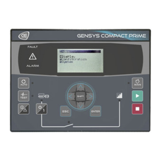
TECHNICAL DOCUMENTATION Front Face GENSYS COMPACT PRIME Buttons Functions SHIFT button Additional functions. RIGHT button Navigation button (Right). DOWN button Navigation button (Down). LEFT button Navigation button (Left). UP button Navigation button (Up). ENTER button Validating entry / MENU. ESC button Cancel entry / escape MENU. - Page 7 TECHNICAL DOCUMENTATION Buttons Functions Can only be used in MAN mode. Stop the Generator. STOP button Pressing once this button will set the Generator offload and initiate cooling down sequence. Can only be used in MAN mode. START button Start the Generator. MAN mode.
- Page 8 TECHNICAL DOCUMENTATION Button inhibition To inhibit front panel buttons, use the CRE Config Software/System/Button inhibition page. This page shows the list of front panel buttons, tick the corresponding box to inhibit actions on the button. Table below shows the 16 bits variable used for remote button inhibition by Modbus, each bit is assigned to a button: Variable Labe l...
-
Page 9: Rear Face
TECHNICAL DOCUMENTATION Rear Face GENSYS COMPACT PRIME Simplified Wiring Diagram A56_PRIME_90020-E-EN... -
Page 10: Panel Mounting
Unpack and keep the packaging in case of return. Make sure the unit does not show scratches or visible defaults. Otherwise describe them on the RMA sheet (available on CRE Technology website) and return it with the product to CRE Technology. A56_PRIME_90020-E-EN... - Page 11 TECHNICAL DOCUMENTATION Installation Preparation · Open type devices to be installed inside a suitable type rated enclosure. · Torque of mounting brackets: 0.4Nm. · Cut out the panel to 220x160mm (8.7x6.3in) minimum. · Make sure the cut-out is smooth and clean. Mounting A56_PRIME_90020-E-EN...
-
Page 12: Ul Requirements
TECHNICAL DOCUMENTATION UL Requirements ADV ANCED WIRING DIAGRAM Circuit separation The communication, sensor, and/or battery derived circuit conductors shall be separated and secured to maintain at least 1/4” (6mm) separation from the Generator and the Bus connected circuit conductors unless all conductors are rated 600V or greater. - Page 13 TECHNICAL DOCUMENTATION Mains Ratings Over-voltage Category III, 300VAC system voltage. Sensing Generator / Bus Voltage Measurement (J4) 300VAC max P-N, 2 phases; 500VAC P-P 3 phases, 35...75Hz. Current Inputs (J5) Must be connected through listed or recognized isolating current transformers with secondary rating of 5A max 50/60Hz.
- Page 14 External CT max ratio is 3250 (i.e. 3250:1 or, preferably, 16250:5). Bus current I1 Bus I1 On GENSYS COMPACT PRIME, this input must be used only for the earth fault protection. On GENSYS COMPACT MAINS and AMF COMPACT, if Mains power measurement is configured as 20mA, this input can be used as an earth current measurement.
- Page 15 TECHNICAL DOCUMENTATION Block and mark Description Note Input 1 Available input Shield Ground plane. Not availab le according to controller type. Block and Description Notes mark 7...38VDC Not protected against polarity reversal. Power 2.5mm² (AWG13). supply - Power 7…38VDC, consumed current: 130mA at 24V (standby and operation). supply + Shield Ground of the Generator.
- Page 16 CAN1: CRE- Isolated CAN bus, use twisted pair. Link® CAN L White wire with blue strip (when using a CRE Technology cable). CAN H Blue wire with white strip (when using a CRE Technology cable). Resistor - Strap to CAN H when inner resistor must be inserted (bus ends).
- Page 17 TECHNICAL DOCUMENTATION Installation Preparation · Open type devices to be installed inside a suitable type rated enclosure. · Torque of mounting brackets: 0.4Nm. · Cut out the panel to 220x160mm minimum (8.7x6.3in). · Make sure the cut-out is smooth and clean. Mounting A56_PRIME_90020-E-EN...
-
Page 18: Usage
TECHNICAL DOCUMENTATION Usage Password ADVICE USEFUL INFORMA TION § Adjustment tip § Using the module Failure to comply with these recommendations may cause the module to malfunction. The menus will be automatically locked if no operation is performed during the time set in the System menu (Factory setting: 5 minutes). -
Page 19: Lcd
TECHNICAL DOCUMENTATION Na vigation Press then and type in the level 1 password as described above to access the top level menu: A black pointer spots the currently selected item/setting. Three main menus are available on the LCD screen and in CRE Config Software: ·... - Page 20 TECHNICAL DOCUMENTATION To return to the previous page, press EVENTS Up to 15 active events and 30 archived events can be displayed on the screen. Each event is time-stamped as follows: jj/mm/yy hh:mn:ss protec. label On (or Off). To reset events, press Note: Correct the condition that triggered the protection before performing a reset;...
-
Page 21: Wiring
TECHNICAL DOCUMENTATION Wiring Tool: insulated screwdriver Ø2.5 mm (0.1 in), tightening torque: 0.8 Nm (7 lb-in) max. Accessories: 4, 5, 6, 8, 15 & 18-terminal cable connectors, protective gloves, carpet if the floor is wet. WARNING THE UNIT IS NOT PROTECTED ·... - Page 22 TECHNICAL DOCUMENTATION Connection diagrams These diagrams show that the PT (Potential Transformers) can be connected in various ways. · Star (wye) on Generator side (1 insulated high-voltage terminal per PT); the ratio is for example: · See on Bus side (2 insulated high-voltage terminals per PT); the ratio is for example: A56_PRIME_90020-E-EN...
- Page 23 (up to 0.5% full scale deviation). · External CT max ratio is 3250 (i.e. 3250:1 or, preferably, 16250:5). · On GENSYS COMPACT PRIME, this Bus current I1 Bus I1 input must be used only for the earth fault protection. ·...
- Page 24 TECHNICAL DOCUMENTATION Block and mark Description Note Optionally connected to CT –. For a 2-CT Generator common setup, see further. Analog inputs 0...500W. Common Connect it to battery -. Input 3 Available input Input 2 Available input Input 1 Available input Shield Ground plane.
- Page 25 TECHNICAL DOCUMENTATION Lower blocks WARNING RISK OF EQUIPMENT DAMAGE · As a protection against polarity reversal, install a 6A fuse between battery positive plug and terminal 8...35VDC +. · Connect battery negative to the module terminal 8...35VDC– with 2.5mm² (AWG13) cable. Failure to follow this instruction can damage the controller.
- Page 26 AVR output – Common if shielded. CAN1 : CRE-Link® Isolated CAN© bus, use twisted pair. White wire with blue strip (when using a CRE Technology CAN L cable). Blue wire with white strip (when using a CRE Technology CAN H cable).
-
Page 27: Digital Inputs
TECHNICAL DOCUMENTATION Digital Inputs ADVICE USEFUL INFORMA TION § Adjustment tip § Using the module Failure to comply with these recommendations may cause the module to malfunction. Note: If a digital input changes a piece of data also to be written by Modbus, the latest request takes over the other. - Page 28 TECHNICAL DOCUMENTATION Dela ys For each input, two delays can be defined in 100ms steps between 0 and 6553s: Functions Each input can be configured using CRE Config Software. Function list is available in Software variables. A56_PRIME_90020-E-EN...
-
Page 29: Digital Outputs
TECHNICAL DOCUMENTATION Digital Outputs Each output is tagged with a label defined in CRE Config Software/Configuration, and features several attributes set in the Configuration menu: · Direction · Pulse length: 0 means no pulse · Function Direction Each output can be: ·... -
Page 30: Analog Inputs
TECHNICAL DOCUMENTATION Analog Inputs In addition to the speed and electrical currents and voltages, three analog inputs are available. They measure a resistance 0…500Ω . However, they can serve as digital inputs or 20 mA transducer input. Input Each input is tagged with a name and preset to a function. It features several attributes preset in CRE Config Software/Configuration/Inputs/Analog inputs: ·... - Page 31 TECHNICAL DOCUMENTATION Note: Other references are available in CRE Config Software. Protections The input threshold features several attributes preset in CRE Config Software/Configuration/Protections/Engine/battery protections/Analog inputs protection: · Level (LV): limit value in units; it can be a low or high threshold. ·...
- Page 32 TECHNICAL DOCUMENTATION A-1 : Analog Sensor 2 Wires A-2 : Analog Sensor 1 Wire B-1 : Digital Sensor 2 Wires A56_PRIME_90020-E-EN...
- Page 33 TECHNICAL DOCUMENTATION B-2 : Digital Sensor 1 Wire WARNING The warranty will be void if the manufacturer's instructions are not respected. A56_PRIME_90020-E-EN...
-
Page 34: Settings
TECHNICAL DOCUMENTATION Set tings Engine Internal start sequence During the start sequence, the module controls the prelub, preglow, crank and fuel outputs when proper conditions are met, whereas the protections are inhibited. This concerns all engine protections. Main start phases: The engine is considered to have started when the speed reaches the crank drop out. - Page 35 TECHNICAL DOCUMENTATION Chronogram for Gas Engine Conditions before start-up Module monitors the oil pressure and water temperature: 1. Oil pre-lubrication check: The oil pressure must be OVER the threshold [3473]. 2. Water temperature check: The water temperature must be UNDER the threshold [3474]. Setting thresholds to 0 prevent the module to check those conditions before start-up.
- Page 36 TECHNICAL DOCUMENTATION Starter With multiple starters, preset digital outputs to Crank2 and Crank3. The Starter number depends on the preset output number. The starters are attempted according to the starter numbers as far as the engine fails to start. Setting Label Description By default...
- Page 37 TECHNICAL DOCUMENTATION External automatic start MODULE Some engines are equipped with an ASM (Automatic Start Module). On start (AUTO/TEST/MAN mode), the module empowers it to energize the crank and fuel and to synthesize the engine events. The setup depends on the type of ASM: Step Presetting Connections to ASM...
-
Page 38: Circuit Breakers
TECHNICAL DOCUMENTATION Circuit Breakers Circuit breaker operating modes Two logic outputs (relay or transistor) are used to control the circuit breakers - 1 for opening and 2 for closing. These outputs allow different types of circuit-breakers to be controlled. The settings are accessible from CRE Config Software/Configuration/Outputs/GeneratorBreaker. ADVICE USEFUL INFORMA TION §... - Page 39 TECHNICAL DOCUMENTATION Circuit breaker control mode Value Mode Circuit breaker chronogram 1: Continuous contact to open. 2: Positive pulse to close. 1: Continuous contact to open. 2: Continuous contact to close. 1: Under-voltage (MN) coil opening. 2: Pulse to close. 1: Under-voltage coil opening.
- Page 40 TECHNICAL DOCUMENTATION Pulse configuration The settings can be accessed from CRE Config Software. Positive Pulse Configuration/Outputs/Generator Breaker. For the positive pulse control of the Generator breaker, set the parameter [2301]. Coil Control Configuration/Outputs/Generator Breaker. For fail-safe control, set parameters [2302], [2303] for the Generator breaker To detect the position of the circuit breaker, a logic input must be configured as: Function Value...
- Page 41 TECHNICAL DOCUMENTATION Configuration of circuit breaker commands Two logic outputs (relay or transistor) must be configured as described in the table below and connected to the circuit breaker. Function Description Close circuit breaker control Closing the circuit breaker (continuous, pulse, MNcoil). Open circuit breaker control Opening the circuit breaker (continuous, pulse, MNcoil).
-
Page 42: Speed/Voltage Control
Generator. The appendix Analog speed regulation gives the parameters to be set for several controller models. To use the module with other models, adjust the amplitude and offset according to the manufacturer's documentation and/or contact CRE Technology technical support. A56_PRIME_90020-E-EN... - Page 43 AVR models. To use the module with other models, adjust the amplitude and offset according to the manufacturer's documentation and/or contact CRE Technology service. Speed/Voltage controlled by Contacts/Pulses When digital outputs are connected to the speed governor and/or AVR, the PID controllers increment/decrement speed/voltage by changing the state of these outputs: A digital potentiometer converting pulses into analog values can be used.
- Page 44 TECHNICAL DOCUMENTATION A pulse is generated when the absolute value of the correction applied exceeds the dead band. The larger the correction signal ([4405] for speed and [4411] for voltage), the longer the pulses are and the shorter the time between each pulse is.
-
Page 45: Synchronization
TECHNICAL DOCUMENTATION Synchronization Functioning The module launches the synchronization only if the Busbar provides at least 80% of the nominal voltage. It manages a correction on frequency and voltage to go and stay on the acceptance windows (can be handled in Synchronization). - Page 46 TECHNICAL DOCUMENTATION The PID parameters can be set using CRE Config Software/Configuration/Control Loop. Adjustment procedure DANGER RISK OF ELECTRIC SHOCK, EXPLOSION OR ARCING § The module may only be installed and maintained by qualified electricians. § Use personal protective equipment (PPE) §...
- Page 47 TECHNICAL DOCUMENTATION Control on dead bus management In case of an emergency start of the Power plant (no voltage on the common Bus-bar), the units communicate through CRE-Link® to elect a module which will close first its circuit breaker on the Bus-bar: it is the arbitration procedure, to avoid closing 2 circuit breakers at the same time, when the generators are not synchronized.
-
Page 48: Load/Unload Ramp
TECHNICAL DOCUMENTATION Load/Unload Ramp Functioning After a synchronization, the module ramps up the Generator load (soft transfer) to avoid overload or a load impact (hard transfer). The module calculates the average of the active power read from the CRE-Link® CAN bus. It then starts a load ramp to progressively reach this value (KW regulation). -
Page 49: Regulation Kw/Kvar
TECHNICAL DOCUMENTATION Regulation KW/KVAR Functioning The module switches to the regulation mode on KW and on KVAR around its set-point after a load ramp. The module calculates the active and reactive power it should supply using the information received from the CRE-Link®. - Page 50 TECHNICAL DOCUMENTATION this oscillation may affect the load sharing. Keep in mind that an instability on the speed governor or the AVR system cannot be corrected by PID on the module. A56_PRIME_90020-E-EN...
-
Page 51: Protections
TECHNICAL DOCUMENTATION Protections Functioning The protections are triggered by an internal or external event (alarms, faults, logic inputs, CAN bus loss, etc.). In order to protect the process, engine or alternator, an action must be associated with the events. These actions are of different kinds: ·... - Page 52 TECHNICAL DOCUMENTATION Value Type Action Description paralleling is disabled but the dynamic paralleling remains active. The static paralleling is disabled but the dynamic Backup No start if static paralleling paralleling remains active. These actions have to be configured with CRE Config Software. List of potential alarms/faults can be downloaded via CRE Config Software/System/PC transmit/receive: List of actions on alarms-faults.
- Page 53 TECHNICAL DOCUMENTATION Generator electrical fault Generator breaker position Generator status with respect to coupling Count of re-synchr. launches Audible or visual w arning device To trigger an external alarm when a protection trips, connect the alarm to a logic output configured as a "Horn". The signal duration is configurable by [2478] (0 means that the alarm will be activated until manual shutdown);...
-
Page 54: Control Loop Pid
TECHNICAL DOCUMENTATION Control Loop PID eMPIRICAL PID GAIN TUNING 1. Set all the gains to 0 (except G gain). 2. Increase the P gain until you have a stable oscillation. 3. Increase the D gain until the oscillation is canceled. 4. -
Page 55: Advanced Settings
TECHNICAL DOCUMENTATION Advanced Set tings Droop Functioning In order to maintain load sharing, the droop is used in the case of the following CRE-Linkâ problems: · Isolated product (if [3052] is set to 8 or 9). · Missing product (if [3054] is set to 8 or 9). ·... -
Page 56: Load Dependent Start/Stop
TECHNICAL DOCUMENTATION Load Dependent Start/Stop Functioning This function allows to automatically start and stop Generators of a Power plant according to the load variation. This prevents overload (you are advised to run generators between 70 and 85%). CRE-Linkâ makes it possible to share load information and coordinate the actions. - Page 57 TECHNICAL DOCUMENTATION Example A 4x100KW Power plant with a load that increases linearly from 0 to 400KW, then decreases to 0KW. Start threshold [2854] is set to 80% and the stop threshold [2857] is set to 20%. Generator #1 is permanently running. When load increases above the start threshold, Generator #2 starts to supplement Generator #1, then Generator #3 and Generator #4 start.
- Page 58 TECHNICAL DOCUMENTATION Start-stop by Running Hours If this way is selected, the Generator to start/stop is auto selected according to the module running hour meter: · On increasing load demand, the next Generator to start is the one with fewest running hours. ·...
-
Page 59: Static Paralleling
TECHNICAL DOCUMENTATION Static Paralleling Cases STUDY · Starting a full plant with multiple generators in an emergency on dead bus: the generators are ready to take load in the shortest possible time, without warm-up. Bottom line: full plant availability in less than 10s typically. This meets the NEC700 requirements. ·... - Page 60 TECHNICAL DOCUMENTATION Sequence The generators are synchronized through CRE-Link®: 1. All remote start are activating at the same time. 2. All the module units close their breaker and start their engine. 3. The remanent voltage appears. 4. The fastest Generatorʼs speed reaches [2053]. 5.
-
Page 61: Load Shedding
TECHNICAL DOCUMENTATION Load Shedding Functioning The load shedding is the ability to disconnect less important consumers if the Power plant is overloaded even when the full capacity is engaged; this prevents a blackout. Any module – generally one – in the Power plant can take care of excessive demand. If the KW demand exceeds the Power plant capacity and/or the frequency has dropped below a threshold for a given time, the dedicated module activates outputs to shed non-essential loads. - Page 62 TECHNICAL DOCUMENTATION The charts show the trip alarm and trip outputs depending on the Generator load or frequency: The trip counter sums the times during which at least one consumer is shed. It is reset at the same time as the alarm: A56_PRIME_90020-E-EN...
-
Page 63: Maintenance Schedule
TECHNICAL DOCUMENTATION Maintenance Schedule The configuration of the maintenance schedule is carried out from the CRE Config Software. The consultation is done in Display/Maintenance ("off" means that the servicing cycle is not defined). When a cycle has elapsed, an alarm is displayed and the module's alarm LED flashes. In the module alarm page you can view the expired cycle. -
Page 64: Power Plant Application
TECHNICAL DOCUMENTATION Power Plant Application Load Sharing General information The module is informed of the load measurements of the other Generators via CRE-Link®. They distribute the load in proportion to their rated power. This distribution method is more reliable and accurate than an analog solution. Speed control is used to distribute the active load. - Page 65 TECHNICAL DOCUMENTATION Operating mode 1. Press : the associated LED lights up. 2. Press : the module starts the Generator. 3. Press to move the Generator to the load. Depending on the configuration, the sequence may vary: · synchronization (if a voltage on the Bus-bar is present). ·...
- Page 66 TECHNICAL DOCUMENTATION Local key Substitution function Manual start / manual stop Entry + speed/ Entry - fast OR Entry +U/ Entry -U AUTO AUTO mode requires the use of a logic input configured as Remote start. Until the digital input is activated and the delay has expired, the AUTO mode is not active. If the input is deactivated, the module is considered unavailable during Start/stop depending on load management.
-
Page 67: Advanced Functions
TECHNICAL DOCUMENTATION Advanced Functions Scheduler Presentation The Scheduler can activate any function that can be controlled by logic input. These functions can be activated once or repeatedly. Functioning The Scheduler is presented in table form. Each row in this table corresponds to an event. There are 2 types of events One-time Event 1. - Page 68 TECHNICAL DOCUMENTATION Monthly 1. Function active during the event. 2. The event is repeated. 3. The event will be repeated every month (or every X month according to the parameter "every"). 4. Day of the month on which the event will take effect. 5.
-
Page 69: Alternative Selections
TECHNICAL DOCUMENTATION Alternative Selections Presentation The Alternative selections function allows one or more parameters to be switched between two values via a digital input. Functioning This function can be set using the CRE Config Software/Configuration/Alternative selections. Each line is composed as follows: 1. - Page 70 TECHNICAL DOCUMENTATION Example Page Configuration/Alternative selections: Page Configuration/Digital inputs: In the example above, digital input 1 allows you to modify the PT ratio and the Nominal Frequency parameters, and digital input 2 allows you to modify the Under frequency threshold parameter: ·...
-
Page 71: Easy Flex
TECHNICAL DOCUMENTATION Easy Flex® Presentation Easy Flex® offers a simple and innovative way of programming, allowing you to adapt the controller to your needs. Functioning Easy Flex® is presented in the form of a table. Each line of this table corresponds to an operation between 2 values. - Page 72 TECHNICAL DOCUMENTATION Search Engine To select a variable, click on the orange box to display the search engine. The Filter button allows you to quickly find the desired parameter. User v ariables To allow intermediate result storage, "User variables" are available. These variables can be used to: ·...
-
Page 73: Modbus Tcp Mapping
TECHNICAL DOCUMENTATION Modbus TCP Mapping Configurable block To create your own blocks, use the variables [10000]…[10299] in CRE Config Software/Configuration/Modbus redirection. There are two ways to configure these blocks: 1. Configuration in CRE Config Software/Configuration/Modbus redirection: enter the codes of the variables to read;... -
Page 74: Logger
TECHNICAL DOCUMENTATION Logger The Logger tool is used to track value or status changes up to 10 variables at the user's choice. Power status and engine mode variables are always recorded as long as the logger is not set to Off. This function is available in CRE Config Software/Configuration/Logger. -
Page 75: Communications
TECHNICAL DOCUMENTATION Communications Network Setting up your PC connection Materials required: · A CAT 5 cross Ethernet cable (marked CROSSOVER CABLE along its sheath) for direct connection to the module from your computer. · The CAT 5 straight Ethernet cable (marked PATCH CABLE or STRAIGHT-THROUGH CABLE along its sheath) can only be used with an Ethernet switch. - Page 76 TECHNICAL DOCUMENTATION Click on Properties (Windows 7 or 8 or 10). Change the IP address of the MODULE Using CRE Config Software (or LCD display), in the System/Network Configuration menu. The module supports DHCP: in this case, the module must be connected to a network equipped with a DHCP server.
-
Page 77: Modbus Tcp/Ip
TECHNICAL DOCUMENTATION Modbus TCP/IP Abilities The complete list of variables is described in Software variables. Through Ethernet communication where the module acts as a Modbus slave, you can: · Upload many readings and module internal variables. · Download values for many module internal variables. Type Range Fault access right... - Page 78 TECHNICAL DOCUMENTATION Access rights The access rights depend on the parameter type and on Modbus access permissions. To manage access rights, set to 1 the corresponding bits in the word [3015]: Description Bit # Default value Writing to date/ time Writing to Engine counters Not used Writing to digital input function register...
- Page 79 TECHNICAL DOCUMENTATION Modbus communication example The table below shows a Modbus TCP client sending a reading request (function 04) of 6 registers starting from variable [0079]. Client request Module server response Value Field Field Value Function code Required function. Starting Register (MSB) Data bytes (=2*Nb of registers requested).
-
Page 80: Cre-Link
CAN bus ALARMS/faultS CAN communication between CRE Technology units is continuously checked by each unit on the CAN bus. The count of units connected to CAN bus must be the same as the count of units declared inside each unit. In case of a problem on the bus, alarms or faults can occur: ·... -
Page 81: Canopen
TECHNICAL DOCUMENTATION CANopen CANopen extension modules can be used to increase the number of digital inputs and outputs of the module. Overall max. count of added inputs/outputs: 32 I and 32 O. They are read/written every 100ms. Configuration Setting Label Value Description [3151]... -
Page 82: Sae J1939
The module can communicate with a large number of J1939 engines. As the engine list accrues, please contact CRE Technology or your local distributor if your engine is not mentioned in this document. In any case, if your ECU does not belong to the following list, try: 1. - Page 83 TECHNICAL DOCUMENTATION Fuel circuit and ECU SPN Description 91 Accelerator pedal position 1 (run in %). F003 1242 Instantaneous estimated brake power. FE92 512 Driver's demand engine - Percent torque related to maximum engine torque. F004 515 Engine's desired operating speed. Indication of optimal speed for the current conditions. May include the torque generated to accommodate power demands and exclude dynamic commands from smoke/shift.
- Page 84 TECHNICAL DOCUMENTATION 108 Barometric pressure. FEF5 1387 Pressure auxiliary sensor #1 1388 Pressure auxiliary sensor #2 247 Engine total hours of operation. FEE5 A56_PRIME_90020-E-EN...
- Page 85 TECHNICAL DOCUMENTATION Air, exhaust and alternator SPN Description 107 Air inlet filter #1 differential pressure (first or sole filter). FEF6 52 Inter-cooler temperature. 106 Air inlet pressure (at inlet to intake manifold or air box). FEF6 102 Intake manifold #1 pressure (boost pressure measured downstream of turbo compressor). FEF6 3563 Intake manifold #1 absolute pressure.
- Page 86 TECHNICAL DOCUMENTATION 1125 Alternator winding 2 temperature. FEA7 1126 Alternator winding 3 temperature. FEA7 Oil and coolant circuits SPN Description 98 Oil level (ratio of sump current volume to required volume). FEEF 99 Oil filter differential pressure. 100 Oil pressure. FEEF 175 Oil temperature 1.
- Page 87 TECHNICAL DOCUMENTATION faults The module can monitor diagnostic messages (DM1) from the ECU. Only relevant diagnostic messages are taken into account and used in the module fault/alarm system. The module can understand and interpret messages for display, process, and protection. When you activate the internal module RESET ([SHIFT+INFO] button or remote reset), the module sends a reset message (DM3) to the ECU.
- Page 88 TECHNICAL DOCUMENTATION Controls Description Details Requested speed Engine speed which the engine is expected to operate at if the speed control mode is active. Start-Stop Engine shutdown switch. Frequency selection Ability to switch the rated speed. Switched on a state transition while engine speed is 0. 50/60Hz (CM570 and PGI) or sources given through a nibble (e.g.
-
Page 89: Can Bus Good Practices
TECHNICAL DOCUMENTATION CAN bus Good Practices This chapter describes rules to be used to ensure reliable CAN communication. These rules must be applied to all CAN communications, including CRE-Link® and ECU/remote I/O CAN bus. In an EMI environment, use a shielded cable to connect CAN bus. The table below lists the DB9 CAN standard wiring: Terminal Standard CAN... - Page 90 The following table shows the maximal length of a CAN bus depending on the bit rate: Bit rate (Kbits/s) Maximal length (m) 5000 2500 1000 The next table lists the standard bit rate of each CAN protocol that can be used by a CRE Technology unit: Bit rate Protocol Note (Kbits/s) CAN1 CRE-Link®...
-
Page 91: Website
TECHNICAL DOCUMENTATION Website Access Menu trees During navigation on the PC, press the ESC button to return to the parent menu of the page displayed in the browser. Access to the website 1. Connect a PC to the module via an Ethernet connector. 2. -
Page 92: File Transfer
These files can be transferred from or to the module. For this, use CRE Config Software or the embedded website. Note: CRE Technology strongly recommend using CRE Config Software to edit module settings to prevent any kind of error with manual editing in the configuration file. - Page 93 TECHNICAL DOCUMENTATION Example: S/N:0114A0001 Type:A56Z0 Version:v1.00 Bootversion:v1.00 Date:28/06/15 Hour:12h25m21s ***** Alarm/fault effect ***** 0 : Desactive 1 : Defaut Gen electrique 2 : Defaut Bus electrique 3 : Alarme 4 : Defaut non critique 5 : Defaut critique 6 : Help+Defaut non crit 7 : Help+Defaut Gen.Elec 8 : Statisme Potentiel Alarm./Def.
-
Page 94: Firmware Update
TECHNICAL DOCUMENTATION Firmw are Update Prerequisites 1. Upgrading software is done via an Ethernet connection. It is mandatory to have a PC connected to the module (Use an Ethernet cable from module to PC without using LAN). 2. Stop the Generator (The module must be in the Waiting power state). 3. -
Page 95: Appendices
TECHNICAL DOCUMENTATION Appendices Analog Voltage Regulation (AVR) Model Amplitude Offset AVR output AVR common Note AVR COMMON terminals 7 & 9/10. BASLER ELECTRIC Model Amplitude Offset AVR output AVR common Note Remove the shunt AEC 63-7 between AVC 63-4(A) terminals 6 & 7 of the AVR. - Page 96 TECHNICAL DOCUMENTATION CATERP ILLAR Model Amplitude Offset AVR output AVR common Note DVR KVAR/PF 1.0V CDVR 4.5V P12.3 P12.6 CUMMIN S Model Amplitude Offset AVR output AVR common Note Cosimat N 4.5V 4.5V MA329 A2(+) A1(-) Model Amplitude Offset AVR output AVR common Note K65-12B...
- Page 97 TECHNICAL DOCUMENTATION LEROY SOMER Model Amplitude Offset AVR output AVR common Note D510 Depending on the configuration (0-10V or +/-10V) R230/438/448/44 Pot input – 1.0V Pot input + Delete the shunt R610 3F 4.5V MAGN ELLI MOTORI Model Amplitude Offset AVR output AVR common Note...
- Page 98 TECHNICAL DOCUMENTATION MECC ALTE SPA Model Amplitude Offset AVR output AVR common Note –4.5V Pot – UVR6 2.0V Pot + SIN CRO Model Amplitude Offset AVR output AVR common Note AVR potentiometer V fully EXTPOT+ EXTPOT– counterclockwise. Delete shunt. STAMFORD Model Amplitude Offset...
-
Page 99: Ecu J1939
TECHNICAL DOCUMENTATION ECU J1939 CATERP ILLAR Manufacturer ECU [3101] Air + Exhaust + Alternator Oil and coolant [3100] GENERIC [0] A4E2 (C4.4 C6.6)[1] 91 515 250 157 183 168 158 247 102 105 106 172 92 513 ECU [3101] Speed Start/Stop Speed selection GENERIC [0]... - Page 100 TECHNICAL DOCUMENTATION Cummins 109G ECU may not support J1939 speed control. ECU with Cummins G Drive firmware should support J1939 speed control. ECU [3101] Speed Start/Stop Speed selection GENERIC [0] QSX15-G8 (CMS570) [1] CM850 [2] QSB5 (PGI 1.1) [3] QSB7 (PGI 1.1) [4] QSL9 (PGI 1.1) [5] QSM11 (PGI 1.1) [6] QSX15 (CMS570) [7]...
- Page 101 TECHNICAL DOCUMENTATION DEUTZ FAHR Manufacturer Air + Exhaust + ECU [3101] Fuel & ECU Oil and coolant [3100] Alternator GENERIC [0] EMR [1] 91 512 188 183 247 102 92 513 100 110 91 512 183-4-8 174 158 108 EMR2 [2] 102 105 92 513 98 100 110 111 91 512 2432 183 174 94...
- Page 102 TECHNICAL DOCUMENTATION J OHN DEERE Manufacturer Air + Exhaust + ECU [3101] Fuel & ECU Oil and coolant [3100] Alternator GENERIC [0] 91 512 515 2432 52 106 102 105 101 98 100 175 JDEC [1] 182 250 183 184 94 157 173 176 81 92 513 109 110 111 112 174 158 247...
- Page 103 TECHNICAL DOCUMENTATION ADEC The SAM (Service and Automation module) is associated with the ADEC 2000 or ADEC 4000. The set is referred to as the ECU7. Disconnect X13 to turn off the power. Insert the CCB2 card into SAM slot #3. The ADEC ECU, SAM and the module communicate via 2 CAN buses: a CAN bus between the SAM and the ADEC with a proprietary protocol, a CAN bus between the module and the SAM with the J1939 protocol.
- Page 104 TECHNICAL DOCUMENTATION ECU8 Smart Connect is used for: · select the origin of the speed control via an 8 position selector · set droop frequency and slope Via the K1 connection box, the ECU8, the Smart Connect and the module are connected: a CAN bus between the Smart Connect and the ECU8 with a proprietary protocol, a CAN bus between the Smart Connect and the module with the J1939 protocol.
- Page 105 TECHNICAL DOCUMENTATION A56_PRIME_90020-E-EN...
- Page 106 TECHNICAL DOCUMENTATION P ERKIN S Manufacturer Air + Exhaust + ECU [3101] Fuel & ECU Oil and coolant [3100] Alternator GENERIC [0] 91 515 188 174 250 183 1100 A4E 102 105 92 513 100 110 ECU [3101] Speed Start/Stop Speed change GENERIC [0] 1100 (A4E)
- Page 107 TECHNICAL DOCUMENTATION VOLVO P EN TA Manufacture Air + Exhaust + ECU [3101] Fuel & ECU Oil and coolant r [3100] Alternator GENERIC [0] EMS2 [1] 94 182 250 247 102 172 100 175 110 Same as Deutz EDC4 [2] Same as Deutz EMR2 Same as Deutz EMR2 EMR2...
-
Page 108: Analog Speed Regulation
TECHNICAL DOCUMENTATION Analog Speed Regulation BARBER COLMAN Model Amplitude Offset Speed output Speed common Note With analog input 0.5V ILS input 0.5V ILS signal ILS+2.5V The parameters Digital Amplitude and DPG 2201 ILS signal supply(+5V) offset depend on the connection ILS signal BAT- A56_PRIME_90020-E-EN... - Page 109 TECHNICAL DOCUMENTATION CUMMIN S Model Amplitude Offset Speed output Speed common Note ECM for QSK23 / QSK40 / QSK45 / 2.5V 06 (5V) QSX15 / QSK 60 See diagram 1.5V below ECM (QST30) 15 (7,75V) Barb er Colman frequency b ias input. The very high sensitivity of the Cummins EFC model, requires connecting it to the module as shown below.
- Page 110 TECHNICAL DOCUMENTATION DEUTZ FAHR Model Amplitude Offset Speed output Speed common Note +/- 1.5 Hz not to reach the 2.5V overspeed of the HEIN ZMAN N Model Amplitude Offset Speed output Speed common Note KG6 / System E6 2.5V 2.5V PANDAROS DC6 2.5V A56_PRIME_90020-E-EN...
- Page 111 TECHNICAL DOCUMENTATION J OHN DEERE Model Amplitude Offset Speed output Speed common Note 2.5V 2 differents wiring JDEC for the same controller LEVEL III (ref. speed) 999. Model Amplitude Offset Speed output Speed common Note MDEC 36 & 7 (5V) P ERKIN S Model Amplitude...
- Page 112 TECHNICAL DOCUMENTATION WOODW ARD Speed output Speed common Model Amplitude Offset Note - 2301A/D Shunt 14-16 ILS+speed Shunt 26 (com) - (Without U&I) on 0V 2301D 2301A Speed 16 connected on 4.5V 2.5V only Remove shunt EPG System between P/N 8290-189 2.5V 11 (0.6V) Terminal 11 and...
-
Page 113: Short Circuit Protection
TECHNICAL DOCUMENTATION Short Circuit Protection The tripping time depends on the duration an alternator winding can endure an over current. A IDMT (Inverse Definite Minimum Time) curve is defined by: · a type (IEEE, IEC, IAC), · Is: current for infinite time in type 1 (asymptote value); type 1.2 is not used, ·... - Page 114 TECHNICAL DOCUMENTATION T curves with t=1 for I/Is=10: A56_PRIME_90020-E-EN...
- Page 115 TECHNICAL DOCUMENTATION A56_PRIME_90020-E-EN...
- Page 116 TECHNICAL DOCUMENTATION Inverse curves just above the pick-up value (not logarithmic abscissae I/Is) for various value of TMS: A56_PRIME_90020-E-EN...
- Page 117 TECHNICAL DOCUMENTATION A56_PRIME_90020-E-EN...
- Page 118 TECHNICAL DOCUMENTATION IEEE CURVES Characteristic curve Moderately inverse 0.515 0.1140 0.02 Very inverse 19.61 0.491 Extremely inverse 28.2 0.1217 A56_PRIME_90020-E-EN...
- Page 119 TECHNICAL DOCUMENTATION HOW TO DERIVE A CURVE BY PARALLELISM Say a curve is known. We know tsA (s stands for the start curve) for IA/Is (s stands for set point). Two curves with same k, a and c are parallel: K= tsA/Ts10 = tA/T. This can be used to find tA. In the preceding curves in logarithmic plot, Ts10=1.
- Page 120 TECHNICAL DOCUMENTATION VIT, LTI IEEE MI IEEE VI IEEE EI I/Is SIT IEC/A IEC/B IEC/C IEC/D IEC/E IEC/F not av. Means only valid for IEC curves A56_PRIME_90020-E-EN...
-
Page 121: Troubleshooting
TECHNICAL DOCUMENTATION Troubleshooting To get a history of alarms-faults, stop the Generator, connect to CRE Config Software/System/PC transmit/receive/Download log file from module, and click Download. To restore factory settings into CRE Config Software, navigate to CRE Config Software/System/PC transmit/receive/Reset factory settings, and click Reset. Message "Sensor lost"... - Page 122 TECHNICAL DOCUMENTATION Error Messages When Transferring a File to the Module Note: "…" indicate a variable number, a label number or a text number according the error message. It will help you to locate your error in your configuration file. ERROR 001: Only when GENSET is STOP File transfer between computer and the unit should be done only when all conditions below are met i.e.
- Page 123 TECHNICAL DOCUMENTATION The language file version is above the module version. Upgrade your module with the latest version available or catch the language file compatible with your module version. ERROR 023: Label …. does not exist. Modifying this label is not allowed. Check the label number before sending the configuration file again. ERROR 024: Unit ….
- Page 124 TECHNICAL DOCUMENTATION Warning Warnings do not prevent the module to work but inform the user of a potential problem in its configuration file. WARNING 001: Wrong size of label …. WARNING 002: Wrong character entered in label …. WARNING 003: Wrong size of text …. WARNING 004: Wrong character entered in text ….
-
Page 125: Standards For Generator
TECHNICAL DOCUMENTATION Standards for Generator ISO 8528-1 CLASSES AND POWER DESIGNATIONS Various load-duration profiles are defined. Here is the correspondence between classes and powers: Power Conditions Conditions Controller designation designation Allowable average power output Prime Running Overload: max: 1 h GENSYS PRIME over a 24-hour period is 70% of... -
Page 126: Certifications
TECHNICAL DOCUMENTATION Certifications DECLARATION OF CONFORMITY A56_PRIME_90020-E-EN... - Page 127 TECHNICAL DOCUMENTATION ISO CERTIFICATe - 2015 A56_PRIME_90020-E-EN...
- Page 128 TECHNICAL DOCUMENTATION Download the certification A56_PRIME_90020-E-EN...
-
Page 129: Software Variables
TECHNICAL DOCUMENTATION Sof tw are Variables A56_PRIME_90020-E-EN... - Page 130 List of variables General Power plant ..........139 Number of generator (2000) .
- Page 131 AVR control ..........147 AVR signal output inversion (2254) .
- Page 132 Control on very high coolant temperature (3107) ....154 Control on low oil pressure (3108) ......154 Control on very low oil pressure (3109) .
- Page 133 Reverse kW/kVar ......... 164 Reverse kW .
- Page 134 Voltage unbalance ........174 Threshold (2486) .
- Page 135 Timer (2363) ........183 Validation (2364) .
- Page 136 Timer Min Max Speed output (2389) ......195 Control Min Max Speed output (2390) ..... . . 196 Max/Min AVR output protection .
- Page 137 Undervoltage coil security timer GCB (2303) ....202 CANopen CANopen ..........202 CANopen .
- Page 138 Proportional Gain for KW (2909) ......209 Integral Gain for KW (2910) ......209 Derivate Gain for KW (2911) .
- Page 139 Configuration General Power plant Variable Number of generator (2000) Unit Init Description Number of generator on the power plant. This parameter is used for the CAN communication between products. Variable My number (2001) Unit Init Description Generator number. This parameter is the ID of the product used for the CAN communication between products.
- Page 140 Variable Voltage system (2003) Unit Init Description This setpoint is used to select the alternator voltage architecture. 3 setpoints can be used : - Single phase (value 0) : Connection of 1 active phase wiring and 1 neutral wiring for generator and for Mains.
- Page 141 Mode Variable Power up in mode (2012) Unit Init Description This setpoint is used to select the mode of the product when the power supply is applied. 3 setpoints can be used : - Manual (Value 0) : The product will switch-on on Manual mode - Test (Value 1) : The product will switch-on on Test mode - Auto (Value 2) : The product will switch-on on Auto mode Variable...
- Page 142 Variable Base load kW setpoint (2107) Unit 32 500 Init Description This setpoint adjusts the kW level for the base load operation : kW level reach for the generator power during the Mains paralleling operation. Power management system Load dependant start/stop Load dependant start/stop Variable Load/unload mode (2850)
- Page 143 Variable Custom number (2863) Unit Init Description Number used for load/unload by custom configuration Variable Hour (2865) Unit 1000 Init Description Hour used for load/unload with balance engine hours Load shedding Load shedding Variable Under frequency validation (3702) Unit Init Description Enables/Disables underfrequency monitoring for non-essential load shedding Variable...
- Page 144 Variable Maximum load threshold 2 (3704) Unit 200 0 Init 1000 Description Second overload level (must be higher than level 1) Variable Timer 1 for threshold 1 (3706) Unit 999 9 Init Description Delay before first level activation (kW and Hz) Variable Timer 2 for threshold 2 (3707) Unit...
- Page 145 Variable Nominal kVAR reactive power (2106) Unit kVAR 32 500 Init Description This setpoint adjusts the kVAR nominal power of the generator. All the electrical protections for kVAR on %, load sharing calculation or power management with the mains will be calculated around this nominal value.
- Page 146 Variable High kW active power threshold (2867) Unit 100 0 Init Description This setpoint adjusts the kW high limit treshold on generator in case of mains paralleling. The generator will never exceed this kW during Mains paralleling operation. Basically, this limit will be calculated at around 90 - 100 % of the generator nominal kW. Variable Load ramp timer (2853) Unit...
- Page 147 AVR control Variable AVR signal output inversion (2254) Unit Init Description This setpoint adjusts the ”AVR signal output inversion”. For most of AVR brand connection : - The module increase the AVR output signal to increase the alternator voltage (Voltage external setpoint).
- Page 148 Variable Pulse Divider (3653) Unit Init Description This setpoint adjusts the ”pulse divider” in case of voltage control by pulses. This pulse divider is able to change the response time of voltage control by pulses. If you increase the value of pulse divider, you will decrease the time of pulse active. Variable PT ratio (2150) Unit...
- Page 149 Variable Warm up selection (3479) Unit Init Description When starting the engin,choice to select the warm up speed (0 = Nominal speed / 1 = Idle speed) . Variable Engine type (3477) Unit Init Description Engine type (0 = Diesel / 1 = Gas). Crank settings Variable Maximum starting attempts by starter (3461)
- Page 150 Check before start Variable Preheating coolant temperature threshold (3474) Unit 3276 7 3276 7 Init Description Minimum Preheating coolant temperature threshold before engine start. (0 = no check) Variable Minimum oil prelubrication threshold (3473) Unit mBar 6553 5 Init Description Minimum oil prelubrification threshold before engine start.
- Page 151 Control settings Speed common settings Variable Speed sensor type (2200) Unit Init Description Type of speed measurement for the engine (0=pick-up/1= alternator/2=J1939) Variable Number of poles pair (2202) Unit Init Description pole pair number of your alternator. It will be used to measure the speed of your engine. Variable Number of teeth for pick-up (2201) Unit...
- Page 152 Variable Amplitude (2205) Unit 0 00 10 00 Init 1000 Description ESG gain (speed output ). Variable Offset (2206) Unit 10 00 10 00 Init Description ESG offset (speed output ). When the engine is at nominal speed, the offset need to be parameter to have 50Hz or 60Hz (It depends on your electrical installation).
- Page 153 Water temperature control Variable Coolant temperature switch (3451) Unit Init Description Water temperature selection. You can read the water temperature with the analog input 1,2,3 or you can read the water temperature with the J1939 if you use it. (0= Analog 1 // 1=Analog 2 // 2=Analog 3 // 3=J1939) J1939 J1939 engine selection...
- Page 154 Variable Control on very high speed (3105) Unit Init Description Put an alarm or a fault. If your engine is in overspeed, the alarm or the fault will be activated. You can choose what do you need in the drop-down list. (alarm level 2) - Unused : no action. - Generator electrical fault : The protection opens the generator breaker and tries to re- synchronize again.
- Page 155 Variable Control on low oil pressure (3108) Unit Init Description Put an alarm or a fault. If your engine have a low oil pressure, the alarm or the fault will be activated. You can choose what do you need in the drop-down list. (alarm level 1) - Unused : no action.
- Page 156 Variable Control on DM1 engine protection (3111) Unit Init Description Put an alarm or a fault. If your engine send an information about a problem with a protection, the alarm or the fault will be activated. You can choose what do you need in the drop-down list. - Unused : no action.
- Page 157 Over/under frequency Over frequency protection Variable Threshold (2400) Unit 200 0 Init 1050 Description Over-frequency Generator Protection Threshold Variable Timer (2401) Unit 999 9 Init Description Timer acceptance before protection activation when Generator Frequency has reached the over- frequency protection threshold Variable Control (2402) Unit...
- Page 158 Variable Control (2405) Unit Init Description Control selection when Generator Under-frequency protection become active.The selections are the following : - Unused : no action. - Generator electrical fault : The protection opens the generator breaker and tries to re- synchronize again. Count of attemps set by variable 2807. - Mains electrical fault : The protection opens the Mains breaker.
- Page 159 Under frequency protection 2 Variable Threshold (2439) Unit 200 0 Init Description Under-frequency Generator Protection Threshold 2 Variable Timer (2440) Unit 999 9 Init Description Timer 2 acceptance before protection activation when Generator Frequency has reached the Under-frequency protection threshold Variable Control (2441) Unit...
- Page 160 Variable Control (2408) Unit Init Description Control selection when Generator Over-voltage protection become active.The selections are the following : - Unused : no action. - Generator electrical fault : The protection opens the generator breaker and tries to re- synchronize again. Count of attemps set by variable 2807. - Mains electrical fault : The protection opens the Mains breaker.
- Page 161 Over voltage protection 2 Variable Threshold (2442) Unit 200 0 Init 1100 Description Over-voltage Generator Protection Threshold 2 Variable Timer (2443) Unit 999 9 Init Description Timer 2 acceptance before protection activation when Generator voltage has reached the over- voltage protection threshold Variable Control (2444) Unit...
- Page 162 Variable Control (2447) Unit Init Description Control 2 selection when Generator Under-voltage protection become active.The selections are the following : - Unused : no action. - Generator electrical fault : The protection opens the generator breaker and tries to re- synchronize again.
- Page 163 Neutral current protection Variable Threshold (2433) Unit 65 535 Init Description Over Neutral Current Generator Protection Threshold Variable Timer (2434) Unit 999 9 Init 1200 Description Timer acceptance before protection activation when Generator Neutral Current has reached the Over Neutral Current protection threshold Variable Control (2435) Unit...
- Page 164 Variable Control (2468) Unit Init Description Control 2 selection when Generator Over-Current protection become active.The selections are the following : - Unused : no action. - Generator electrical fault : The protection opens the generator breaker and tries to re- synchronize again.
- Page 165 Reverse kW Variable Threshold (2418) Unit 200 0 Init Description Reverse KW Generator Protection Threshold Variable Timer (2419) Unit 999 9 Init Description Timer acceptance before protection activation when Generator Active Power has reached the Reverse KW protection threshold Variable Control (2420) Unit Init...
- Page 166 Variable Control (2429) Unit Init Description Control selection when Generator Reverse KVAR protection become active.The selections are the following : - Unused : no action. - Generator electrical fault : The protection opens the generator breaker and tries to re- synchronize again.
- Page 167 Reverse kVAR 2 Variable Threshold (2463) Unit 200 0 Init Description Reverse KVAR Generator Protection Threshold 2 Variable Timer (2464) Unit 999 9 Init Description Timer 2 acceptance before protection activation when Generator Reactive Power has reached the Reverse KVAR protection threshold Variable Control (2465) Unit...
- Page 168 Variable Control (2417) Unit Init Description Control selection when Generator Maximum KW protection become active.The selections are the following : - Unused : no action. - Generator electrical fault : The protection opens the generator breaker and tries to re- synchronize again.
- Page 169 Maxi kW 2 Variable Threshold (2451) Unit 200 0 Init 1100 Description Maximum KW Generator Protection Threshold 2 Variable Timer (2452) Unit 999 9 Init Description Timer 2 acceptance before protection activation when Generator Active Power has reached the Maximum KW protection threshold Variable Control (2453) Unit...
- Page 170 Variable Control (2450) Unit Init Description Control 2 selection when Generator Minimum KW protection become active.The selections are the following : - Unused : no action. - Generator electrical fault : The protection opens the generator breaker and tries to re- synchronize again.
- Page 171 Mini kVAR Variable Threshold (2421) Unit 200 0 Init Description Minimum KVAR Generator Protection Threshold Variable Timer (2422) Unit 999 9 Init 1200 Description Timer acceptance before protection activation when Generator Reactive Power has reached the Minimum KVAR protection threshold Variable Control (2423) Unit...
- Page 172 Variable Control (2462) Unit Init Description Control 2 selection when Generator Maximum KVAR protection become active.The selections are the following : - Unused : no action. - Generator electrical fault : The protection opens the generator breaker and tries to re- synchronize again.
- Page 173 Uneven kW Variable Threshold (3708) Unit 100 0 Init Description Uneven kW Protection Threshold Variable Timer (3709) Unit 999 9 Init Description Timer acceptance before protection activation when uneven kW has reached the protection threshold Variable Control (3710) Unit Init Description Control selection when uneven kW protection become active.The selections are the following : - Unused : no action.
- Page 174 Variable Control (3713) Unit Init Description Control selection when uneven kVAR protection become active.The selections are the following : - Unused : no action. - Generator electrical fault : The protection opens the generator breaker and tries to re- synchronize again. Count of attemps set by variable 2807. - Mains electrical fault : The protection opens the Mains breaker.
- Page 175 Voltage unbalance 2 Variable Threshold (2489) Unit 200 0 Init Description Voltage Unbalance Generator Protection Threshold 2 Variable Timer (2490) Unit 999 9 Init Description Timer 2 acceptance before protection activation when Generator voltage has reached the Voltage Unbalance protection threshold Variable Control (2491) Unit...
- Page 176 Variable Control (2494) Unit Init Description Control selection when Generator Current Unbalance protection become active.The selections are the following : - Unused : no action. - Generator electrical fault : The protection opens the generator breaker and tries to re- synchronize again.
- Page 177 Short circuit protection setting Variable Generator Short Circuit Control (2477) Unit Init Description Control selection when Generator Short Circuit Current protection become active. Variable Single phase nominal current (2103) Unit 65 535 Init Description Genset Nominal Current Variable Short Circuit K constant characteristic (2472) Unit 655 35 Init...
- Page 178 Earth fault ratio Variable Earth Current CT ratio (2485) Unit 3250 0 Init Description Earth Current Transformers Ratio Earth fault protection Variable Threshold (2479) Unit 6553 5 Init Description Earth Current Protection Threshold Variable Timer (2480) Unit 10 0 Init Description Timer acceptance before protection activation when Earth Current has reached the Earth Current protection threshold...
- Page 179 Variable Control (2484) Unit Init Description Control 2 selection when Earth Current protection become active.The selections are the follo- wing : - Unused : no action. - Generator electrical fault : The protection opens the generator breaker and tries to re- synchronize again.
- Page 180 Variable Validation (2352) Unit Init Description This setpoint define the action which will be activated if an overspeed engine is detected until the end of the set delay. Possible actions are : - Unused : no action. - Generator electrical fault : The protection opens the generator breaker and tries to re- synchronize again.
- Page 181 Over speed protection 2 Variable Threshold (2368) Unit 200 0 Init 1150 Description This setpoint adjusts the second threshold level for overspeed engine protection. This protection is mainly mechanical protection. This setpoint can be set from 0% to 200% of the nomial speed engine.(variable 2207) . 100% corresponding at nominal speed value.
- Page 182 Variable Timer (2372) Unit 999 9 Init Description This setpoint adjusts the delay of the underspeed engine detection of the second threshold level. This setpoint can be set from 0s to 999,9s. If the underspeed is still detected at the end of the delay, then the action of the parameter ”Validation”...
- Page 183 Variable Validation (2367) Unit Init Description This setpoint define the action which will be activated if the threshold of maximal water tempe- rature is detected until the end of the set delay. Possible actions are : - Unused : no action. - Generator electrical fault : The protection opens the generator breaker and tries to re- synchronize again.
- Page 184 Variable Validation (2364) Unit Init Description This setpoint define the action which will be activated if the oil pressure limit is detected until the end of the set delay. Possible actions are : - Unused : no action. - Generator electrical fault : The protection opens the generator breaker and tries to re- synchronize again.
- Page 185 Variable Validation (2385) Unit Init Description This setpoint define the action which will be activated if the second threshold of maximal water temperature is detected until the end of the set delay. Possible actions are : - Unused : no action. - Generator electrical fault : The protection opens the generator breaker and tries to re- synchronize again.
- Page 186 Variable Validation (2382) Unit Init Description This setpoint define the action which will be activated if the second oil pressure limit is detected until the end of the set delay. Possible actions are : - Unused : no action. - Generator electrical fault : The protection opens the generator breaker and tries to re- synchronize again.
- Page 187 Variable Validation (2602) Unit Init Description This setpoint define the action which will be activated if the threshold level for analog input 1 is detected until the end of the set delay. Possible actions are : - Unused : no action. - Generator electrical fault : The protection opens the generator breaker and tries to re- synchronize again.
- Page 188 Variable Direction (2606) Unit Init Description This setpoint define if the both threshold level for analog input 1 are minimum or maximum limit. If the setpoint is on ”Minimum” then the action of vaiables 2602 and 2605 will activate from thresholds level set and below.
- Page 189 Variable Validation (2610) Unit Init Description This setpoint define the action which will be activated if the threshold level for analog input 2 is detected until the end of the set delay. Possible actions are : - Unused : no action. - Generator electrical fault : The protection opens the generator breaker and tries to re- synchronize again.
- Page 190 Variable Direction (2614) Unit Init Description This setpoint define if the both threshold level for analog input 2 are minimum or maximum limit. If the setpoint is on ”Minimum” then the action of vaiables 2610 and 2613 will activate from thresholds level set and below.
- Page 191 Variable Validation (2618) Unit Init Description This setpoint define the action which will be activated if the threshold level for analog input 3 is detected until the end of the set delay. Possible actions are : - Unused : no action. - Generator electrical fault : The protection opens the generator breaker and tries to re- synchronize again.
- Page 192 Variable Direction (2622) Unit Init Description This setpoint define if the both threshold level for analog input 3 are minimum or maximum limit. If the setpoint is on ”Minimum” then the action of vaiables 2618 and 2621 will activate from thresholds level set and below.
- Page 193 Minimum battery voltage protection Variable Threshold (2356) Unit 35 0 Init Description This setpoint adjusts the warning level for battery undervoltage protection. This protection is mainly electrical protection. This setpoint can be set from 0V to 35V. Variable Timer (2357) Unit 999 9 Init...
- Page 194 Variable Timer (2378) Unit 999 9 Init Description This setpoint adjusts the delay of the battery 2 overvoltage detection. This setpoint can be set from 0s to 999,9s. If the overvoltage is still detected at the end of the delay, then the action of the parameter ”Validation”...
- Page 195 Variable Validation (2376) Unit Init Description This setpoint define the action which will be activated if a battery 2 undervoltage is detected until the end of the set delay. Possible actions are : - Unused : no action. - Generator electrical fault : The protection opens the generator breaker and tries to re- synchronize again.
- Page 196 Variable Timer Min Max Speed output (2389) Unit 999 9 Init Description Timer acceptance before alarm for speed output signal to speed governor to stay at Minimum or Maximum signal correction Variable Control Min Max Speed output (2390) Unit Init Description Control selection when speed output signal protection become active.
- Page 197 Bus measure error Variable Bus Bar measure error inhibition (2571) Unit Init Description Enable/Disable ” Bus bars measure error” Alarm : This alarm is active when any genset of the power plant is operating, circuit breaker closed, and there is no voltage on Bus Bar measurement Inputs Digital inputs Digital inputs...
- Page 198 Hysteresis Variable Hysteresis 1 enable for DI (2769) Unit Init Description Enable hysteresis 1 on digital inputs functions Variable Timer (2777) Unit 999 9 Init Description Timer at activation on digital input of Hysteresis 1 Variable Direction (2785) Unit Init Description Direction Hysteresis 1 : 0 = Set on low thresh.
- Page 199 Variable Analog Input 1 Calibration point 4 (2627) Unit 32 767 32 767 Init 1500 Description Analog 1 :calibration point 4 Variable Analog Input 1 Calibration point 5 (2628) Unit 32 767 32 767 Init 2000 Description Analog 1 :calibration point 5 Variable Analog Input 1 Calibration point 6 (2629) Unit...
- Page 200 Hysteresis Variable Activating Hysteresis on Analog Input 1 (2657) Unit Init Description Enable hysteresis on analog input 1 with thresholds E2660(Low Level) & E2663(High Level) Variable Low level threshold (2660) Unit 65 535 Init Description Low level threshold for digital output activation on hysteresis (analog input 1) Variable Timer on low level threshold (2666) Unit...
- Page 201 Variable Function configured DO 1 (2745) Unit 65 535 Init 4652 Description Output 1 Associated function Variable Polarity NE/ND DO 1 (2751) Unit Init Description Polarity (0=Normaly De-energized / 1=Normaly Energized) Digital output 1 Variable Pulse Lenght DO 1 (2761) Unit 6553 5 Init...
- Page 202 Generator breaker Generators breaker control Variable Generator circuit breaker control type (2300) Unit Init Description Control type of the relay for the genset circuit breaker of the genset (pulse, hold, coil. . .) Variable Fail to open/close breaker timer (2304) Unit 10 0 Init...
- Page 203 Variable Coupler ID # 1 (3153) Unit Init Description Coupler identifier, In client Config mode, we can add several couplers and for each coupler a unique identifier is dedicated by the client Variable CANopen baud rate (3051) Unit 65 535 Init Description CAN bus 2 baud speed (J1939/CANopen)
- Page 204 Variable CANopenTM I1 (3232) Unit 6553 5 Init Description Function execution delay, user can add execution delay after logic input status change Variable CANopenDir I1 (3296) Unit Init Description Direction of logic input Normally open or Normally closed Variable CANopenFuncI1 (3200) Unit 65 535 Init...
- Page 205 Variable Ignition ON delay (3480) Unit 999 9 Init Description Ignition delay, self-ignition point delay Variable Gas ON delay (3481) Unit 999 9 Init Description Starting before the gas valve is activated Variable Maximum cranking (3457) Unit 999 9 Init Description Timer cranking Variable...
- Page 206 Stop sequence timers Variable Cooling (3470) Unit 999 9 Init Description Cooling delay after shutdown request Variable Ignition OFF delay (3482) Unit 999 9 Init Description Ignition stop time Variable Fail to stop engine (3471) Unit 999 9 Init Description Fail to stop engine timer Others timers Variable...
- Page 207 Variable Frequency acceptance (2801) Unit 0 00 0 20 Init Description Frequency acceptance for synchronization between gensets (or genset/mains) Variable Phase Angle acceptance (2802) Unit Init Description Phase Angle acceptance for synchronization between gensets (or genset/mains) Variable Fail to synchronize timer (2803) Unit 999 9 Init...
- Page 208 Variable Proportional Gain for Syncho Phase (2905) Unit Init Description Proportional value to adjust the response of the system to a static, instant error, it increases the precision and speed. A too high setting has the effect of generating an oscillation of the system, Variable Integral Gain for Syncho Phase (2906) Unit...
- Page 209 kW/kVar control (breaker close) Variable Proportional Gain for KW (2909) Unit Init Description Proportional value adjusts the response of the system to a static, instant error, it increases the precision and speed. A too high setting has the effect of generating an oscillation of the system, Variable Integral Gain for KW (2910) Unit...
- Page 210 Variable Global Gain for Nominal Voltage centering (2958) Unit Init Description This Gain will set the nervousness of the voltage centering. (Maintain or regain its nominal voltage),Centering and load sharing are calculated and applied simultaneously. Logger Logger Variable Log on/off (3610) Unit Init Description...
- Page 211 Modbus redirection Modbus variables 0-99 Modbus redirection variables Variable Modbus 000 (10000) Unit 65 535 Init Description Modbus redirection variable, allows to redirect a variable to the modbus address 10,000 A56 PRIME 90020-E-EN...
- Page 212 List of inputs/outputs - Bitfields List of inputs Generator breaker feedback (4501) ........215 Remote start on load (4502) .
- Page 213 Low threshold DI6 (4619) ......... 218 Low threshold DI7 (4620) .
- Page 214 Increase speed by pulse (4699) ........222 Decrease speed by pulse (4700) .
- Page 215 List of inputs Variable Generator breaker feedback (4501) Description Generator breaker aux Variable Remote start on load (4502) Description Remote start on load Variable Oil pressure fault (4503) Description Oil pressure fault Variable Coolant temperature fault (4504) Description water temp fault Variable Emergency stop (4505) Description...
- Page 216 Variable Decrease voltage in manual mode (4517) Description -Volt in manual mode Variable Generator breaker opening in manual mode (4518) Description Generator breaker openning key Variable Generator breaker closing in manual mode (4520) Description Generator breaker closing key Variable Faults inhibition (4522) Description Faults inhibition Variable...
- Page 217 Variable Priority generator (4538) Description Priority generator Variable Unload generator if load dependant start/stop rules OK (4543) Description Logic input to stop the engine if load dependant start/stop rules are OK Variable Alternative selection DI 1 (4594) Description Digital input 1 for alternative selection Variable Alternative selection DI 2 (4595) Description...
- Page 218 Variable Alternative selection DI 15 (4608) Description Digital input 15 for alternative selection Variable Alternative selection DI 16 (4609) Description Digital input 16 for alternative selection Variable Override (NFE37312) (4610) Description Override (NFE 37-312) Variable Remote start off load (4611) Description Remote start off...
- Page 219 Variable High threshold DI4 (4625) Description Digital input : High threshold 4 Variable High threshold DI5 (4626) Description Digital input : High threshold 5 Variable High threshold DI6 (4627) Description Digital input : High threshold 6 Variable High threshold DI7 (4628) Description Digital input : High threshold 7 Variable...
- Page 220 List of outputs Variable Order to close generator breaker (4650) Description Relay output energise to close generator breaker Variable Starter n 1 (4652) Description Starter n 1 Variable Starter n 2 (4653) Description Starter n 2 Variable Starter n 3 (4654) Description Starter n 3 Variable...
- Page 221 Variable Test mode LED (4667) Description Test mode LED Variable Manual mode LED (4668) Description Manual mode LED Variable Generator LED (4669) Description Generator LED Variable Generator ready (4670) Description Genset ready Variable Generator voltage present (4671) Description Generator voltage present i.e 3 phases 10% of nominal voltage Variable Generator active power flow (4672)
- Page 222 Variable Smoke limit / Position limiting (4686) Description Smoke limit / Position limiting Variable Damper (4687) Description Damper Variable Air conditionning (4688) Description Air conditionning output Variable 1st non essential trip (4689) Description 1st non essential trip function Variable 2nd non essential trip (4690) Description 2nd non essential trip function Variable...
- Page 223 Variable Battery boost DO (4709) Description Battery boost digital output Variable Set on analog 1 threshold (4710) Description Analog 1 digital output Variable Set on analog 2 threshold (4711) Description Analog 2 digital output Variable Set on analog 3 threshold (4712) Description Analog 3 digital output Variable...
- Page 224 Bitfields SYSTEM INFO (E00950) Description Engine running Alarm exist : Alarm LED is on Fault exist : Fault LED is on New alarm occured : Alarm LED is blinking New fault occured : Fault LED is blinking KEY INHIBITION STATUS (E00951) Description Auto Test...
- Page 225 LED STATUS (E00952) Description Generator (AMF/MAINS/PRIME/SYNCHRO) /bus (MASTER/MASTER 1B) voltage Alarm Generator (AMF/PRIME/MAINS) /bus (BTB/MASTER) breaker TEST Mains breaker (AMF/MAINS/MASTER/MASTER 1B only) AUTO Bus voltage (SYNCHRO/PRIME/BTB) / Mains voltage (AMF/MAINS/MASTER/MASTER Fault Digital input raw (E00953) Description Analog 3 setup as digital input Analog 2 setup as digital input Analog 1 setup as digital input Digital input 9 on hardware...
- Page 226 E00955 (Processed) Description CANopen digital Input 16 CANopen digital Input 15 CANopen digital Input 14 CANopen digital Input 13 CANopen digital Input 12 CANopen digital Input 11 CANopen digital Input 10 CANopen digital Input 9 CANopen digital Input 8 CANopen digital Input 7 CANopen digital Input 6 CANopen digital Input 5 CANopen digital Input 4...
- Page 227 E00958 (Processed) Description CANopen digital Output 16 CANopen digital Output 15 CANopen digital Output 14 CANopen digital Output 13 CANopen digital Output 12 CANopen digital Output 11 CANopen digital Output 10 CANopen digital Output 9 CANopen digital Output 8 CANopen digital Output 7 CANopen digital Output 6 CANopen digital Output 5 CANopen digital Output 4...
- Page 228 RESET MAINTENANCE & METERS 2 (E10401) Description Override hours Generator auxiliary run hours KEY INHIBITION (E8102) Description Auto Test Start Stop Generator(AMF/MAINS/PRIME)/bus(MASTER/BTB) open/close breaker Mains(AMF/MAINS/MASTER/MASTER 1 B only) open/close breaker Fault/Alarm/info Enter High arrows Left arrows Low arrows Right arrows Shift MODBUS ACCESS (E3015) Description...
- Page 229 E00960 (Alarm) Description 4171 Bus breaker close suddently 4159 Bus breaker open suddently 4158 Fail to open bus breaker 4157 Fail to close bus breaker 4205 Engine maximum water temperature level 2 4205 Engine maximum water temperature level 1 4204 Engine minimum oil pressure level 2 4204 Engine minimum oil pressure level 1...
- Page 230 E00963 (Fault) Description 4257 Generator/Power plant minimum kVAR level2 4257 Generator/Power plant minimum kVAR level1 4256 Generator/Power plant reverse kW level2 4256 Generator/Power plant reverse kW level1 4255 Generator/Power plant maximum kW level2 4255 Generator/Power plant maximum kW level1 4254 Generator/Power plant minimum kW level2 4254 Generator/Power plant minimum kW level1...
- Page 231 E00966 (Alarm) Description 4307 Bus/Mains minimum kVAR level2 4307 Bus/Mains minimum kVAR level1 4306 Bus/Mains reverse kW level2 4306 Bus/Mains reverse kW level1 4305 Bus/Mains maximum kW level2 4305 Bus/Mains maximum kW level1 4304 Bus/Mains minimum kW level2 4304 Bus/Mains minimum kW level1 4303 Bus/Mains under voltage level2 4303...
- Page 232 E00969 (Fault) Description J1939 : DM1 malfunction J1939 : DM1 red J1939 : DM1 amber J1939 : DM1 protect J1939 : High overspeed J1939 : Overspeed J1939 : Very low oil pressure J1939 : Low oil pressure J1939 : Very high coolant temeprature J1939 : High coolant temeprature 4311 Df/dt (Rocof)
- Page 233 E00972 (Alarm) Description Maintenance days n 5 Maintenance days n 4 Maintenance days n 3 Maintenance days n 2 Maintenance days n 1 Maintenance hours n 5 Maintenance hours n 4 Maintenance hours n 3 Maintenance hours n 2 Maintenance hours n 1 Overload microcontroler 4108 Trip alarm (non essential load )
- Page 234 E00975 (Fault) Description CAN1 unknown product CAN1 missing product 4212 Maximum AVR output 4211 Minimum AVR output 4210 Maximum speed output 4209 Minimum speed output 4314 Mains voltage unbalance (level2) 4314 Mains voltage unbalance (level1) 4269 Generator current unbalance (level2) 4269 Generator current unbalance (level1) 4268...
- Page 235 CRE Technology Based in Sophia Antipolis, CRE Technology is a French manufacturer, ISO 9001 certified, employs nearly 25 employees, all experts in their field. CRE Technology offers electronic products and electrical solutions dedicated to the control and the protection of industrial and marine generators: battery chargers, Generator sets controllers and synchronizing and paralleling equipments.
- Page 236 CRE TECHNOLOGY now provides an extensive range of products in the genset control and paralleling market. 2009 CRE TECHNOLOGY is ISO 9001 certified with the 2008 version. DNV certification is added to the other GENSYS MARINE approvals: Lloyds and BV. 2010 CRE TECHNOLOGY diversifies its ranges of products by introducing a wide range of battery chargers within its range.
- Page 237 TECHNICAL DOCUMENTATION CONTACTS Postal address: 130 allée Charles-Victor Naudin Zone des Templiers Sophia-Antipolis 06410 BIOT FRANCE Phone: +33 (0)4 92 38 86 82 Fax: +33 (0)4 92 38 86 83 Web site: http://www.cretechnology.com Email: info@cretechnology.com Technical support: Phone: +33 (0)4 92 38 86 86 (8H30 – 12H00 / 14H00 – 18H00 GMT +1) Email: support@cretechnology.com Skype: support-cretechnology.com (Spoken only)
Need help?
Do you have a question about the Gensys Compact Prime and is the answer not in the manual?
Questions and answers