Table of Contents
Advertisement
Quick Links
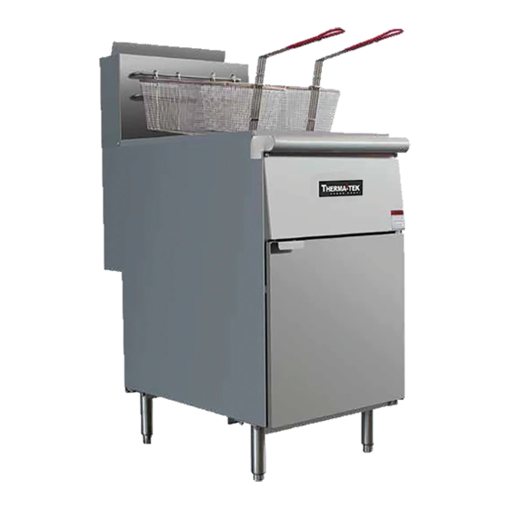
LIQUID SHORTENING GAS FRYERS
Model TEK40 - 3 Tube Burners, 40lb Vat
Model TEK50 - 4 Tube Burners, 50lb Vat
Model TEK70 - 5 Tube Burners, 70lb Vat
INSTALLATION, MAINTENANCE & OPERATING MANUAL
** Either Natural Gas (NG) or Liquid Propane (LP) can supply the fryers **
Remember that Oil & Water won't mix. Don't attempt to fight an Oil Fire using Water.
In the event that a gas odor is detected, shut off the gas supply at the main shut-off valve and contact the
Thank you for choosing our fryers for your operational requirements. Follow these instructions carefully.
If properly used and maintained, you can expect to enjoy years of reliable, efficient and top quality use.
Note: Product line is subject to ongoing, continuous upgrades and improvements. The specifications defining
each model are subject to change without notice.
Keep this manual for training and as a reference guide when service or maintenance is required.
Keep a copy of your Bill of Sale and final building inspection report for the fryer installation as both will help
establish your appliance's warranty period and the date this coverage started.
(covers both Stationary and Mobile Applications)
local gas company or your gas provider/supplier for service!
Manual Date 05/30/19
PRINTED in USA
( 90,000 btu/hr)
(120,000 btu/hr)
(150,000 btu/hr)
Advertisement
Table of Contents

Related Manuals for Therma-tek TEK40

Summary of Contents for Therma-tek TEK40
- Page 1 Manual Date 05/30/19 PRINTED in USA LIQUID SHORTENING GAS FRYERS Model TEK40 - 3 Tube Burners, 40lb Vat ( 90,000 btu/hr) Model TEK50 - 4 Tube Burners, 50lb Vat (120,000 btu/hr) Model TEK70 - 5 Tube Burners, 70lb Vat (150,000 btu/hr) INSTALLATION, MAINTENANCE &...
-
Page 2: Table Of Contents
TABLE OF CONTENTS WARNING IF A GAS ODOR IS DETECTED – (Precautionary actions to take) COVER PAGE IMPORTANT FOR YOUR SAFETY INTRODUCTION General Ordering Parts Fryer Capacity Unpacking INSTALLATION Clearances Location Fryer Capacity Flue Installation CODES AND STANDARDS ASSEMBLY Flue Exhaust Gas Connection Gas Pressure Testing the Gas Supply Piping Connection... -
Page 3: Important For Your Safety
IMPORTANT FOR YOUR SAFETY Proper operation/performance of your liquid shortening gas fryer. READ THE INSTALLATION, OPERATING AND MAINTENANCE INSTRUCTIONS THOROUGHLY BEFORE INSTALLING, MAINTAINING, RESETTING, MONITORING, OPERATING OR SERVICING THIS EQUIPMENT. THIS MANUAL HAS BEEN PREPARED FOR PERSONNEL QUALIFIED TO INSTALL GAS EQUIPMENT. AFTER CAREFULLY REVIEWING AND FOLLOWING THE INSTRUCTIONS/DIRECTIONS IN THIS MANUAL, ONLY QUALIFIED PERSONNEL THAT HAVE READ THIS MANUAL SHOULD PERFORM THE INITIAL FIELD START-UP AND EQUIPMENT ADJUSTMENTS . -
Page 4: Introduction
INTRODUCTION GENERAL Our commercial gas fryers are produced with quality workmanship and materials. Proper installation, usage and maintenance will result in years of satisfactory, cost effective performance producing flavorful, high quality, delicious fried food for your operation. This manual is applicable to a model listed on the cover page. Procedures in this manual apply to all models unless specified. -
Page 5: Installation
INSTALLATION Before installing the fryer, verify that the type of gas (natural or liquid propane [LP]) agrees with the specifications on the fryer data plate. The fryer data plate is located on the inside of the door panel. Make sure the fryer is configured for the proper elevation (height above sea level) of the facility. Record the gas fryer model and serial number for future reference in the space provided below. -
Page 6: Flue Installation
FLUE INSTALLATION: BEFORE USING FRYER INSTALL AND ASSEMBLE THE 10-5/8” FLUE AND DEFLECTOR PLATE TO THE FRYER. 1. Unpack the flue box and flue wrap 2. Slide the flue box over the flue and secure it with the two self-tapping screws using a 5/16” socket 3. -
Page 7: Codes And Standards
CODES AND STANDARDS The fryer must be installed in accordance with all applicable national and local codes, regulations and ordinances. A final building and fire protection inspection should be conducted and the installation approved prior to putting the new fryer into service. In the United States: State and local codes, or in the absence of local codes, comply with: •... - Page 8 • Clearance above the fryer should be adequate for all combustion byproducts to be removed efficiently and safely without creating a potential fire hazard. No structural material on the fryer or its flue chimney including physical alterations should be made so it can be placed under an approved exhaust hood with fire protection •...
-
Page 9: Gas Pressure
GAS PRESSURE (ALL MODELS): Natural Gas, Town Gas or LP {Liquid Propane Gas} The gas pressure must be set at 4” W.C. (Water Column) (0.8 kPa) for natural gas and 10” W.C. (2.75 kPa) for gas. If incoming pressure exceeds ½ PSI (3.45 kPa), an additional pressure regulator must be installed. {Meeting this requirement is the owner’s responsibility} The name plate indicates which form of gas fuel supply is to be connected to this fryer LP or Natural Gas All gas piping should be performed by a licensed plumber and approved by an authorized local building code... -
Page 10: Leveling The Fryer
If disconnecting the restraining device is needed for servicing or cleaning the unit, reconnect the restraining device after the fryer is placed back into its original position. • The fryer must use with an approved restraint cable and quick disconnect gas supply flexible hose connector complying with all applicable codes. -
Page 11: Operation
OPERATION Hot oil and parts can cause burns. Use care when operating, cleaning and servicing the fryer. Spilling hot frying compound or boil out solution can cause severe burns. Do not move the fryer without draining all frying compound and liquid from the tank. Note: Hot oil can splash, foam or splatter out of the fryer if moved or even stationary creating a potential burn and slip and fall hazard condition. -
Page 12: Lighting The Pilot
1. Close the drain valve. 2. Fill the fryer tank with liquid shortening. 3. Shortening level should be between the min and max lines in the fryer tank. 4. Shortening will expand when heated. Do not fill the fryer tank (vat or pot) past the MAX line. Add fresh shortening as needed to maintain oil level. -
Page 13: Turning On The Fryer
TURNING ON THE FRYER 1. Set the temperature knob to desired temperature. 2. After the set temperature is reached, the thermostat shuts off the gas flow to the burners. 3. The pilot remains lit. The burners cycle on and off, to maintain the temperature at the set point. TURNING OFF THE FRYER 1. -
Page 14: Extended Shortening Life
EXTENDING SHORTENING LIFE Shortening life can be extended by the following guidelines: o Do not salt foods over the fryer o Use good-quality shortening o Filter shortening daily (at a minimum) o Replace shortening if it becomes poorly flavored o Keep equipment and surrounding clean o Set thermostat correctly, lower the temperature to 210°F (99°C) during idle periods o Remove excess moisture and particles from food products before they’re fried. -
Page 15: Cleaning
CLEANING Hot oil and hot parts can cause burns. Use care when operating, cleaning, and servicing the fryer. Do not use chlorine or sulfate/sulfide cleaners. GAS FRYER MAINTENANCE & SANITATION CALENDAR Daily Tasks: Clean your fryer regularly with the tank brush along with a damp cloth, and polish with a soft dry cloth. -
Page 16: Boil Out Procedure
Semi-annual Task: 1. Confirm the high limit safety and pilot thermopile safeties are functional 2. Clean the burner orifices and re-tune 3. Run a burner test- [confirm the gas consumption is with-in 2% of the original value at time of commissioning] 4. -
Page 17: Flue Vent Inspection & Maintenance
FLUE VENT INSPECTION & MAINTENANCE Hot oil and hot parts can cause burns. Use care when operating, cleaning, and servicing the fryer. Spilling hot oil or fryer boil out solution or compound can cause severe burns. Do NOT move a fryer without draining all frying compound and liquid from the tank. CAUTION: A dirty fry vat or clogged tube burner orifice may negatively impact the finished fried food quality, the fryer performance and its capacity. -
Page 18: Warranty
PRICES: All prices are subject to change without notice. Prices do not include sales or any other local state tax. All prices are in U.S. Dollars. TERMS: Net 30 days subject to Therma-Tek credit department approval. All amounts past due are subject to 1 1⁄2% per month service charge LIMITED WARRANTY: TWO (2) YEAR PARTS AND LABOR FOR U.S. -
Page 19: Rd Party Approvals
SPECIFICATION & COMMERCIAL DUTY 3 PARTY APPROVALS DIMENSION Width (in) Depth (in) Height (in) Gas Connection (in) Total BTU/hr Model 15.5 14.0 30.3 14.0 47.2 34.7 90,000 3 Tube Burner N&L 15.5 14.0 30.3 14.0 47.2 34.7 120,000 4 Tube Burner N&L 21.0 18.0 30.3 14.0... -
Page 20: Diagrams, Exploded Views
DIAGRAMS, EXPLODED VIEWS EXPLODED VIEW With Replacement/Accessory Part Numbers 1. Gas Parts for Fryer ( 5 tube shown) Part Number Description Part of 14031A Knob, for thermostat 16031A Thermostat, High Limit 450 F Safety, 14031A Mili-volt Thermostat for Fryer , Regulates Temperature 200 ~ 400 Adaptor , 1/2"... - Page 21 2. Tank Parts (5 tube shown) Part Number Description 36031A Screen, crumb, 3 and 4 tube fryer 36033A Screen, crumb, 5 tube fryer 30031A Tank, 3 tube fryer (excluding flue) 30032A Tank, 4 tube fryer (excluding flue) 30033A Tank, 5 tube fryer (excluding flue) 35031A Valve, Ball 35032A...
- Page 22 3. Other Parts ( Including Optional castor installation parts) Part Number Description 40031A Door assembly, complete, 3 and 4 tube 40033A Door assembly, complete, 5 tube 41031A Magnet for door 51031A Basket double, 3 and 4 tube fryer 51033A Basket double, 5 tube fryer 52031A Leg , 6”, adjustable, 1 set...
- Page 23 Burner Carbon Deposits are caused by the wrong size supply orifice, an improper pressure set up or an obstructed flue. Vibration & shock such as slamming the access door or shaking/hitting the fry basket on the fryer top surface may cause the high limit safety switch to open– additional cushioning may help absorb these vibrations and shock The free standing liquid shortening Gas Fryers come on 6”...
-
Page 24: Electrical Control Schematic Diagram (Describes Mili-Volt System)
ELECTRICAL CONTROL SCHEMATIC DIAGRAM (Describes Mili-volt System) This Gas Fired Appliance doesn’t need a wall outlet (electrical service) connection DESCRIPTIVE DRAWING OF THE FRY TANK Plan View of a Fry Tank showing typical 30,000 BTU/Hour Tube Burners, the thermostat & a High Limit Sensor Cutaway View of a Fryer Tank showing the Hot Oil Fry Zone, Tube Burner Middle Zone with Thermostat &... -
Page 25: Safety Apparel (Recommended)
Typical Fry Baskets and Basket Hangers Needed Fryer Protective Apparel – Gloves & Face Shield Always wear and use appropriate safety gear & tools when servicing the Fryer Hot Oil Can Cause Severe Burns Recommended or Factory Approved Accessories can be ordered by calling 1-877-600-8401. Our line of accessories include safety apparel (gloves, face shield and apron), a digital long stem thermometer for calibrating and checking the thermostat, high temperature cleaning brushes, a filter bag, casters, an auxiliary container to hold the tank contents when cleaning or filtering the hot oil, quick connect gas supply... -
Page 26: Tuning The Gas Control System Components
4. Casters with quick disconnect gas hose & restraining cable allows unit to be easily moved for cleaning 5. Vat cover to help minimize gas consumption yet keep the fryer in state of operational readiness 6. Joining strip to interlock 2 side by side fryers and prevent oil dripping/seepage onto their lateral side walls 7. - Page 28 It is suggested that an accurate digital long Stem Thermometer be used to calibrate the thermostat. If the pilot flame is extinguished, the Thermopile will sense the situation and shut off gas at the automatic gas valve. The high Limit safety is factory set at 450°F (232°C). If the oil temperature reaches this value, the sensor shuts off the supply of gas at the automatic gas valve –...
Need help?
Do you have a question about the TEK40 and is the answer not in the manual?
Questions and answers