Table of Contents
Advertisement
Preface
Thank you for your continuous use and support of our company's products. Our
company's R&D group's long-term technical collaboration with domestic
research institutes and the world's major companies enables us to steadily work
on the research and development of various products. Indeed, Shihlin Electric's
FA related products have reached international standard.
With years of effort in promoting inverters and accommodating customer
requirements, as well as detailed planning and design, now we are launching the
SS2-021/SS2-023/SS2-043 series inverter. Whether it is product R&D stage,
final product verification, or product manufacturing, all the processes are
conducted under tight and systemic control. The quality of Shihlin Electric
products wins customer trust, and thus Shihlin Electric products are your best
choice.
Please contact us if you have any special need.For tasks entrusted by our
customers, we will design inverters specifically meeting the customers' needs in
a short period of time with excellent professional background and rigorous
attitude.
To fully deliver the superior performance of the products as well as for the safety
considerations for people and equipments, please read this manual carefully and
keep it for later calibration or maintenance.
Advertisement
Table of Contents

Subscribe to Our Youtube Channel
Related Manuals for Shihlin electric SS2-021 Series


Summary of Contents for Shihlin electric SS2-021 Series
- Page 1 The quality of Shihlin Electric products wins customer trust, and thus Shihlin Electric products are your best choice. Please contact us if you have any special need.For tasks entrusted by our...
-
Page 2: Table Of Contents
Contents 1. User Manual................................1 2. Product Examination..............................3 2.1 Nameplate Instruction ............................ 3 2.2 Type instruction.............................. 3 2.3 Indent Symbol Instruction..........................3 3. Introduction of Shihlin Inverter ..........................4 3.1 Electric Specification ............................. 4 3.2 Common Specification (Inverter Characteristics)..................6 3.3 Mechanical Dimensions.......................... - Page 3 5.21 Up-to-frequency Sensitivity (P.41)......................82 5.22 Output Frequency Detection (P.42, P.43) ....................82 5.23 AM Terminal (P.54~P.56, P.190, P.191) ....................83 5.24 Restart Function (P.57, P.58, P.150) ......................84 5.25 Input Signal Filter Constant (P.60)......................85 5.26 Remote Control Function (P.61) ....................... 86 5.27 Zero Current Detection (P.62, P.63) ......................
- Page 4 5.61 Accumulative motor operation time function (P.292, P.293) ..............120 5.62 Password Protection Function (P.294 and P.295)..................121 5.63 Motor Control Mode (P.300 and P.301) ....................121 5.64 Motor Parameter (P.302~P.309) ....................... 123 5.65 Parameter Copy Function (P.994 and P.995) (DU06 operation panel needs to be purchased)....124 5.66 Alarm Log Deletion (P.996) ........................
-
Page 5: User Manual
Please read the manual carefully to master the roperation methods of the inverter. In case there is any question, please feel free to contact us. In Chapter 3 of this manual, all series and the corresponding specifications of Shihlin Electric SS2-TYPE inverters are listed in detail. - Page 6 User Manual User Manual 5. The difference between ‘on’ and ‘turn on’: Both ‘on’ and ‘turn on’ are used for explaining the function for the Multi-function controlterminal. The word ‘on’ is used to describe the state; that is, the external switch of the terminal is in the closed state.
-
Page 7: Product Examination
FREQ. Range : 0.1~650Hz Serial NO. SD00001 MFG. NO. : S2L0072 Suzhou Shihlin Electric & Engineering Co.,Ltd 2.2 Type instruction 0.75K Suitable motor : 0.4 K : 0.4 kW ; 0. 75 K : 0. 75 kW …… Input voltage :... -
Page 8: Introduction Of Shihlin Inverter
Introduction of Shihlin Inverter Introduction of Inverter 3. Introduction of Shihlin Inverter 3.1 Electric Specification 3.1.1 220V Series Single-Phase Model SS2-021- 0.4K 0.75K 1.5K 2.2K Applicable Motor Capacity 0.75 Rated output capacity kVA (Note) 0.95 Rated output current A (Note) Output 150% 60 seconds;... - Page 9 Introduction of Shihlin Inverter Introduction of Inverter 3.1.3 440V Series Three-Phase Model SS2-043- 0.75 Applicable Motor Capacity 0.75 Rated output capacity kVA (Note) Rated output current A (Note) Output 150% 60 Seconds; 200% 1 Second (reverse time Over-current capability characteristics) Maximum output voltage 3 Phase 380~480V Rated power voltage...
-
Page 10: Common Specification (Inverter Characteristics)
Introduction of Shihlin Inverter Introduction of Inverter 3.2 Common Specification (Inverter Characteristics) Control Method SVPWM control, V/F control, facility vector control. Output Frequency Range 0. 1~650Hz (The starting frequency setting range betwee 0 and 60Hz). Digital If the frequency value is set below 100Hz, the resolution will be 0.01Hz. setting If the frequency value is set above 100Hz, the resolution will be 0.1Hz. - Page 11 Introduction of Shihlin Inverter Introduction of Inverter Running status Output frequency monitoring, output current monitoring, and monitoring output voltage monitoring. HELP mode Alarm history monitoring. Operation Run indication lamp, frequency monitoring indication lamp, Panel LED indication voltage monitoring indication lamp, current monitoring indication lamp(6) lamp, mode switching indication lamp, and PU control indication lamp.
-
Page 12: Mechanical Dimensions
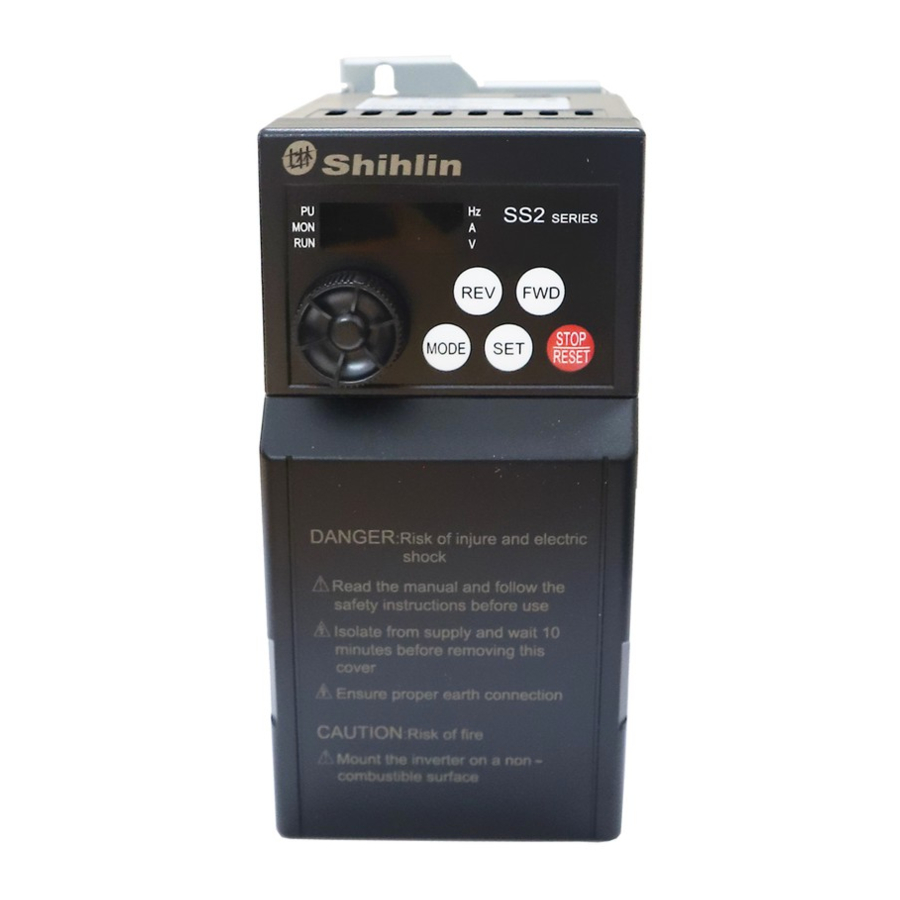
Introduction of Shihlin Inverter Introduction of Inverter 3.3 Mechanical Dimensions 3.3.1 Frame A DANGER: Risk of injure and electric shock Read the manual and follow the safety instructions before use Isolate from supply and wait 10 minutes before removing this cover Ensure proper earth connection CAUTION: Risk of fire... - Page 13 Introduction of Shihlin Inverter Introduction of Inverter 3.3.2 Frame B DANGER: Risk of injure and electric shock Read the manual and follow the safety instructions before use Isolate from supply and wait 10 minutes before removing this cover Ensure proper earth connection CAUTION: Risk of fire Mount the inverter on a non combustible...
-
Page 14: Name Of Each Part
2.2KW FREQ. Range : 0.1~650Hz Serial NO. SD00001 MFG. NO. : S2L0072 Suzhou Shihlin Electric & Engineering Co.,Ltd 3.4.2 Names of the components DANGER: Risk of injure and electric shock Read the manual and follow the safety instructions before use... - Page 15 Introduction of Shihlin Inverter Introduction of Inverter Note: 1. The enlarged figure of the control-circuit terminal block is as follows: the main circuit 2. The enlarged figure of terminal block is as follows:...
-
Page 16: Installation And Wiring
Introduction of Shihlin Inverter Introduction of Inverter 3.5 Installation and Wiring 3.5.1 Transport Transport the inverter by holding the fuselage instead of the cover or any other part of the inverter, or it may be dropped and damaged. 3.5.2 Stockpile This product before installing must be placed in the packaging. - Page 17 Introduction of Shihlin Inverter Introduction of Inverter In general, signal wires (weak) and power lines (heavy) are located in the control cabinet. For inverters, the electric line of force is divided into incoming lines and tail wires. For wiring, signal wires and power lines should be distributed in different and closed region (within 20cm).
- Page 18 Introduction of Shihlin Inverter Introduction of Inverter 3.5.4 Installation notice 1. Please install in an upright direction. 2. Clear the surroundings when installing. 10cm Shihlin Inverter DANGER: Risk of injure and electric shock Read the manual and follow the safety instructions before use Isolate from supply and wait 10 minutes before removing this cover...
- Page 19 Introduction of Shihlin Inverter Introduction of Inverter Orbit determination installation: 1. Orbit determination installation 2. Orbit determination removes 3. Orbit determination installation side by side...
- Page 20 Introduction of Shihlin Inverter Introduction of Inverter Installation with screws: Note: 1. Please choose the screw size M4. 2. Carry out the installation, wire arrangement, dismounting and maintenance by qualified electrical professional personnel. 3. Follow the installation notice. In case the installation notice has not been fully complied with and damage of the inverter or dangerous accidence thus be resulted in, our company will not undertake any legal responsibility.
- Page 21 Introduction of Shihlin Inverter Introduction of Inverter 3.5.5 System wire arrangement Power Please follow the specific Power power supply requirement supply FUSE/NFB shown in this manual. There may be an inrush current during power up . Fuse/NFB Please refer to 3.6.1 and Magnetic contactor select the correct fuse /NFB.
- Page 22 Introduction of Shihlin Inverter Introduction of Inverter 3.5.6 Terminal wire arrangement NFB/MCCB U/T1 R/L1 A.C. V/T2 MOTOR S/L2 Power reator W/T3 input T/L3 Brade resistor RUN forward RUN reverse Reset Red light Control Multi-seped 1 Green light terminals Multi-seped 2 Multi-seped 3 VDC 30 V VAC230V...
- Page 23 Introduction of Shihlin Inverter Introduction of Inverter Note: 1. For multi-function control terminals, please refer to P.80~P.84, P.86, and for multi-function output terminals, please refer to P.40 in Chapter 5. 2. For SS2-TYPE series inverters, the multi-function control terminals have both the sink input mode and the source input mode.
- Page 24 Introduction of Shihlin Inverter Introduction of Inverter If the source input mode is selected, the function of the multi-function control; terminal is active when it is shorted with PC or connected with the external PLC. At this mode, the current flows into the corresponding terminal when it is ‘on’.
- Page 25 Introduction of Shihlin Inverter Introduction of Inverter Note: 1. For SS2-TYPE series of inverters, brake resistor is not included. For information related to brake resistor, please refer to 3.6.3. 2. For information related to regenerative voltage, please refer to P.30 in Chapter 5.
- Page 26 Introduction of Shihlin Inverter Introduction of Inverter Control terminals Terminal Function Terminal Type Remarks and Function Description Name Name Optional Optional These terminals are multi-function control terminals Optional SINK/SOURCE mode switchable . For detailed descriptions, please refer to P.80~P.84, P.86 Optional Chapter 5.
- Page 27 Introduction of Shihlin Inverter Introduction of Inverter 3.5.7 Wiring precautions Main circuit wiring: 1. Do not connect the power supply wires to the inverter output terminals U/T1-V/T2-W/T3 that are designed for connecting motors; otherwise, the inverter may be damaged. 2. Please do not mount filtering capacitors, surge absorbers and electromagnetic contactors at the output end of the inverter.
- Page 28 Introduction of Shihlin Inverter Introduction of Inverter 5. Wiring installation Slotted screwdriver First insert slotted screwdriver with terminal blocks, pressing terminal blocks down, and then insert the electric wires. 6. Wiring demounting Slotted screwdriver First insert slotted screwdriver with terminal blocks, and pressing terminal blocks down, and then pull out the wire.
-
Page 29: Selection Of Peripheral Equipments
Introduction of Shihlin Inverter Introduction of Inverter 3.6 Selection of Peripheral Equipments 3.6.1 No-fuse switch Power Source Applicable NFB/MCCB Applicable MC Inverter Type Motor Capacity Capacity Type (Shihlin) Type (Shihlin) SS2-021-0.4K 220V 0.5HP 1.5kVA BM30SN3P5A S-P11 SS2-021-0.75K 220V 1HP 2.5kVA BM30SN3P10A S-P11 SS2-021-1.5K... - Page 30 Introduction of Shihlin Inverter Introduction of Inverter 3.6.2 Power cable specification/pressing connection terminals specification Power Cable Specification Pressing connection terminal (PVC cables standard) specification (used by powe cables) Power supply terminal Loading terminal Inverter Type (R/L1- S/L2- T/L3) (U/T1-V/T2-W/T3) Power supply Loading Crimping Tightening...
- Page 31 Introduction of Shihlin Inverter Introduction of Inverter 3.6.3 Brake resistors Inverter Type Brake Resistor Specification Inverter Type Brake Resistor Specification SS2-021-0.4K 100W 220 SS2-023-3.7K 400W SS2-021-0.75K 150W 120 SS2-043-0.4K 80W 1000 SS2-021-1.5K 300W SS2-043-0.75K 100W 800 SS2-021-2.2K 300W SS2-043-1.5K 200W 320 SS2-023-0.4K 100W 220 SS2-043-2.2K...
- Page 32 Introduction of Shihlin Inverter Introduction of Inverter 3.6.5 Zero-phase reactor UNIT:mm P41T63*38*25C Motor Capacity Recommended Wire Inverter Type Qty. Wiring Method Size (mm 0.5-5.5 0.75 220V Diagram A Single- phase 3.5-5.5 0.5-5.5 0.75 220V Diagram A Three- phase 0.75 0.5-5.5 440V Diagram A Three-phase...
- Page 33 Introduction of Shihlin Inverter Introduction of Inverter 3.6.6 Input/output reactor Input AC Line Reactor 220V 50/60Hz Three-phase Rated Amps of 2% Impedance Reactor Types 4% Impedance Reactor Types Inverter ACL-0005-EISC-E3M8 ACL-0005-EISC-E5M6 0.75 ACL-0005-EISC-E3M8 ACL-0005-EISC-E5M6 ACL-0010-EISC-E1M5 ACL-0010-EISC-E2M8 ACL-0015-EISC-E1M0 ACL-0015-EISC-E1M9 17.5 ACL-0020-EISC-EM75 ACL-0020-EISC-E1M4 440V 50/60Hz Three-phase Rated Amps of...
- Page 34 Introduction of Shihlin Inverter Introduction of Inverter 220V 50/60Hz Three-phase Rated Amps of 1% Impedance Reactor Types 2% Impedance Reactor Types Inverter OCL-0005-EISC-E1M4 OCL-0005-EISC-E2M8 0.75 OCL-0005-EISC-E1M4 OCL-0005-EISC-E2M8 OCL-0010-EISC-EM70 OCL-0010-EISC- E1M4 OCL -0015-EISC-EM47 OCL -0015-EISC-EM93 17.5 OCL -0020-EISC-EM35 OCL -0020-EISC-EM70 440V 50/60Hz Three-phase Rated Amps of 1% Impedance Reactor Types 2% Impedance Reactor Types...
-
Page 35: Primary Operation
Primary Operation Primary Operation 4. Primary Operation 4.1 Operation Modes of the Inverter The operation modes are related to the reference source of the target frequency and the signal source of the motor starting. Shihlin SS2-TYPE inverter has a total of 9 kinds of operation modes, namely, PU mode, JOG mode, external mode, communication mode, combined mode 1, combined mode 2, combined mode 3, combined mode 4 and combined mode 5. - Page 36 Primary Operation Primary Operation Related Operation Reference Source of Target Signal Source of Motor Values Remarks Parameters Mode Frequency Starting Combined mode 1 operation panel External terminals External voltage/current Combined signal, combination of Press the key mode 2 multi-speed stage levels or frequency set by pulse the operation panel.
- Page 37 Primary Operation Primary Operation 4.1.1 The flow chart for transferring operation modes with operation panel Note: 1. At the PU mode, the indicating lamp in the operation panel will be lit up. 2. At the external mode, the display screen will display 3.
- Page 38 Primary Operation Primary Operation Note: 1. For detailed operating flow at monitoring mode, please refer to Section 4.1.3. 2. For detailed operating flow at frequency setting mode, please refer to Section 4.1.4. 3. For detailed operating flow at parameter setting mode, please refer to Section 4.1.5.
- Page 39 Primary Operation Primary Operation 4.1.5 Operating flow chart for the parameter setting mode with operation panel The third bit flashes The second bit flashes The first bit flashes Over 0.5 s Enter the next Read new set value Read previous set value setting mode Set value written and it flashes...
-
Page 40: Basic Operation Procedures For Different Modes
Primary Operation Primary Operation 4.2 Basic Operation Procedures for Different Modes 4.2.1 Basic operation procedures for the PU mode (P.79=0 or 1 ) • Change the operation mode to PU mode, and the indicating lamp of will be lit up. Note: 1. - Page 41 Primary Operation Primary Operation • Turn on STF or STR To run the motor. • At this time, the indicating lamp of will flicker, indicating that the motor is running. Note: 1. Please refer to P.78 and multi-function terminal P.80~P.84, P.86 in Chapter 5 for advanced setting for starting terminals STF and STR.
- Page 42 Primary Operation Primary Operation 4.2.5 Basic operation procedured for combined mode 1 ( , P.79=4 ) • At the combined mode 1, the indicating lamp of will flicker. Note: Please refer to Section 4.1 for selecting and switching the operation modes, •...
- Page 43 Primary Operation Primary Operation 4.2.7 Basic operation procedures for combined mode 3 ( , P.79=6) The target frequency is determined by communication. hen M0, M1, M2 and REX are ‘On’, the target frequency will be determined by the combination of multi-speed stage levels (Please refer P.86).
-
Page 44: Operation
Primary Operation Primary Operation 4.3 Operation 4.3.1 Checking and preparation before operation Examine the following aspects before the operation: 1. Check the wiring. Make sure that the AC motor driver output terminals (U/T1-V/T2-W/T3) are not connected to the power and the grounding terminals are well grounded. 2. - Page 45 Primary Operation Primary Operation 4.3.3 Trial Run Check the cables and make sure that there are no abnormalities before the operation. The inverter will be at the external mode after turning on the power. 1. After turning on the power, make sure that Operation panel shown no fault, the indicating lamp of are all lit up when the keyboard panel is not chosen.
-
Page 46: Parameter Description
Parameter Description Parameter Description 5. Parameter Description 5.1 Torque Boost (P.0, P.46) P.0 “Torque Boost” P.46 “Second Torque Boost” P.3 Base frequency P.19 Base Voltage P.47 Secone base frequency P.80~P.84, P.86 Multi-function terminals selection For an inverter controlled by the V/F mode, the starting torque is usually inadequate when starting the motor because the output voltage of the inverter is inadequate. -
Page 47: Range Of The Output Frequency
Parameter Description Parameter Description 5.2 Range of the Output Frequency (P.1, P.2, P.18) P.1 “Maximum frequency” P.13 Starting frequency P.2 “Minimum frequency” P.18 “High-speed maximum frequency” The upper limit and the lower limit of the output frequency can be restricted. Parameter Factory Setting Setting Range... -
Page 48: Base Frequency And Base Voltage
Parameter Description Parameter Description 5.3 Base Frequency and Base Voltage (P.3, P.19, P.47) P.3 “Base Frequency” P.14“Load pattern selection ” P.19 “Base Voltage” P.80~P.84, P.86 P.47 “Second base frequency” “Multi-function terminals selection ” P.189“Default function ” The maximum output voltage of the inverter is referred to as the base voltage. If the output frequency is lower than the base frequency, the output voltage of the inverter will increase with the output frequency. -
Page 49: Multi-Speed
Parameter Description Parameter Description 5.4 Multi-speed (P.4~P.6, P.24~P.27, P.142~P.149) P.4 “Speed 1(high speed)” P.1 Maximun frequency P.5 “Speed 2(medium speed)” P.2 Minimum frequency P.6 “Speed 3 (low speed)” P.29 Acceleration/deceleration pattern selection P.24~P.27 “Speed 4 to 7” P.79 Operation mode selection P.142~P.149 “Speed 8 to 15”... -
Page 50: Acceleration/Deceleration Time
Parameter Description Parameter Description • Provided that the values of P.24~P.27 and P.142~P.149 are all defaulted, the ‘3-speed operation’ is active. In this case, the target frequency can be set as follows (the priority for the terminals is RL RM RH): Parameter P.24= P.25=... - Page 51 Parameter Description Parameter Description Parameter Factory Setting Setting Range Remarks 5s 3.7KW and below 0~360s When P.21=0 10s 5.5KW 0~3600s When P.21=1 5s 3.7KW and below 0~360s When P.21=0 10s 5.5KW 0~3600s When P.21=1 50Hz When P.189=1 1~650Hz 60Hz When P.189=0 Minimum setting increment:0.01s 0, 1 Minimum setting increment:0.1s...
-
Page 52: Electronic Thermal Relay Capacity
Parameter Description Parameter Description 5.6 Electronic Thermal Relay Capacity (P.9) P.9 “Electronic thermal relay capacity” P.80~P.84, P.86 “Multi-function terminals selection ” To simulate a thermal relay to prevent the motor from overheating, the electronic thermal relay employs a built-in program. Parameter Factory Setting Setting Range... -
Page 53: Starting Frequency
Parameter Description Parameter Description <Setting> • The stop signal (please refer to Chapter 4 for the primary operation) will cause a gradual decrease of the output frequency of the inverter. In case the output frequency reaches the DC injection brake operation frequency (P.10), the DC injection brake will be activated. -
Page 54: Load Pattern Selection
Parameter Description Parameter Description Output frequency (Hz) P.13 Time Start signal 5.9 Load pattern selection (P.14, P.98, P.99, P.162~P.169) P.14 “Load pattern selection” P.167 “Voltage output at medium P.98 “Medium frequency 1” frequency 4” P.99 “Voltage output at medium P.168 “Medium frequency 5” frequency 1”... - Page 55 Parameter Description Parameter Description <Setting> • If P.14=4, P.19=220V, P.98=5Hz and P.99=10%, the output voltage equals to P.99 P.19=10% 220V=22V when the inverter is run at 5Hz. • P.46 Second Torque Boost is valid if RT is on. P.14 0 P.14 1 P.19 P.19...
- Page 56 Parameter Description Parameter Description P.14 6 7 8 P.14 9 10 P. 19 P. 19 Output frequency Output frequency P. 3 P. 3 When P.14=6, A is 8.7%; when P.14=7, A is When P.14=9, A is 20.0%; when P.14=10, A is 10.4%;...
-
Page 57: Jog Mode
Parameter Description Parameter Description 5.10 JOG Mode (P.15, P.16) P.15 “JOG frequency” Related parameters P.20 “Acceleration /deceleration P.16 “JOG acceleration/deceleration reference frequency ” time” P.21 “Acceleration/deceleration time increments ” At the JOG mode, the output frequency is the set value of P.15, and the acceleration/deceleration time is the set value of P.16. -
Page 58: Output Frequency Filtering Constant
Parameter Description Parameter Description Parameter Factory Setting Setting Range Remarks - - - When P.23=99999, stall prevention 9999 0~200%, 9999 operation level is the set value of P.22. P.189=1 0~650Hz 60Hz When P.189=0 <Setting> • During the period of starting a motor or increasing the output frequency, the output current of the inverter will increase. -
Page 59: Acceleration/Deceleration Pattern Selection
Parameter Description Parameter Description 5.13 Acceleration/deceleration Pattern Selection (P.29) P.29 “Acceleration/deceleration Related parameters P.3 “Base frequency” pattern selection” P.7 “Acceleration time” P.8 “Deceleration time” P.20 “Acceleration/deceleration reference frequency” P.44 “Second acceleration time” P.45 “Second deceleration time” Parameter Factory Setting Setting Range Remarks - - - <Setting>... -
Page 60: Regenerative Brake
Parameter Description Parameter Description Time Note: This pattern is applicable to the mainframes of working machines. • The S-shape acceleration/deceleration curve 2 when P.29=2 An acceleration slope is formed by combining and P.20. A deceleration slope is formed by combining and P.20. -
Page 61: Carrier Frequency Action Choice
Parameter Description Parameter Description There is a built-in transistor (a.k.a. brake transistor) in the inverter. The conducting time ratio of the transistor is referred to as the regenerative brake duty. The higher the regenerative brake duty is, the more energy the brake resistor consumes, and the stronger the brake capability is. i t t i t t If regenerative brake duty is 3% fixed, the value... -
Page 62: Communication Function
Parameter Description Parameter Description 5.16 Communication Function (P.32, P.33, P.36, P.48~P.53, P.153~P.154) P.32 “Serial communication Baud rate selection” P.33 “Communication protocol selection” P.36 “Inverter station number” P.48 “Data length” P.49 “STOP bit length” P.50 “Parity check selection” P.51 “CR, LF selection” P.52 “Number of communication retries”... - Page 63 Parameter Description Parameter Description Factory Parameter Setting Range Remarks Parameter Setting Only CR CR and LF 0~10 Note 2 Conduct communication overtime test 0~999.8 according to the set value 9999 0~999.8s, 9999 9999: No communication overtime test 9999 Note 3 Warn and call to stop 0, 1 No warning and keep running...
- Page 64 Parameter Description Parameter Description Steps for different communication type with or without data format: Operation Operation Write Read Out Description Reset Monitoring Command Frequency Parameter Parameter Computer sends out communication request to inverter Inverter Data Processing time Data No error responded (request from...
- Page 65 Parameter Description Parameter Description Readout data Information Number Format Stop Station Unit Data no Readout Data Check Character Number error Error Stop Station Code Character Data error Number Inverter’s responding data when the computer performs data reading Information number Format Stop Character Station Number (No data error)
- Page 66 Parameter Description Parameter Description Error Error Item Communication error exception content Code The information the inverter received is a syntax error, or the Protocol Error information is not received within the specified time, or CR and LF codes are different from the initial set. Frame Error The STOP bit the inverter received is different from the initial set.
- Page 67 Parameter Description Parameter Description Step2. The inverter responds to the computer using format C after receiving and processing the data: Station Number H30 H30 Example 3. PC communication for reading P.195: Step1. PC sends inputting page change command to the inverter via format A: Station Number Command Code Data...
- Page 68 Parameter Description Parameter Description Step 4. The inverter responds to the computer using format C after receiving and processing the data. Station Number H30 H30 Example 5. Change the value of P.195 to 500 (parameter range 0~400): Step1 and step 2 of Example 5 are similar to Step1 and Step2 of Example 3. Step 3.
- Page 69 Parameter Description Parameter Description (4). Broadcast The computer designated by address 0 can send a message to all the inverters. All inverters that receive information from the computer will perform the requested function, but they do not send feedback to the computer. 2).
- Page 70 Parameter Description Parameter Description Algorithm of CRC checksum: 1. Installation of a 16-bit register and all bits are 1. 2. The 16-bit operation result, an exclusive OR between the 16-bit register high byte, and the beginning of 8-bit byte, was put into the register. 3.
- Page 71 Parameter Description Parameter Description Normal response Address Function Initial Address Write Data Mode Start Check ASCII 2char 2char 4char 4char 2char 0D 0A >=10ms 1byte 1byte 2byte 2byte 2byte >=10ms Message Content 1 Address Set the address for the information to be sent to. 2 Function code 3 Initial address Set the beginning address of the register that has a writting function.
- Page 72 Parameter Description Parameter Description (4). Abnormal response Abnormal responses are obtained because the query information received from the inverter is incorrect in terms of the function, address and data. Address Function 2 Error Code Mode Start Check H80 Function code ASCII 2char 2char...
- Page 73 Parameter Description Parameter Description Communications examples Example 1 Write CU (communication) mode by Communication Step 1. Modify the inverter mode by the computer Mode Start Address Function Initial Address Write Data Check ASCII H31H30 0D 0A >=10ms 8D 0A >=10ms Step 2.
- Page 74 Parameter Description Parameter Description Example 4 Message from the computer for reading parameters from to P.11: Step 1. The computer requests the inverter to read the value of P.0~P.11. The initial address is H0000. Mode Start Address Function Initial address Register number Check ASCII...
- Page 75 Parameter Description Parameter Description Shihlin Modbus Modbus Item Protocol Information Content and Functions Code Address Code H0000~H00FF b8~b15 reserved b7 Alarm occurrence b6 Frequency detection b5 Parameters to default values end. Inverter State H1001 b4 Overload b3 Frequency achieved b2 Reverse rotation b1 Forward rotation b0 Operation Set frequency...
- Page 76 Parameter Description Parameter Description Shihlin Modbus Modbus Item Protocol Information Content and Functions Code Address Code Operation H06/H10 H0000~H9C40 write in P.430 H1002 frequency write in H5A5A H1104 H9966 H1103 Inverter parameter See parameter recovery H06/H10 and error code H9696 H1106 description table erased.
-
Page 77: Speed Display
Parameter Description Parameter Description The table of the special monitor code i t a . e t . e t H0002 Monitor the voltage which can be input across terminal 2-5. 0.1V H0003 Monitor the voltage/current which can be input across terminal 4-5. 0.01A/0.1V H0004 Monitor the voltage which can be output across terminal AM-5. -
Page 78: Voltage Signal Selection And Target Frequency
Parameter Description Parameter Description 5.18 Voltage Signal Selection and Target Frequency (P.38, P.73, P.139~P.141) P.38 “The maximum output Frequency (the target frequency is set by the input signal across terminal 2-5)” P.73 “Voltage signal selection” P.139 “Voltage signal bias” P.140 “Voltage signal gain” P.141 “Bias polarity of voltage signal and reverse motion of negative bias”... - Page 79 Parameter Description Parameter Description Here are some examples: Example 1: This is the most used setting. When the inverter is at the external mode, the combined mode 2 or the combined mode 4, the frequency is set by terminal 2-5. Max output frequency 60Hz...
- Page 80 Parameter Description Parameter Description Example 4: This example shows a potentiometer range between 0V and 5 V. Instead of adjusting gain as the example below, the user can set P.38 to 120Hz or P.73 to 0 to achieve the same result.
- Page 81 Parameter Description Parameter Description Example 7: In this example, the input is programmed to run a motor in both forward and reverse directions. The motor will idle when the potentiometer position is at the mid-point of the scale. Using the settings in this example to disable the external FWD and REV controls. Max output frequency 60Hz Forward direction...
-
Page 82: The Input Signal Across Terminal 4-5 And The Target Frequency
Parameter Description Parameter Description 5.19 The Input Signal across Terminal 4-5 and the Target Frequency (P.17, P.39) P.17 “Input signals across terminal 4-5 selection” P.39 “The maximum output frequency (the target frequency is set by the input signal across terminal 4-5)” SS2-TYPE series inverters have two analog input channels, terminal 2-5 and terminal 4-5. -
Page 83: Multi-Function Output (P.40, P.64, P.74, P.85, P.120 And
Parameter Description Parameter Description 5.20 Multi-function Output (P.40, P.64, P.74, P.85, P.120 and P.187) P.40 “Multi-function output terminal Related parameters pattern” P.41 “Up-to-frequency sensitivity” P.42 “Output frequency detection P.64 “Pulse output selection” for forward rotation” P.74 “10X output selection” P.43 “Output frequency detection for reverse rotation”... - Page 84 Parameter Description Parameter Description i t c PO2 (Periodical detection): At the programmed operation mode, PO2 signal will be output at the end of each cycle. PO3 (Pause detection): At the programmed operation mode, PO3 signal will be output when the inverter pauses. BP (Inverter output): Switch between the inverter operation and commercial P.40/P.85 power-supply operation function.
- Page 85 Parameter Description Parameter Description • When P.54=3, the output corresponds to the accumulation rate of temperature increase of the inverter. If the temperature of the IGBT module of the inverter is too high and reaches the NTC level, the function of external terminal SO will be FM function and a pulse of 1440Hz will be sent out.
-
Page 86: Up-To-Frequency Sensitivity
Parameter Description Parameter Description 5.21 Up-to-frequency Sensitivity (P.41) Related parameters P.41 “Up-to-frequency sensitivity” P.40 “Multi-function output terminal pattern ” P.85 “Function selection for multi-function relay ” Parameter Factory Setting Setting Range Remarks - - - <Setting> • If P.41=5%, a signal (SU) is output when the output frequency enter the 5% region near the target frequency. -
Page 87: Am Terminal
Parameter Description Parameter Description • If P.42=30 and P.43=9999 (the default value), then a signal (FU) is output when the forward or reverse rotation output frequency exceeds 30Hz. Output frequency Run forward (Hz) P.42 P.43 Time (s) Run reverse Output signal Note: In this section, FU is the function names of the multi-function output terminals. -
Page 88: Restart Function
Parameter Description Parameter Description • When P.54=4, the output corresponds to the electronic thermal rate.If either the electronic thermal relay (when P.9 0) or the electronic thermal relay of the inverter’s IGB module (when P.9=0) is running, and a voltage of 10V will be sent out at terminal AM. output P.55 output frequency P.56 output current... -
Page 89: Input Signal Filter Constant
Parameter Description Parameter Description • Once the motor is automatically restarted, the output frequency of the inverter will be the target frequency, but the output voltage will be zero. Then the voltage will be increased gradually to the expected voltage value. The period for the voltage increase is called the restart voltage rising time (P.58). -
Page 90: Remote Control Function
Parameter Description Parameter Description 5.26 Remote Control Function (P.61) P.61 “Remote setting function selection” If the operation box is located away from the control box, contact signals can be used to perform the continuous variable-speed operation without using analog signals at the external mode, the PU mode, the combined mode 1 or the combined mode 5. - Page 91 Parameter Description Parameter Description 2. At the remote setting, the output frequency of the inverter is: Target Frequency set by external terminals: Frequency set by RH/RM operation external set frequency other than multi-speeds Target Frequency set by operation panel: PU set frequency + external set frequency other than multi-speeds •...
-
Page 92: Zero Current Detection
Parameter Description Parameter Description 5.27 Zero Current Detection (P.62, P.63) Related parameters P.62 “Zero current detection level” P.40 “Multi-function output P.63 “Zero current detection time” terminal pattern ” P.85 “Function selection for multi-function relay ” Parameter Factory Setting Setting Range Remarks 0~200%, 9999 9999: Function invalid... -
Page 93: Brake Selection
Parameter Description Parameter Description Inverter retry is a conditional execution. For example, when the first alarm occurs, the retry will be executed. A second alarm occurs successively within P.68 5 seconds is defined as continuous alarms. The occurrence of a continuous alarm that is more frequent than the pre-defined upper limit indicates a significant malfunction. -
Page 94: Carrier Frequency
Parameter Description Parameter Description • When P.71=0, the brake is idling. The output of the inverter will be terminated immediately after pressing , and the motor will be racing. STOP RESET Motor coasts stop Time Operation signal • When P.71=1, it is now beeline brake. The output of the inverter will follow the acceleration/deceleration curve after pressing STOP RESET... -
Page 95: Stop Function Selection
Parameter Description Parameter Description Rated current 100% 2kHz 4kHz 6kHz 8kHz 10kHz 12kHz 14kHz 16kHz Carrier frequency Note: The optimum carrier frequency shall be eight times greater than the target frequency. 5.31 Stop Function Selection (P.75 P.75 “Stop function selection” Parameter Factory Setting Setting Range... -
Page 96: Parameters Write Protection
Parameter Description Parameter Description 5.32 Parameters write protection (P.77) P.77 “Parameters write protection” Parameter Factory Setting Setting Range Remarks - - - <Setting> • If P.77=0, all parameters except P.188 can be written when the motor stops. When the motor runs, only P.4~P.6, P.24~P.27, P.54~P.56, P.77, P.131~P.138, P.142~P.149, P.161, P.190~P.199, P.223~P.225 P.230, P.232,... -
Page 97: Operation Mode Selection
Parameter Description Parameter Description 5.34 Operation Mode Selection (P.79) P.79 “Operation mode selection” Factory Setting Parameter Remarks Setting Range The PU mode, external mode and JOG mode are valid and interchangeable. The PU mode and JOG mode are active and interchangeable. Only the external mode is valid. - Page 98 Parameter Description Parameter Description Para- Termi Factory Setting Value Function Name Function Description Remarks meter Setting Range At the external mode, combined mode 2 or combined mode 4, the inverter target Please refer frequency is set by P.39 the signal input 0~40 across terminal 4-5 when AU is on.
- Page 99 Parameter Description Parameter Description Para- Termi Factory Setting Value Name Function Instruction meter Setting Range At the external mode, the inverter runs when RUN is on. At the external mode, it is Run forward used with RUN. The inverter runs forwards when STF/STR STF/STR /reverse is on, and runs reversely when...
- Page 100 Parameter Description Parameter Description Note: 1. The default values are: P.80=2 (RL), P.81=3 (RM), P.82=4 (RH), P.83=0 (STF), P.84=1 (STR), P.86=30 (RES). 2. When changing the value of P.80~P.84, P.86, the functions of the terminals will be changed. For example, P.80=2 means that the function of M0 is RL, but if P.80=8, its function changes to RT as a second function selection terminal.
-
Page 101: Slip Compensation Coefficient
Parameter Description Parameter (4) Three-wire control mode2 (with self maintaining function):K1: STOP signal, normally close. If K1 is opened, the inverter will be stoped. K2: RNU signal, normally opened, and the pulse signal is active. If the external terminal corresponds to the parameters settings for 39, the motor will stop until the user starts again when reversing. -
Page 102: Frequency Jump
Parameter Description Parameter 5.37 Frequency Jump (P.91~P.96) P.91~P.96 “Frequency jump” To avoid the system mechanical resonance frequency, three sets of jump frequencies are presented: P.91 and P.92 the first set, P.93 and P.94 the second set, and P.95 and P.96 the third set. Parameter Factory Setting Setting Range... -
Page 103: Programmed Operation Mode
Parameter Description Parameter Description 5.38 Programmed Operation Mode (P.100~P.108, P.111~P.118, P.121~P.123, P.131~P.138) P.100 “Minute/second selection” P.101~P.108 “Runtime of each section” P.111~P.118 “Acceleration/deceleration time of each section” P.121 “Run direction in each section” P.122 “Cycle selection” P.123 “Acceleration/deceleration time setting selection” P.131~P.138 “Frequency of each section”... - Page 104 Parameter Description Parameter Description frequency P.111 P.112 P.113 P.114 P.116 P.118 P.117 P.115 P.118 P.101 P.102 pause P.103 P.104 P.105 P.106 P.107 P.108 • The run direction is set in binary form (8-bit), then translated to decimal form and stored in P.121. ‘1’...
-
Page 105: Operation Panel Frequency Monitoring Selection Function
Parameter Description Parameter Description • The mode of operation is presented in the figure below: P.135 frequency P.132 P.133 P.131 P.134 P.132 P.131 …… Note: 1. The parameter P.100, P.101~P.108, P.111~P.118 and P.121~123 is only for programmed operation mode. In the manually operation circle mode, the acceleration time is determined by P.7, and the deceleration time is determined by P.8. -
Page 106: Zero-Speed Function
Parameter Description Parameter Description Note: When P.110 = 3, the screen display shows two sections. A decimal point is used to separate the boundaries. What is on the left is the target pressure of the constant pressure system and what is on the right is the feedback pressure of the constant pressure system. -
Page 107: External Terminal Filter Function
Parameter Description Parameter Description Parameter Factory Setting Setting Range Remarks No detection of over torque When detecting the over torque, 0~200% 0.1~200% alarm is displayed and the motor stopped. - - - full load current level 100% Output current (%) P.155 Invertor display the OL2 alarm,and the output stopped,the motor stopped too. -
Page 108: Energy-Saving Control
Parameter Description Parameter Description 5.44 Energy-saving Control (P.159) P.159 “ nergy-saving control function” Factory Setting Parameter Setting Range Remarks Normal running mode Energy-saving running mode • At the energy-saving running mode, the inverter will control the output voltage automatically in order to reduce the output power losses when the inverter is running. -
Page 109: Pid Control
Parameter Description Parameter Description 5.46 PID Control (P.170~P.183, P.223~P.225) P.170 “PID selection” P.179 “Sleep detects duration time” P.171 “PID feedback control method P.180 “Revival level” selection” P.181 “Outage level” P.172 “PID proportion Gain” P.182 “Upper integral” P.173 “PID integration Gain” P.183 “Deceleration step length of P.174 “PID differential Gain”... - Page 110 Parameter Description Parameter Description Factory Setting Parameter Remarks Setting Range This gain determines the proportion controller’s impact on 1~100 feedback deviation. The greater the gain, the faster the impact. Yet a gain that is too big will cause vibration. This parameter is use to set integral controller’s integral time. When the integral gain is too big, the integral effect will be too 0~100s weak to eliminate steady deviation.
- Page 111 Parameter Description Parameter Description =P. 172 contravariance e(t) limit =P. 173 filter P.182 =P.174 Output PID module frequency frequency Feedback value feedback quantity convertor When the feedback value is lower than the abnormal deviation level and continue exception duration time P.176, the PID is exceptional. This time the screen will display , and it will select freedom or brakes according to P.177.
-
Page 112: Disconnection Processing Function Of Terminal
Parameter Description Parameter Description <Setting> • PID gain easy setting: (1). Use pure proportional control and increase PID proportion Gain progressively for the system to gain critical concussion. Adjust 80 % PID proportion Gain setting in (1) and increase PID integration Gain progressively (2). -
Page 113: Proportion Linkage Function
Parameter Description Parameter Description 5.48 Proportion Linkage Function P.185 P.185 “Proportion linkage gain” Parameter Factory Setting Setting Range Remarks - - - <Setting> • By external analog signal input terminals on the function of setting frequency multiplier effects. • If many inverters operation proportionally, take advantage of this function on the instructions of the master inverter to the salve inverter for fine-tuning more effective. -
Page 114: Default Function
Parameter Description Parameter Description 5.50 Default Function (P.189) P.189 “Default function” Parameter Factory Setting Setting Range Remarks Apply to the 60Hz system 0, 1 Apply to the 50Hz system The user can select the frequency witch factory setting 50Hz or 60Hz according to the power frequency and the frequency witch motor factory setting. -
Page 115: Input Signal Across Terminal 2-5
Parameter Description Parameter Description 5.51 Input Signal across Terminal 2-5 (P.192~P.195) P.192“Minimum input voltage across terminal 2-5” P.193“Maximum input voltage across terminal 2-5” P.194“Frequency corresponds to the minimum input voltage across terminal 2-5” P.195“Frequency corresponds to the maximum input voltage across terminal 2-5” Parameter Factory Setting Setting Range... -
Page 116: Input Signal Across Terminal 4-5
Parameter Description Parameter Description 5.52 Input Signal across Terminal 4-5 (P.196~P.199) P.196 “Frequency corresponds to the minimum input current/voltage across terminal 4-5” P.197 “Frequency corresponds to the maximum input current/voltage across terminal 4-5 P.198 “Minimum input current/voltage across terminal 4-5” P.199 “Maximum input current/voltage across terminal 4-5”... -
Page 117: Backlash Compensation Function
Parameter Description Parameter Description 5.53 Backlash Compensation Function (P.229~P.233) P.229 “Backlash compensation function selection” P.230 “The backlash acceleration stopping frequency” P.231 “The backlash acceleration stopping time” P.232 “The backlash deceleration stopping frequency” P.233 “The backlash deceleration stopping time” Parameter Factory Setting Setting Range Remarks The function is invalid. -
Page 118: Triangular Wave Function
Parameter Description Parameter Description 5.54 Triangular Wave Function (P.234~P.239) P.234 “Triangular wave function selection” P.235 “Maximum amplitude” P.236 “Amplitude compensation for deceleration” P.237 “Amplitude compensation for acceleration” P.238 “Amplitude acceleration time” P.239 “Amplitude deceleration time” Parameter Factory Setting Setting Range Remarks - - - 0~25%... -
Page 119: Auxiliary Frequency Function
Parameter Description Parameter Description 5.55 Auxiliary Frequency Function (P.240) P.240 “Auxiliary frequency function selection” Parameter Factory Setting Setting Range Remarks - - - <Setting> • When the value of P.240 is 0, auxiliary frequency function is not selected. • When the value of P.240 is 1, operation frequency = basic frequency + auxiliary frequency (2-5), •... -
Page 120: Options For Stopping The Cooling Fan
Parameter Description Parameter Description As shown as follows: Output frequency P.13 time DC injection brake voltage P.244 time P.243 5.57 Options for Stopping the Cooling Fan (P.245) P.245 “Cooling fan operation selection” Parameter Factory setting Setting range Remarks - - - <Setting>... - Page 121 Parameter Description Parameter Description Parameter Factory setting Setting range Remarks 0.1~100s 0.5 s 0.1~100 s 99999 0~60Hz, 99999 99999 0~10Hz, 99999 <Setting> •P.249 is used to switch the frequency from inverter operation to commercial power supply operation. Between starting and P.249 inverter operation, an output frequency greater than P.249 will automatically change the inverter operation to commercial power supply operation.
- Page 122 Parameter Description Parameter Description Warning: 1. MC1 and MC2 must be mechanically interlocked; the running direction of the inverter operation and the commercial power supply operation should be consistent. 2. Use the commercial power operation switchover function under the external operation mode. 3.
-
Page 123: Short Circuit Protection Function
Parameter Description Parameter Description During the automatic switchover, A: P.247 MC Switchover interlocking time; B: P.248 starting waiting time; C: P.57 restarting free operation time; D: P.58 restarting elevating time. Note: 1. When the motor runs at 50Hz (or 60Hz), the commercial power supply will offer a more efficient operation than the inverter will. -
Page 124: Accumulative Motor Operation Time Function
Parameter Description Parameter Description i t t i t t 0~12 The value of P.288, 1~12, corresponds to the abnormal codes of P.289’s alarm E1~E12. When P.290=1, P.291 corresponds to the frequency when the alarm goes off. When P.290=2, P.291 corresponds to the current when the alarm goes off. -
Page 125: Password Protection Function (P.294 And
Parameter Description Parameter Description • P.293 is about the accumulative motor operation time in days. The updated value cannot be modified by executing P.998 or power shutdown. To clear the accumulated time, make P.293=0. 5.62 Password Protection Function (P.294 and P.295) P.294 “Password input”... - Page 126 Parameter Description Parameter Description • When P.300=0, no motor parameter auto-tuning function is required for normal V/F curve operation. • For general magnetic vector control, please set P.300 to 2. The frequency will be altered due to elevated voltage and increased compensatory motor load. •...
-
Page 127: Motor Parameter
Parameter Description Parameter Description • If you need real sensorless vector control, you should set P.300 to 3. Note: 1.The motor capacity has to be at the same level or one level below of the level of the capacity of the inverter. 2. -
Page 128: Parameter Copy Function (P.994 And P.995) (Du06 Operation Panel Needs To Be Purchased)
Parameter Description Parameter Description Note: 1. When the inverter is used with a motor of a different level, verify the input motor’s nameplate parameter P.302~P.307. The vector control method is heavily dependent upon motor parameters. To achieve a good control performance, the controlled motor’s correct parameters have to be acquired. 2. -
Page 129: Inverter Reset
Parameter Description Parameter Description 5.67 Inverter Reset (P.997) P.997 “Inverter reset” Once P.997 is read-out (after the read-out, the screen will display ) and rewritten-in, the inverter is reset. After resetting the inverter, the values of the two relays, “electronic thermal relay” and “IGBT module thermal relay”, will be set to zero. -
Page 130: Inspection And Maintenance
Inspection and Maintenance Inspection and Maintenance 6. Inspection and Maintenance In order to avoid the malfunction and security problems resulting from aging of the devices which is caused by environmental factors such as temperature, oil fog, dust, vibration, humidity and etc., ‘daily inspection’... -
Page 131: Regular Replacement For Some Components
Inspection and Maintenance Inspection and Maintenance 6.3 Regular Replacement for Some Components The corresponding Items period for Description replacement For the axle of a fan, the standard lifetime is about 10~35 Cooling fan 2 years thousand hours. With reference to the time of 24 hours one day, it is sure that the fan should be replaced every 2 years. -
Page 132: Igbt Module Test
Inspection and Maintenance Inspection and Maintenance 6.6 IGBT Module Test Before check, first dismount the external wires for the main-circuit terminals. Then, set your multi-meter to the ohm-testing position. Positive Negative Normal Positive Negative Normal voltage voltage result voltage voltage result R/L1 Conducting... -
Page 133: Appendix 1 Parameter List
Appendix 1 Parameter list Parameter List Parameter Minimum User setting Reference Name Setting range Default value number setting unit value page Torque boost 0~30% 0.1% (Note) Maximum frequency 0~120Hz 0.01Hz 120Hz Minimum frequency 0~120Hz 0.01Hz 50Hz/60Hz Base frequency 0~650Hz 0.01Hz (Note) Speed 1 (high speed) 0~650Hz... - Page 134 Appendix 1 Parameter list Parameter List Parameter Minimum User setting Reference Name Setting range Default value number setting unit value page Stall prevention operation P.22 0~250% 0.1% 200% level Offset coefficient for Stall P.23 prevention operation level 0~200%, 9999 0.1% 9999 at double speed P.24...
- Page 135 Appendix 1 Parameter list Parameter List Parameter Minimum User setting Reference Name Setting range Default value number setting unit value page Multi-function output P.40 0~10 terminal pattern Up-to-frequency P.41 0~100% 0.1% sensitivity Output frequency P.42 detection for forward 0~650Hz 0.01Hz rotation Output frequency P.43...
- Page 136 Appendix 1 Parameter list Parameter List Parameter Minimum User setting Reference Name Setting range Default value number setting unit value page Input signal filtering P.60 0~31 constant Remote setting function P.61 selection Zero current detection P.62 0~200%, 9999 0.1% level Zero current detection P.63 0.05~60s, 9999...
- Page 137 Appendix 1 Parameter list Parameter List Parameter Minimum User setting Reference Name Setting range Default value number setting unit value page P.79 Operation mode selection Multi-function terminal P.80 0~40, 43 M0 function selection Multi-function terminal P.81 0~40, 43 M1 function selection Multi-function terminal P.82 0~41, 43...
- Page 138 Appendix 1 Parameter list Parameter List Parameter Minimum User setting Reference Name Setting range Default value number setting unit value page Runtime of section 2 in P.102 0~6000s 0.1s programmed operation mode Runtime of section 3 in P.103 0~6000s 0.1s programmed operation mode Runtime of section 4 in P.104...
- Page 139 Appendix 1 Parameter list Parameter List Parameter Minimum User setting Reference Name Setting range Default value number setting unit value page P.119 Reserved P.120 The output signal delay time 0 3600s 0.1s P.121 Run direction in each section 0~255 P.122 Cycle selection Acceleration/deceleration P.123...
- Page 140 Appendix 1 Parameter list Parameter List Parameter Minimum User setting Reference Name Setting range Default value number setting unit value page Communication error P.153 0, 1 handling P.154 Modbus protocol selection P.155 Over torque detection lelve 0~200% 0.1% P102 P.156 Over torque detection time 0~60s 0.1s...
- Page 141 Appendix 1 Parameter list Parameter List Parameter Minimum User setting Reference Name Setting range Default value number setting unit value page P.176 Exception duration time 0~600s 0.1s P105 P.177 Exception handling mode 0, 1,2 P105 P.178 Sleep detect deviation 0~100% 0.1% P105 P.179...
- Page 142 Appendix 1 Parameter list Parameter List Parameter Minimum User setting Reference Name Setting range Default value number setting unit value page Frequency corresponds to the 50Hz/60Hz P.197 maximum input currentvoltage 0~650Hz 0.01Hz P112 across terminal 4-5 Minimum input current/voltage P.198 0~20 0.01 P112...
- Page 143 Appendix 1 Parameter list Parameter List Parameter Minimum User setting Reference Name Setting range Default value number setting unit value page DC injection brake function P.242 P115 before starting selection DC injection brake time before P.243 0~60s 0.1s 0.5s P115 starting DC injection brake voltage P.244...
- Page 144 Appendix 1 Parameter list Parameter List User Parameter Minimum Reference Name Setting range Default value setting number setting unit page value P.304 Motor rated voltage 0~440V 220/440V P123 50Hz/60Hz P.305 Motoe rated frequency 0~650Hz 0.01Hz P123 Note P.306 Motor rated current 0~500A 0.01 A Horsepower-based...
-
Page 145: Appendix 2 Alarm Code List
Appendix 2 Alarm Code List Alarm Code Code Screen Display Cause Troubleshooting 1. Under-voltage for power supply 2. The RES is ‘on’ 1. Provide a normal power supply 3. Bad connection 2. Shut off RES between the operation 3. Ensure firm connection between panel and main the operation panel and the main machine... - Page 146 Appendix 2 Alarm Code List Alarm Code Code Screen Display Cause Troubleshooting Over-voltage Over-voltage between Terminal Please refer to OV1, OV2. during P and Terminal N deceleration Avoid the inverter long timely The IGBT The IGBT module thermal operating under overload module is accumulating relay acts condition...
- Page 147 Appendix 2 Alarm Code List Alarm Code Code Screen Display Cause Troubleshooting 1. Exchange a larger capacity inverter and motor. 2. Check the value which setting 1. The capacitr of inverter of PID feel-back signal Gain and motor is not enough. setting the value again 2.
-
Page 148: Appendix 3 Warning Code List
Appendix 3 Warning Code List Warning Code Code Screen Display Cause Troubleshooting When the output current is larger than Stall prevention 1. Check if the values of operation level, the three lights P.22, P.23, and P.66 on the left side of the screen are proper. -
Page 149: Appendix 4 Troubles And Solutions
Appendix 4 Troubles and Solutions Troubles and Solutions Troubles Check points • Check whether the power supply voltage between Terminals R/L1, S/L2 and T/L3 is normal. Main circuit • Check whether the Power light is on. • Check whether the wiring between the inverter and the motor is correct. -
Page 150: Appendix 5 Optional Equipment
Appendix 5 Optional Equipment Optional Equipment Operation panel, operation panel installation dimensions and transmission cable: 1. DU06 operation panel Description on the ordering code: i t a 2. Outline drawing of DU06 3. Screw installation of DU06... - Page 151 Appendix 5 Optional Equipment Optional Equipment 4. Snap-fit installation of DU06 5. CBL: Transmission cable used with the above operation panel Description on the ordering code: Ordering code CBL1R5GT Transmission cable (1.5M) SNKCBL1R5GT CBL03GT Transmission cable (3M) SNKCBL03GT CBL05GT Transmission cable (5M) SNKCBL05GT...
-
Page 152: Appendix 6 European Specification Compatibility Description
Appendix 6 European Specification Compatibility Description Specification Description This inverter qualifies the CE label. Specifications: Low Voltage Directive 2006/95/EC & Electromagnetic Compatibility Directive 2004/108/EC. 1. Electromagnetic compatibility command (EMC): (1). EMC compatibility description: For system integration, inverter is not a functionally independent device unit. It is usually a unit in the control box. - Page 153 Appendix 5 European Specification Compatibility Description Specification description CE Certification Statement...
-
Page 154: Revision Record
Revision Record Revision Record Published Edition of the Revision Content Date Manual First Edition Version: V1.00 Published Date: December, 2011...
Need help?
Do you have a question about the SS2-021 Series and is the answer not in the manual?
Questions and answers