Table of Contents
Advertisement
SHENZHEN SINOVO ELECTRIC TECHNOLOGY CO.,LTD
Add: 5th Floor,No.D Building,Huafeng International Robot
Industry Park,Xixiang Street,Hangcheng Road,Baoan
District,Shenzhen City
Tel
: (
0755 29784870
)
F
ax: (
0755 29784969
)
Tech suppor : 400-881-8689
http: //www.sinovo.cn
Version: 2.0
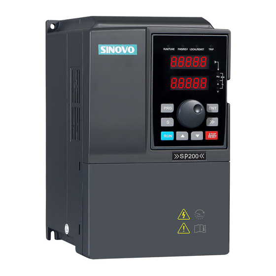
SP200 SERIES
PV PUMP CONTROLLER
User Manual
Advertisement
Table of Contents

Related Manuals for Sinovo SP200 Series


Summary of Contents for Sinovo SP200 Series
- Page 1 SP200 SERIES PV PUMP CONTROLLER User Manual SHENZHEN SINOVO ELECTRIC TECHNOLOGY CO.,LTD Add: 5th Floor,No.D Building,Huafeng International Robot Industry Park,Xixiang Street,Hangcheng Road,Baoan District,Shenzhen City 0755 29784870 ax: ( 0755 29784969 Tech suppor : 400-881-8689 Version: 2.0 http: //www.sinovo.cn...
-
Page 2: Preface
Thank you for purchasing the SP200 series PV Pump controller developed by our company. This manual introduce how to use SP200 series in correct manner. Please read it carefully before application, operation, maintenance and inspection. Please apply this series after fully understand the safety cautions of this products. -
Page 3: Table Of Contents
SP200 Manual Contents Contents Preface.........................01 Contents.......................02 Chapter 1 Safety and Cautions................05 Safety Definition.....................05 1.1 Safety Cautions....................06 1.2 Cautions......................08 Chapter 2 Basic principle...................11 2.1 Basic principle....................2.2 Functions......................Chapter 3 Product Information.................15 3.1 Inspection.. - Page 4 SP200 Manual Contents Chapter 6 Function Parameter Table...............41 F00 Basic Function Group..................42 F01 Startup and Stop Control.................42 F02 Motor parameter................... F03 Solar Water Pump Special Parameters............. F05 Input Terminal Group......
-
Page 6: Chapter 1 Safety And Cautions
Chapter Safety and Cautions Safety Definition Read this manual carefully so that you have a thorough understanding. Installation,commissioning or maintenance may be performed in conjunction with this chapter. Our company will assume no ability and responsibility for any injury or loss caused by improper operation. -
Page 7: Safety Cautions
SP200 Manual Chapter1 Safety and cautions 1.1 Safety Cautions Use Stage Safety Grade Precautions Do not install the equipment if you find water seepage, ª component missing or damage upon unpacking. Danger Do not install the equipment if the packing list does not ª... - Page 8 SP200 Manual Chapter1 Safety and cautions Use Stage Safety Grade Precautions Use a shielded cable for the encoder, and ensure that the ª Danger At wiring shielding layer is reliably grounded. Please confirm the peripheral equipment and cable converter ª is configured in this manual of the recommended model, all the configuration line in accordance with the connection method of the manual provides the correct wiring.
-
Page 9: Cautions
SP200 Manual Chapter1 Safety and cautions Use Stage Safety Grade Precautions ª Set and check the parameters again after the controller is After Danger replaced. Power-on 1.2 Cautions 1.2.1 Motor Insulation Test Perform the insulation test when the motor is used for the first time, or when it is reused after being stored for a long time, or in a regular check-up, in order to prevent the poor insulation of motor windings from damaging the controller during the insulation test. - Page 10 SP200 Manual Chapter1 Safety and cautions SP200 controller U V W Capacitor or voltage-sensitive resistor 1.2.7 Contactor at the I/O terminal of the controller When a contactor is installed between the input side of the controller and the power supply, the controller must not be started or stopped by switching the contactor on or off.
- Page 11 SP200 Manual Chapter1 Safety and cautions 1.2.12 Some Special Usages If writing that is not described in this manual, such as common DC bus is applied, cont- act the agent or Our company for technical support. 1.2.13 The Cautious of the controller Disposal The electrolytic capacitors on the main circuits and PCB may explore when they are burnt.
-
Page 12: Chapter 2 Basic Principle
Chapter Basic principle 2.1 Basic principle SP 200 solar pumping system can provide water for remote areas lacking of electricity or places where the electricity supply is unstable. PV pump controller can convert the DC power from solar panels to AC power so to drive various kinds of pumps.System enables continiously pumping when in good weather. - Page 13 SP200 Manual Chapter2 Basic principle C.SP200 PV pump controller F.Storage tank A.solar panels B.DC circuit braker E. well water D.pump level switch 2-1 SP200 PV pumping system SP200 PV pumping system is composed of following parts: A: Solar panels B DC circuit braker or disconnector C SP200 PV pump controller D Pump E well water level switch(optional)
-
Page 14: Functions
Note: Based on different models, SP200 input power could be 220v AC single power, or 380V AC 3 phase power. For more information, please contact SINOVO or certified agent. When the system is running by spare AC power, please check the DC power every 30 mins. - Page 15 SP200 Manual Chapter2 Basic principle Note: DC circuit switching and generator power switch installation are required and both switches should be mutually locked to prevent they were connected at the same time which lead to the solar panels and generator connect SP200 controller simultaneously. Please check if the design meets electrical specifications of relative country and area.
-
Page 16: Chapter 3 Product Information
Chapter Product Information 200 PV pump controller is adjustable speed motor controller designed in accordance with any IEC standard 3 phase asynchronous motor。 SP200 PV pumping system convert the high voltage DC power of solar array into AC power to drive an standard 3 phase asynchronous motor thus provide water for remote areas. -
Page 17: Inspection
SP200 Manual Chapter3 Product Information 3.1 Inspection Before using, please check the SP200 PV pump controller components firstly. Please make sure the components serial number is correct and if the product is damaged during shipping. 3.2 Instroductions and Feature SP200 PV Pump Controller monitor the system performance continiously and with integrated protection of multi-function pump system. -
Page 18: Naming Rules
SP200 Manual Chapter3 Product Information 3.4 Naming Rules In the model code contains the product information Users can find the code from the transducerand simple nameplate. Field Mark Content controller series Solar water pump controller Series second generation Series number 2: Three-phase 220V Voltage Level 4 Three-phase 380V... - Page 19 SP200 Manual Chapter3 Product Information SP200-4TXXX Input/output parameter Model SP200-4T-2.2 SP200-4T-3.7 SP200-4T-5.5 SP200-4T-7.5 PV array input parameter input voltage V ( ) DC 800V Min input voltage V ( ) DC 350V Recommended DC 500~600V voltage(mpp) Recommended 2.7 3.5 4.8~6.4 6.6~8.8 9~12 PV power(Kw)
- Page 20 SP200 Manual Chapter3 Product Information Model SP200-4T-30 SP200-4T-37 SP200-4T-45 SP200-4T-55 PV array input parameter input voltage V ( ) DC 800V Min input voltage V ( ) DC 350V Recommended DC 500~600V voltage( mpp) Recommended 36~48 44~59.2 54~72 66~88 PV power(Kw) Spare AC generator 3-phase AC 380/400/415/440V(+15%) Input voltage(V)...
- Page 21 SP200 Manual Chapter3 Product Information Model SP200-4T-160 SP200-4T-200 SP200-4T-220 SP200-4T-250 PV array input parameter input voltage V ( ) DC 800V Min input voltage V ( ) DC 350V Recommended DC 500~600V voltage( mpp) Recommended 300~400 192~256 240~320 264~352 PV power(Kw) Spare AC generator (...
-
Page 22: Nameplate
OUTPUT: AC3PH 380V 50/60Hz 17A frequency and current Bar code S/N: FDLAGCA1A042 SHENZHEN SINOVO ELECTRIC TECHNOLOGIES CO.,LTD. MADE IN CHINA Figure 3-2 Name Designation Rules 3.7 SP200 PV Pump Controller Size Ø 7.5KW Less than 7.5KW Controller installation dimensions and installation size... - Page 23 SP200 Manual Chapter3 Product Information 3.7.1 Installation Hole Size iameter H1(mm) W1(mm) H(mm) W(mm) D(mm) Controller Model (mm) SP200-2 S -0.7 -2 -1.5 SP200 S Ø5 -2 -2.2 SP200 S SP200-2T-0.7 SP200-2T-1.5 Ø5 SP200-2T-2.2 SP200-4T-0.7 SP200-4T-1.5 Ø5 SP200-4T-2.2 SP200-4T-4.0 Ø5 SP200-4T-5.5 Ø5 SP200-4T-7.5...
- Page 24 SP200 Manual Chapter3 Product Information 3.7.2 External Keypad Installation Dimensions 79.00 74.80 Figure 3-3 Keypad Installation dimensions Figure 3-4 Figure 3-5 Opening dimension diagram Opening dimension diagram for keypad with base for keypad without base -23-...
- Page 25 -24-...
-
Page 26: Chapter 4 Mechanical And Electrical Installation
Chapter Mechanical and Electrical Installation Danger Only those who are trained and qualified professionals can operate the work described ª in this chapter. Please operate according to the section of "pay attention to security matters", failure to these may cause personal injury or damage to equipment. Connect the input power lines tightly and permanently. -
Page 27: Controller Installation And Operation Environment
SP200 Manual Chapter4 Mechanical and Electrical Installation Note Lift the controller by its base other than the keypad or the cover. The dropping of the ª main part may cause personal injury. ª Install the equipment on incombustible objects such as metal, and keep it away from ª... -
Page 28: Controller Installation Spacing
SP200 Manual Chapter4 Mechanical and Electrical Installation 4.2 Controller Installation Spacing Fan exhaust More than 100mm More than 50mm More than 100mm Figure 4-1 Installation distance Figure 4-2 Installation of multiple controller Upper row and lower row installation for two controller, A guide plate should be added between the two controller. -
Page 29: Wiring
SP200 Manual Chapter4 Mechanical and Electrical Installation 4.4 Wiring Danger Only qualified electricians are allowed to operate on the safe running of the controller. ª Never carry out any insulation or voltage withstand tests on the cables connecting with ª the controller. - Page 30 SP200 Manual Chapter4 Mechanical and Electrical Installation 4.4.1 Typical Wiring Diagram A.solar panels SP200 DC310V /540V MCCB Main circuit 3-phase380V/480V Input power 50/60Hz +24V Keypad interface DISP1 OPEN Digital input 1 Expansion card interface Digital input 2 Digital input 3 Digital input 4 485 communication interface OFF ON...
- Page 31 SP200 Manual Chapter4 Mechanical and Electrical Installation 4.4.2 Terminal Diagram 4.4.2.1 Main Circuit Terminal Ground Motor DC input 3-phase input power Figure 4-5 Suitable for SP200-4T-22G/30P or less than 22KW machines Shorting bar Motor Ground 3-phase input power DC Reactor DC input Figure 4-6 Suitable for SP200-4T-30G/37P or more than 37KW machines The main circuit terminals function description is as follows:...
- Page 32 SP200 Manual Chapter4 Mechanical and Electrical Installation 4.4.3 Terminal Diagram For solar pumping system, Dual DC circuit breaker must be installed between PV array and SP200 PV Pump Controller.Connect the cable of the bottom part of dual DC breaker marked as "+" and "-" to SP200 PV Pump Controller wiring terminals "+" and "-". Note: R、...
- Page 33 SP200 Manual Chapter4 Mechanical and Electrical Installation 4.4.7 Well low water level probe wire (optional) To avoid the damage of the pump due to pumping in dry condition, well probe can be connected to the control terminals of SP200 PV Pump Controller to detect the well water level, the length of the well probe should not exceeds 50m.If there is no well probe to detect the water level, please keep the 2 terminals of the controller shorted( It is shorted before leaving factory).
- Page 34 SP200 Manual Chapter4 Mechanical and Electrical Installation Floating ball switch Up: OFF Down:ON Noramal: ON If the cable is shielding wire only need to be grounded here 4.4.9 Electrical Conduit application When the system is installed in outdoor, electrical conduit is required to use to protect the outdoor cable from the influences of weather, human activity, chewing animals.
- Page 35 -34-...
-
Page 36: Chapter 5 Operation
Chapter Operation -35-... -
Page 37: Operation Panel Description
SP200 Manual Chapter5 Operation 5.1 Operation Panel Description 5.1.1 Panel Diagram Figure 5-1 SP200 KBA keypad diagram 2 Button Function Descriptions Name Instructions LED off means that the controller is in the stopping state; LED blinking means the controller is in the parameter RUN/TUNE autotuning state;... - Page 38 SP200 Manual Chapter5 Operation Name Instructions It represents the current display of the Keypad Frequency unit Current unit Unit indicator Voltage unit Speed unit Percentage 5-figure LED display displays various monitoring data and alarm code such as set frequency and output frequency. Correspo- Correspo- Correspo-...
-
Page 39: Operation Procedure
SP200 Manual Chapter5 Operation Name Instructions The key is used to operate on the controller in key Run key operation mode This key is used to stop in running state; This key Stop/Reset is used to reset all control modes in the fault alarm state.. - Page 40 Figure 5-3 Modifying parameters diagram 5.2.2 Password Setting SP200 series controller provide password protection function to users. Set F07.00 to gain the password and the password protection becomes valid instantly after quitting from the function code editing state. Press "PRG" again to the function code editing state,“0.0.0.0.0”will be displayed.
-
Page 41: Commissioning Process
SP200 Manual Chapter5 Operation 5.3 Commissioning Process Check and confirm the wiring is correct. 2: Using high a megger to test the insulation of the motor and cable if needed. 3: Use a multimeter to test whether the open circuit voltage of the DC switch solar modules meet the requirements. -
Page 42: Chapter 6 Function Parameter Table
Chapter Function Parameter Table User-defined Parameters ○ “ ”means the set value of the parameter can be modified on stop and running state; ◎ “ ”means the set value of the parameter can not be modified on the running state; “●”means the value of the parameter is the real detection value which can not be modified. -
Page 43: F00 Basic Function Group
SP200 Manual Chapter6 Function Parameter Table Function Default Modifi- Setup range Name code Value cation Group F00 Basic Function Group 0: Keypad run command channel(LED is OFF) 1: Terminal command channel / Keypad STOP disabled(LED is ON) 2: Terminal command channel / Keypad STOP )... -
Page 44: F05 Input Terminal Group
SP200 Manual Chapter6 Function Parameter Table Function Default Modifi- Setup range Name code Value cation The lowest operating ◎ F03.08 0~6553.5s 10.0s frequency of water outlet 120.0s ◎ F03.09 Wake detection time 1 0~F3.11s Wake up voltage ◎ F03.10 0~6553.5V 10.0V detected increases in 600.0s... - Page 45 SP200 Manual Chapter6 Function Parameter Table Function Default Modifi- Setup range Name code Value cation The 2 times ---- ● F07.20 before fault type The 3 times ---- ● F07.21 before fault type See Chapter Seven 7.1 Fault Information and Troubleshooting The 4 times ---- ●...
- Page 46 SP200 Manual Chapter6 Function Parameter Table Function Default Modifi- Setup range Name code Value cation Ramp reference frequency ---- ● F07.41 0.0V at previous 2 fault Output voltage ---- ● F07.42 0.0℃ at previous 2 faults Output current ---- ● F07.43 at previous 2 fault Bus voltage...
- Page 47 SP200 Manual Chapter6 Function Parameter Table Warning: Do not touch any part inside the SP200 PV Pump controller when power on.If you want to use the controller in other areas, please disconnect all the power supply, and wait for 5 minutes before operate.In general, for the selection of SP200 PV pump controller, the controller and the pump power can be matched.However, controller Please enlarge a document if you are driving a submersible pump.It's uneccessary to enlarge while driving a ground pump.
-
Page 48: Chapter 7 Troubleshooting
Chapter Troubleshooting SP200 PV pump controller attempts to drive water pumps to lift water even in severe weather conditions. In order to ensure reliable service life, it must to be protected all system components stay away from some factors that could damage the device. When there is a bad situation, if necessary, the controller will reduce the output, continue to water delivery as much as possible, and close in extreme cases. -
Page 49: Fault Instruction And Solution
SP200 Manual Chapter7 Troubleshooting 7.1 Fault Instruction and Solution No. Code Fault Cause Solution IGBT U phase ♦ The acceleration is too fast . ♦ Increase Acc time. E.out 1 protection ♦ Change the power unit. ♦ There is damage to the intern- ♦... - Page 50 SP200 Manual Chapter7 Troubleshooting No. Code Fault Cause Solution ♦ Ambient temperature is too high. IGBT ♦ The time of overload running is E,OH2 ♦ Check input power overheated too long ♦ SI external fault input terminals ♦ Check input power E.EF External fault action.
- Page 51 SP200 Manual Chapter7 Troubleshooting No. Code Fault Cause Solution ♦ The controller will report the over- ♦ Check the load and the Electronic load pre-alarm according to the E.oL3 overload fault overload pre-alarm point. set value. ♦ Check the Keypad wires ♦...
-
Page 52: Common Faults And Solutions
SP200 Manual Chapter7 Troubleshooting No. Code Fault Cause Solution ♦ Closed loop control, encoder ♦ Check encoder connection, Encoder disconnection, damage or conn- E.Ecd2 reverse fault adjust wiring. ect fault. ♦ Check the motor and main- ♦ Motor long-term overload running tain. -
Page 53: Controller Overcurrent, Overload Fault (Oc1/2/3/Ol1/2)
SP200 Manual Chapter7 Troubleshooting 2. Power on operation panel display “CE”: Inspect whether the keypad and master control board wiring is normal once they appear fault. 3. Power supply air switch trips off when power on: 1) Inspect whether the ground terminal E is grounded. Please solve the problem. 2) Inspect whether the input power supply is grounded or short circuit. -
Page 54: Chapter 8 Maintenance
Chapter Maintenance Danger ª Maintenance must be performed according to designated maintenance methods. ª Maintenance, inspection and replacement of parts must be performed only by certified person. ª After turning off the main circuit power supply, wait for 10 minutes before maintenance or inspection. -
Page 55: Controller
SP200 Manual Chapter8 Maintenance 8.1 Controller 8.1.1 Controller Controller belong to electric product, when operate, it will heating. Therefore, it is nece- ssary for daily and periodic maintenance and clear. Routine cleaning involves: 1. Keep the controller clean all the time. 2. - Page 56 SP200 Manual Chapter8 Maintenance Component Service life 2~3 years Electrolytic 4~5 years capacitor Note: The standard replace time is the following using time, users can confirm the replace use age comply to the running time. ◆ Environment temperature: The annual average temperature is about 30 degrees. ◆...
-
Page 57: Pump
SP200 Manual Chapter8 Maintenance Reasonable repair expense will be charged for the damages due to the following causes: a. Improper operation without following the instructions. b. Fire, flood or abnormal voltage. c. Using the controller for non-recommended function. 4. The maintenance fee is charged according to Our company’s uniform standard. If there is an agreement, the agreement prevails. -
Page 58: Chapter 9 Spare Ac Power Use
Chapter Spare AC Power Use In order to ensure continuous supply water, user can manual switch the SP200 PV pumping system to the standby AC power supply when the light is insufficient or rainy weather. When switching, DC and AC power interlock need to be ensured. Alternate AC power not only can be local network but also can be diesel generator (Please refer to 2.4.3 input and output parameter table). - Page 59 SP200 Manual Chapter9 Spare AC Power Use Three phase 380VAC Alternate AC power supply, for example, wiring diagram such as following: no function Spare AC input, Pump grounding AC DC cannot When reverse, input at the change any same time two cables Low water level probe Remote floating...
- Page 60 . † If there is any problem during the service , please contact the agent of our company or our company directly . SHENZHEN SINOVO ELECTRIC TECHNOLOGIES CO.,LTD. Service Department Add: 5th Floor,No.D Building ,Huafeng International Robot Industry Park, Xixiang Street ,Hangcheng Road, Baoan District, Shenzhen City :...
- Page 61 Product Warranty Card Add. of corporation: Name of corporation: Contact person: Customer information P.C.: Tel.: Product model: Body bar code: Product information Name of agent: (maintenance time and content): Failure information Maintenance personnel: -60-...
Need help?
Do you have a question about the SP200 Series and is the answer not in the manual?
Questions and answers