Table of Contents
Advertisement
Advertisement
Table of Contents

Related Manuals for DentalEZ RAM VAC Osprey


Summary of Contents for DentalEZ RAM VAC Osprey
- Page 1 SPREY Osprey Dental Compressor User Manual...
-
Page 2: Table Of Contents
Section V Care Cleaning ............25 Maintenance ............ 25 Section VI User Service Information Service Instruction ........... 31 Disposal of Equipment ........31 Section VII Parts Lists/Diagrams ..... 33 EMC Information ..........35 Limited Warranty ..........37 www.DentalEZ.com 866-DTE-INFO PN: 1045DOC_E... - Page 3 Osprey Compressor www.DentalEZ.com 866-DTE-INFO PN: 1045DOC_E...
-
Page 4: Section I Introduction
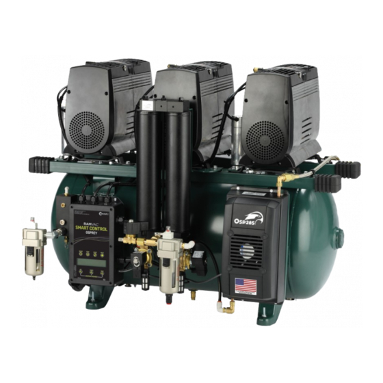
Filter Filter Valve Unloader Safety Valve Electrical Coalescing Valve Filter Coalescing Safety Filter Valve Smart Control Heat Exchanger Heat Exchanger & Fan & Fan Figure 1. Main components of the Osprey compressor (basic and smart models) www.DentalEZ.com 866-DTE-INFO PN: 1045DOC_E... -
Page 5: Compressor Features
• Optional sound cover lowers decibel ratings by 6 to 8 decibels. It is available for all Osprey models and is simple to install. www.DentalEZ.com 866-DTE-INFO PN: 1045DOC_E... -
Page 6: Specifi Cations
(-29°C to 74°C) • Relative humidity range: 0% to 95% Operation • Temperature range: 35°F to 100°F (2°C to 38°C) • Relative humidity range: 0% to 95% Indoor Use • Altitude up to 9,000 ft (2,743 m) www.DentalEZ.com 866-DTE-INFO PN: 1045DOC_E... -
Page 7: Classifi Cations
= Electromagnetic Radiation = Box Must Remain Upright = Do Not Place Box on Unlevel Surface = Do Not Stack Box = Box Contents Safe Temperature Range 74°C (165°F) -29°C (-20°F) = Box Contents Safe Humidity Range www.DentalEZ.com 866-DTE-INFO PN: 1045DOC_E... -
Page 8: Safety Precautions
• Danger of fi re or explosion when using power. Overheating could result. fl ammable substances. • Connect only equipment suitable for listed • Never leave children unattended when maximum pressure of the compressor. compressor is in use. www.DentalEZ.com 866-DTE-INFO PN: 1045DOC_E... - Page 9 • An air leakage test should be conducted on the facility air system to ensure no air leaks are present. Excessive air leakage will impact the performance and life expectancy of your compressor. www.DentalEZ.com 866-DTE-INFO PN: 1045DOC_E...
-
Page 10: Section Ii Preinstallation Packaging
Open the valve after Rubber Grips (2) Rubber Grips (2) installation. Figure 2. Rubber grips (4) NOTE: LIfting the compressor assembly by any other part or location could result in damage to the compressor. www.DentalEZ.com 866-DTE-INFO PN: 1045DOC_E... -
Page 11: Placement
• Locate the compressor on a level hard surface capable of supporting the compressor weight. If a level surface is not available, the compressor is equipped with height adjustable feet to level the device. Install four adjustable rubber feet www.DentalEZ.com 866-DTE-INFO PN: 1045DOC_E... -
Page 12: Site Requirements
• Qualifi ed personnel must install a dedicated electrical circuit of suff icient capacity. See www.DentalEZ.com 866-DTE-INFO PN: 1045DOC_E... - Page 13 Osprey Compressor www.DentalEZ.com 866-DTE-INFO PN: 1045DOC_E...
-
Page 14: Section Iii Installation
Parts Included Foot Flanged • Foot (4 Pieces) • Flanged Nut Figure 4. Block compressor tank to install feet (4 Pieces) Figure 3. Feet kit parts www.DentalEZ.com 866-DTE-INFO PN: 1045DOC_E... -
Page 15: Filter Drain Kit
Parts Included After adjusting the feet, tighten the fl anged nut Elbow Drain Hose Fitting with a 1/2" wrench to lock the foot into position. • Drain Hose • Elbow Fitting Figure 6. Filter drain kit parts www.DentalEZ.com 866-DTE-INFO PN: 1045DOC_E... - Page 16 3. If for some reason the fi tting or hose needs to be released from the connection, depressing the colored plastic ring (while gently pulling on the hose or fi tting) releases the hose or fi tting from the connection (Figure 7). www.DentalEZ.com 866-DTE-INFO PN: 1045DOC_E...
-
Page 17: Low Voltage Wiring Kit
Wire Nuts Connector for Basic for Smart Controls Controls Basic Smart Control Control Figure 8. Low voltage wiring kit parts Figure 9. Basic and smart control electric panels www.DentalEZ.com 866-DTE-INFO PN: 1045DOC_E... -
Page 18: Low Voltage Remote Switching
• Schedule mode automatically turns on or off all devices by a saved user defi ned weekly schedule. • Master Shutdown turns off the entire utility room when activated. • Non-illuminated switches provide no indication for system status. www.DentalEZ.com 866-DTE-INFO PN: 1045DOC_E... - Page 19 Low Voltage Switch Wires Alternative Switching Black Toggle Switch or Other Non- C2 Control Purple Illuminated Basic Terminals Black Switch (Option) Purple +24V DC (Purple) Air Switch +24V DC (Red) Air Light DC Common (Black) Common www.DentalEZ.com 866-DTE-INFO PN: 1045DOC_E...
-
Page 20: Outlet Plumbing Kit
Under no circumstances should it be supplied or considered as medical/breathing air for a patient. Parts Included • Final Filter • Facility Supply Hose • Fittings • Thread Sealer Figure 10. Outlet plumbing kit parts www.DentalEZ.com 866-DTE-INFO PN: 1045DOC_E... - Page 21 Tighten any joints that may be leaking. • Check the facility plumbing for leaks, either by inspection or by completing a pressure decay test. Repair any leaks in the facility plumbing. Figure 11. Filter mounting options www.DentalEZ.com 866-DTE-INFO PN: 1045DOC_E...
-
Page 22: Section Iv Operation
C2 control, which runs the motors on demand. 6. Turn the shut-off valve to OPEN. Pressure is factory set from 85 to 115 PSI and is not adjustable. www.DentalEZ.com 866-DTE-INFO PN: 1045DOC_E... -
Page 23: C2 Control Display Screen
Display Remote Switch Connection Communication Cable Cat 6 Motor Disable Control Buttons (4) Starts Unit Stops Unit from Running Resets Alarms and Maintenance Timer Toggles Screens in Display Figure 12. Osprey compressor C2 smart control panel www.DentalEZ.com 866-DTE-INFO PN: 1045DOC_E... - Page 24 Factory set to count down from 700 hours. Alert given SCREEN 8 when reaches zero. Reset counter with RESET button SCREEN 9 Factory set to count down from 3,500 hours. Alert given when reaches zero. Reset counter with RESET button BOOT UP Model number. www.DentalEZ.com 866-DTE-INFO PN: 1045DOC_E...
- Page 25 Lost connectivity with Owl Hub. Check cable and connections. System hours counted only when unit is activel running. MAINTENANCE RESET button for 5 seconds. SCREEN Perform dryer maintenance and reset timer by holding RESET button for 5 seconds. www.DentalEZ.com 866-DTE-INFO PN: 1045DOC_E...
-
Page 26: Enable High-Pressure Mode
IN HI PRESS MODE OWL COM DISABLED. This indicates that the On Wall Figure 16. Press NEXT button Logic (OWL) Smart Hub is in high-pressure mode and will have limited functionality with the compressor (Figure 16). www.DentalEZ.com 866-DTE-INFO PN: 1045DOC_E... - Page 27 Osprey Compressor www.DentalEZ.com 866-DTE-INFO PN: 1045DOC_E...
-
Page 28: Section V Care Cleaning
Scan QR code to view online • Follow the recommended Preventive Osprey Maintenance Video Maintenance Schedule. www.DentalEZ.com/CompressorMaintenanceVideo • Check the coalescing and particulate fi lters indicator every month (see Checking Moisture Indicator and Checking Filter Element Service Indicator in this section). - Page 29 Intake maintenance screen on the C2 control and Filter pressing the RESET button. Osprey basic models: There is no maintenance alarm. Figure 17. Remove intake fi lter cap and replace intake fi lter www.DentalEZ.com 866-DTE-INFO PN: 1045DOC_E...
- Page 30 9. Return compressor to service. Filter Bowl .3 Micron Filter Filter Bowl .01 Micron Filter Figure 19. Remove intake fi lter cap and replace fi lter Figure 18. Remove fi lter bowl and replace fi lter www.DentalEZ.com 866-DTE-INFO PN: 1045DOC_E...
- Page 31 6. Return compressor to service. Hearing protection is recommended during service of this device. Tank Petcock Safety Valve Ring Figure 20. Open tank petcock Figure 21. Pull ring on safety valve www.DentalEZ.com 866-DTE-INFO PN: 1045DOC_E...
- Page 32 3. Open the petcock to drain any air in the tank. NOTE: Replace an element annually, even if the red DO NOT pull the pressure relief valve to depressurize indicator does not reach the top. the air system. www.DentalEZ.com 866-DTE-INFO PN: 1045DOC_E...
- Page 33 Osprey Compressor www.DentalEZ.com 866-DTE-INFO PN: 1045DOC_E...
-
Page 34: Section Vi User Service Information
Section VI User Service Information Service Instruction Disposal of Equipment Disposal and Decommissioning of If the area of concern is not addressed in this manual, contact your local DentalEZ full-service DentalEZ Products dealership at 866-DTE-INFO (see Limited NOTE: All local regulatory requirements for Warranty). - Page 35 Osprey Compressor www.DentalEZ.com 866-DTE-INFO PN: 1045DOC_E...
-
Page 36: Section Vii Parts Lists/Diagrams
Section VII Parts Lists/Diagrams DentalEZ Parts Online To order parts online, visit www.dentalezparts.com or scan QR code with smartphone. www.DentalEZ.com 866-DTE-INFO PN: 1045DOC_E... - Page 37 Osprey Compressor www.DentalEZ.com 866-DTE-INFO PN: 1045DOC_E...
-
Page 38: Emc Information
Power Frequency (50/60 Hz) 3 A/m Not applicable levels characteristic of a typical location in a typical Magnetic Field IEC 61000-4-8 commercial or hospital environment. NOTE: Ut is the AC mains voltage prior to application of the test level. www.DentalEZ.com 866-DTE-INFO PN: 1045DOC_E... - Page 39 NOTE 1: At 80 MHz and 800 MHz, the separation distance for the higher frequency range applies. NOTE 2: These guidelines may not apply in all situations. Electromagnetic propagation is aff ected by absorption and refl ection from structures, objects and people. www.DentalEZ.com 866-DTE-INFO PN: 1045DOC_E...
-
Page 40: Limited Warranty
Dental Compressor DentalEZ® and its employees are proud of the products we provide to the dental community. We stand behind these products with a warranty against defects in material and workmanship as provided below and have our own in-house repair facility to service our products. - Page 41 2500 Highway 31 South Bay Minette, Alabama 36507 866-DTE-INFO www.dentalez.com © DentalEZ® Alabama, Inc. Printed in USA PN: 1045DOC_E April, 2019...
Need help?
Do you have a question about the RAM VAC Osprey and is the answer not in the manual?
Questions and answers