Table of Contents
Advertisement
Quick Links
Advertisement
Table of Contents

Related Manuals for AMI 3010BR


Summary of Contents for AMI 3010BR
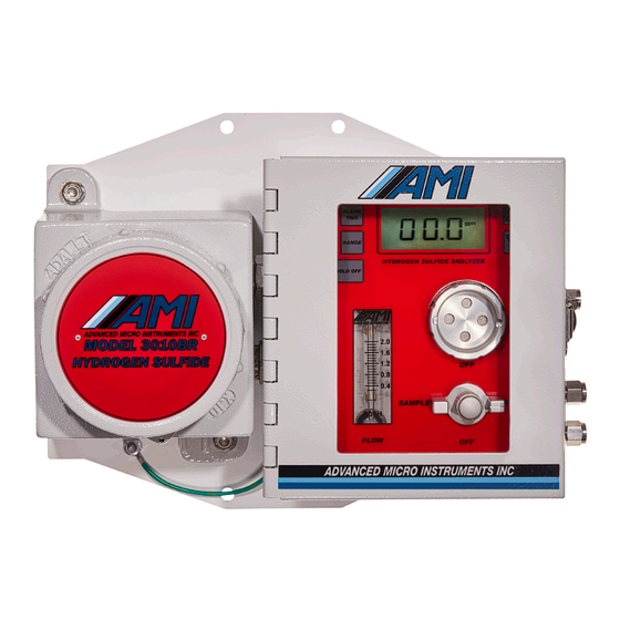
- Page 1 S Analyzer Manual Model 3010BR AMI, Costa Mesa, CA...
-
Page 2: Table Of Contents
Contents Preface Thank you! WARNING! Caution Address Model 3010BR Hydrogen sulfide Analyzer Introduction Features: Analyzer description: Sensor Warranty: Instrument Warranty: Hydrogen sulfide toxicity: Important: Points to consider first! Installation and Operation Installation. Location: Safety Considerations: Installation Procedure Initial Calibration: Front Panel Settings and Adjustments... - Page 3 Changing the output from 1-5 VDC to 4-20mA (or vice versa) Output Selection: Flow Control Advanced Features and Communications Communication Program: Maintenance and troubleshooting Maintenance: Periodic Calibration: Sensor Replacement: Sensor replacement cautions: Sensor replacement procedure: Specifications and Disclaimer Specifications Disclaimer Contents ii AMI Analyzer Manual...
-
Page 4: Preface
Please verify that the analyzer was not damaged in transit. If so please contact the shipper as well as AMI. WARNING! HYDROGEN SULFIDE IS EXTREMELY TOXIC AND CAN BE LETHAL! Read this manual carefully before using this instrument. -
Page 5: Model 3010Br Hydrogen Sulfide Analyzer
Model 3010BR Hydrogen sulfide Analyzer Introduction Using the same advanced engineering perfected in the 2010BR trace oxygen analyzer, AMI has produced an equally effective hydrogen sulfide analyzer. Instead of having to use clumsy, unreliable lead acetate tape, or alternatively very expensive and delicate laser diode analyzers, AMI has applied a unique electrochemical sensor to a modified version of the proven platform of the 2010BR to produce an equally effective hydrogen sulfide analyzer. -
Page 6: Analyzer Description
(which slows the response of this kind of analyzer). AMI uses a version of the patented “Cell block”, a machined block of nickel-plated aluminum that integrates all of these functions in one compact, and reliable package. -
Page 7: Sensor Warranty
The sensor has an expected life of three years, and it is warranted to operate for a period of one year on a pro-rated basis. If the sensor ceases to operate correctly before this time has elapsed, contact AMI for a return authorization for evaluation. - Page 8 800 ppm is the lethal concentration for 50% of humans for 5 minutes exposure(LC50). Concentrations over 1000 ppm cause immediate collapse with loss of breathing, even after inhalation of a single breath. AMI Analyzer Manual Model 3010BR Hydrogen sulfide Analyzer ...
-
Page 9: Important
Sample conditions – if your sample is hot and wet, you will need to keep water from condensing in the sample line or analyzer. The AMI demister brings hot and wet gases back to ambient temperature and allows the condensation and entrained liquids to fall back into the pipeline (no draining is necessary, unlike a coalescing filter which requires routine maintenance). -
Page 10: Installation And Operation
It should be mounted at a suitable viewing level. Refer to the drawing (figure 1) showing the analyzer dimensions. EXPLOSION-PROOF SEALS ARE REQUIRED ON THE POWER AND SIGNAL CONDULET ENTRIES, whether the area classification is Division 1 or Division 2. AMI Analyzer Manual Installation and Operation ... -
Page 11: Safety Considerations
There is an RS485 connection running ModBus available from the explosion-proof section. This may be wired up permanently. There is also a USB port in the explosion-proof section that may be used occasionally by removing the explosion-proof cap. If so, the area MUST be declassified first. AMI Analyzer Manual Installation and Operation ... -
Page 12: Installation Procedure
Don’t allow liquid water to enter the analyzer! This may mean that you have to cool the sample and drop out water before it gets into the analyzer. AMI Analyzer Manual Installation and Operation ... - Page 13 They are by default programmed to close on alarm above set point (though this can be changed with the user interface). They can handle 5A at 24DC or 117VAC. AMI Analyzer Manual Installation and Operation ...
- Page 14 For details on the front panel controls see the chapter in this manual called “Operation”. 7. If it is desired to use the advanced functions available, purchase the AMI user interface program and the custom RS-232 cable, and refer to the chapter in the manual called “Advanced Features and Communications”.
-
Page 15: Initial Calibration
NEMA 4 box. 3. Set the regulator pressure to 10psig. 4. We recommend using the special AMI supplied span gas tubing with O ring sealed fittings so as to prevent fitting damage to the span port. 5. Confirm all fittings are tight. - Page 16 Do not leave the gas cylinder on when you are not spanning the analyzer, as not only may you drain the cylinder but any leak will contaminate the area and can be dangerous. Turn the bottle off with the cylinder valve. AMI Analyzer Manual Installation and Operation ...
-
Page 17: Front Panel Settings And Adjustments
(only the Alarm hold off button performs a function, though other buttons will show settings but won’t allow them to be changed). If the front panel controls don’t seem to work, use the AMI User Interface to change the security settings. -
Page 18: Output Ranges
If the range changes back again after you let go, the security level must be set to full or span only security. In this case change the security level with the laptop and the AMI User Interface program. Alarm Set Points The alarm set points can be viewed and changed (if security allows) from the front panel. -
Page 19: Alarm Hold Off
View the Span Factor: The model 3010BR has a “Span Factor” feature. It can be displayed on the LCD by pressing the UP arrow by itself (when the analyzer is in normal operation, meaning not in a function such as spanning or setting the alarms). -
Page 20: Changing The Output From 1-5 Vdc To 4-20Ma (Or Vice Versa)
10,000 Ohm load. Either will saturate at more than 125% of the nominal full scale range. Using AMI software you can set the output to 4mA, 12mA and 20mA(or 1V, 3V and 5V), and adjust the internal settings to calibrate these values so as to get the most accurate possible transfer of information to a recording or computing device. -
Page 21: Output Selection
It is in the left hand position for 4-20mA, and the right hand position for 1-5V. If you switch between the two options the internal calibration will be fairly close but not perfect, so it may be necessary to use the AMI User Interface to make the output exact. AMI Analyzer Manual... -
Page 22: Flow Control
Flow meter – Shows the sample or span flow rate in the range of 0 to 2 SCFH. The flow should generally be set at 1 SCFH. AMI Analyzer Manual Installation and Operation ... - Page 23 – Located on the right side of the NEMA 4 box. They all use ¼” Swagelok fittings, though if the span connection if likely to be made and broken may times, it is best to use the AMI provided sample tubing with O ring style fittings. AMI Analyzer Manual...
-
Page 24: Advanced Features And Communications
Advanced Features and Communications Communication Program: The analyzer supports both the industry-standard ModBus protocol running on an RS485 loop, and the AMI User Interface software connected via a USB port. If the USB connection is detected the ModBus connection will be disabled. -
Page 25: Maintenance And Troubleshooting
Maintenance and troubleshooting Maintenance: The model 3010BR is virtually maintenance free other than for periodic calibration and occasional sensor replacement. Periodic Calibration: The analyzer should be calibrated about once every month to obtain the best accuracy. The sensor typically declines in sensitivity by less than 1% of full scale per month, so a monthly calibration is usually satisfactory. - Page 26 Figure 7. Inserting sensor in cell block AMI Analyzer Manual Maintenance and troubleshooting ...
-
Page 27: Sensor Replacement Procedure
When it gets up to 1000 the sensor will have to be replaced. 18. Rotate the valve back to the Sample position. 19. Readjust the flow rate to 1 SCFH if necessary. AMI Analyzer Manual Maintenance and troubleshooting ... -
Page 28: Specifications And Disclaimer
Although every effort has been made to assure that the AMI analyzers meet all their performance specifications, AMI takes no responsibility for any losses incurred by reason of the failure of its analyzers or associated components. AMI’s obligation is expressly limited to the analyzer itself. - Page 29 Class I, Division 1, Groups B, C and D: Series 2010BR and 210BR Oxygen Analyzers and series 3010BR Hydrogen Sulfide Analyzers, input rated 117Vac, 0.5A max, 50/60Hz or 12-24VDC, 1.7A max or 12-24VDC, 0.1A max; with output rated 1-5V or 4- 20mA;...
- Page 30 Certificate: 1905645 Master Contract: 227773 Project: 70159520 Date Issued: November 28, 2017 APPLICABLE REQUIREMENTS CSA C22.2 No 0-10 General Requirements – Canadian Electrical Code, Part II – Tenth Edition CSA C22.2 No 30-M1986 (R 2007) Explosion-Proof Enclosures for Use in Class I Hazardous Locations Industrial Products –...
Need help?
Do you have a question about the 3010BR and is the answer not in the manual?
Questions and answers