Table of Contents
Advertisement
Advertisement
Table of Contents

Subscribe to Our Youtube Channel
Related Manuals for Merging Anubis


Summary of Contents for Merging Anubis
- Page 1 USER MANUAL V23.05.2019...
-
Page 3: Table Of Contents
Contents Thank you for purchasing MERGING+ANUBIS ................... 5 Important Safety and Installation Instructions ................... 6 Product Regulatory Compliance ........................8 MERGING+ANUBIS Warranty Information....................10 INTRODUCTION .............................. 11 Environmentally Friendly by Design ....................... 11 Package Content ............................11 OVERVIEW ..............................12 MERGING+ANUBIS VARIANTS AND KEY FEATURES ................ - Page 4 Bass Management Signal flow ......................51 INFO Settings .............................. 58 DEBUG Settings ............................58 EXIT Settings .............................. 59 ANUBIS MONITOR MISSION CONTROL ....................60 Sources vs. Monitors Fundamentals ..................... 62 Different Monitor types ..........................63 MONITOR PAGE ............................65 METERS PAGE ............................73 ANUBIS USE CASES ............................
-
Page 5: Thank You For Purchasing Merging+Anubis
Thank you for purchasing MERGING+ANUBIS This manual is intended to take you through the setup and installation of the MERGING+ANUBIS. We encourage you to familiarize yourself with the features, applications, and connection procedures before setting up your MERGING+ANUBIS. To ensure the safe operation of your Anubis please read the instructions, important safety... -
Page 6: Important Safety And Installation Instructions
Important Safety and Installation Instructions INSTRUCTIONS PERTAINING TO RISK OF FIRE, ELECTRIC SHOCK, OR INJURY TO PERSONS WARNING – when using electrical products, basic precautions should be followed, including the following: 1. Before using this product, read all of the safety and installation instructions and the explanation of graphic symbols. 2. - Page 7 Merging Technologies hardware and or software or for any defect in the hardware software or documentation.
-
Page 8: Product Regulatory Compliance
Product Regulatory Compliance Product Safety and EMC Compliance Merging Technologies ANUBIS is designed, tested and verified to comply with the following Safety & EMC regulations FCC – Radiated and Conducted Emissions (USA). CFR 47 Part 15 – Radiated and Conducted Emissions (Canada). - Page 9 Detailed specifications of the tested and certified product are shown in the following Test Report: Test report Ref No: 16'835 Issued Date: May 2019 by Schurter EMC SA The CE label is affixed on the bottom of the Anubis unit as per below: Date May 1 2019...
-
Page 10: Merging+Anubis Warranty Information
Merging Technologies, Inc. extends this Limited Warranty to the original purchaser. In the event of a defect or failure to confirm to this Limited warranty, Merging Technologies, Inc. will repair or replace the product without charge within sixty (60) days. In order to make a claim under this limited warranty, the purchaser must notify Merging Technologies, Inc. -
Page 11: Introduction
Environmentally Friendly by Design The MERGING+ANUBIS products have been carefully designed in order to keep power consumption to a strict minimum. Merging Technologies believes in a sustainable future and takes appropriate measures at all phases of a product's design and manufacture to avoid wasting energy. -
Page 12: Overview
Merging Technologies in analogue and digital, networked audio and DSP technology. More significantly, it offers unique features to any engineer or musician looking for a compact AD/DA unit with the quality you would expect from Merging, and a fully featured monitor controller that integrates with any DAW. - Page 13 Two exceptional high-power headphone amps with dedicated DACs ▪ Mute switch for any outputs ▪ The remote allows control of volume level and source selection of any Merging RAVENNA ▪ Device on the network In the Box and Expandable I/O through Hapi, Horus or any RAVENNA/AES67 devices ▪...
- Page 14 Built-in talkback microphone for communication and recording, possibility for 2 ▪ independent Talkbacks 5 Save/Recall Internal Presets and unlimited external Presets Save/Recall. ▪ Mic/Pre DAW remote control ▪ Standalone operations. Anubis can serve as a multi-channel analog converter or ▪ headphone amp when disconnected from the computer.
-
Page 15: About Ravenna
Booting up between missions completely changes the user interface and the function of Anubis. Plug-ins will be released to aid whatever workflow is required. Your investment is protected, your missions are secured! MERGING+ANUBIS allows the user to choose the Mission Controller that fits the task. -
Page 16: Merging+Anubis Panels Description
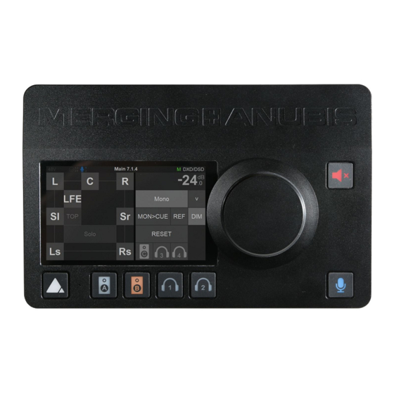
PANEL 1. TFT LCD: High resolution capacitive multi-touch display 2. Home button: Access to Anubis display Main menu cycling and Home page / Settings access 3. Built-in talkback microphone: Mono omnidirectional condenser capsule, located beneath the hole Warning: Avoid touching the built-in microphone or apply pressure while engaged. - Page 17 The distribution choice can be made from the Anubis Monitors Settings. Note: The Anubis Talkback logic is not restricted to the built-in mic and is able to use any other microphone (including Phantom power condenser mics) as well. With even the possibility to setup by software two Talkback mics sending out to different cues or monitors.
-
Page 18: Back Panel
BACK PANEL 1. Power switch: Sets the power of the device to On (pressed) or Off (released). Kensington Security Slot: Lock mechanisms for protection measure. Metal anchor not provided 3. Power Supply: DC Power Supply connector with lock, to prevent accidental disconnection. The DC power input accepts a voltage from 9V to 15V, with a maximum power consumption of 18W. -
Page 19: Front Panel
1. Headphones #1: Independent headphones socket with Stereo jack ¼” connector Warning: Depending of the impedance of your headphone set, it is important to make sure that the Headphones output level is set accordingly. For further details refer to the Anubis Settings>IO>Outputs Headphones description 2. -
Page 20: Anubis Analogue I/Oblock Diagram
ANUBIS ANALOGUE I/O BLOCK DIAGRAM... -
Page 21: How To Connect Merging+Anubis
If the lock release tab is not pushed sufficiently, the cable cannot be removed. Figure 1 Cat5e or Cat6 Ethernet cable Note: A network interface adaptor might be required to connect the Anubis RJ-45 cable to a USB Type A, B or C port or to a Thunderbolt port of your notebook/computer. -
Page 22: How To Connect A Balanced Line Output To An Unbalanced Input
+24 dBu setting is only achievable when driving balanced inputs. This could otherwise cause distortion. Warning: Before you Power Up Anubis, it is recommended to lower the Volume of your Monitor Speakers (if those are connected) and to remove the headphones set from your ears. -
Page 23: Drivers Installation Procedure
DRIVERS INSTALLATION PROCEDURE We recommend that you first read how to POWER Up your MERGING+ANUBIS and only then proceed with the information below. Important. Make sure your Anubis has the most recent firmware installed. Verify the Firmware version by going to the Settings>Info Page. -
Page 24: Mac Os - Vad Premium
You may configure those later. 5. Make sure that your DAW is started and configured to use the Merging RAVENNA ASIO Driver. MassCore users should launch their VS3 Control Panel and have RAVENNA activated. 6. Launch ANEMAN to connect the inputs and outputs of your choice between the Anubis and the RAVENNA ASIO driver (or MassCore). - Page 25 RAVENNA/AES67 Panel from the System Preferences menu. Follow the Virtual Audio Device guide for more details. 4. Launch ANEMAN in order to connect the inputs and outputs between the Anubis and the VAD. 5. Open your preferred DAW and ensure the VAD is selected.
-
Page 26: Linux Os - Alsa Driver
ALSA compatible application • Installation: 1. Connect the Ethernet cable from the Anubis RJ-45 RAVENNA/AES67 port to the Ethernet network port (1Gb) of your computer. 2. Download and Install the Merging LINUX RAVENNA/AES67 Driver. 3. ANEMAN not being supported under Linux, RAVENNA/AES67 connections have to be made from the Advanced Settings RAVENNA pages. -
Page 27: Power Supply
Note: The DC power source can also be coming from a 12V battery. 2. Connect the locking power supply to the rear panel of your Anubis. In order to do so align the two tabs on the power cable's connector to the notches on the Anubis input male connector. -
Page 28: Switching On Merging+Anubis
Hold press the Anubis Home pyramid button for 1 second to open the Home page. The Anubis Home page provides access to the Settings and Preamps pages. The Home page is not in the 3 Main pages cycle. It can anytime be accessed by long pressing the Anubis Home button. -
Page 29: Touchscreen And Navigation
This is required to access the Home page or to open a dialog box. Anubis Rotary Knob The Anubis Rotary Knob can be used for the Volume control, and to control the Preamps Gain, plus settings such as Trim, Delay, Brightness, numeric value entries and for navigation in various Anubis menus. -
Page 30: Anubis Home Page
HOME PAGE STATUS Displays information and notifications about the Anubis status 48V: Will light up red if 48 Phantom power is active on an input channel OV: Overload peak detected, clear the overload by either tapping the meters section or use the... - Page 31 Slave: The Anubis is slave to another PTP Master If multiple Anubis are connected over the same network, one Anubis will be elected the PTP Master. A specific Anubis can require to be the PTP Master by enabling the PTP Master option in the Anubis>Settings>General.
- Page 32 INPUTS OPTIONS: 48V: When enabled it will turn on the 48V phantom power for the channel 1 or 2 of the Anubis meaning that the Phantom power becomes active, typically needed for condenser microphones. Note: Only active on channels set to Mic (Anubis XLR/Combo Inputs 1-2).
- Page 33 Mic mode, with the same gain, an input of +9dBu would generate a signal of +3dB SA-CD. Gain: Tap the channel you wish to adjust. When the Gain is highlighted the Anubis Rotary Control lets you adjust the value in 0.5 dB steps.
- Page 34 None: Max Mic input level +12dBu for 0dbFS (when Gain set to 0) Pad: Attenuates (lowers) the mic input signal level by 12 dB > Max Mic input level +24dBu Boost: Increases (boosts) the mic input signal level by 12 dB > Max input level 0dBu Note: Recommended for Ribbon Microphones that have low output.
- Page 35 The location indicator will show second Preamps page. The Instruments (Hi-Z)/Line inputs 3-4 are the ones located on the front panel of the ANUBIS on 1/4" connectors (6.3 mm). This second Preamps page will give you control over those Preamps.
- Page 36 Input 5 Built-in Talkback: Swipe from Right to Left on the TFT screen again to view the Anubis Input 5 that is dedicated to the built-in Talkback microphone. The Preamps controls for the Input 5 will control the built-in Talkback microphone.
-
Page 37: Dual Gain 32Bit Circuitry
DUAL GAIN 32bit CIRCUITRY While based on the extensive experience of Merging’s Horus and Hapi Preamp and AD converter design, the Anubis engineered Dual Gain 32bit A/D circuitry takes Analog/Digital Conversion design one step further. While using 2 A/D converter channels per input as, in the Horus & Hapi... -
Page 38: Split Channel
SPLIT CHANNEL As seen on the right side of the above block diagram, the Anubis AD front-end topology gives also additional flexibility by offering a split channel functionality, where every input channel has a separate split gain control for sending them to different paths. -
Page 39: Settings
SETTINGS The Anubis Settings are accessible from the Anubis home page, by giving a long press on the Anubis Home button. This will open the Settings page scroll up or down to view and navigate through the settings entries... -
Page 40: Settings Categories Description
The selected mode will determine the device latency over a RAVENNA network. When multiple RAVENNA devices (e.g. Anubis) are connected over a network, they should be configured in order to adjust themselves to the lowest latency that can be globally achieved. - Page 41 Brightness Display Adjust brightness of the TFT display using the Anubis rotary encoder to increase or decrease it. Buttons Intensity Adjust brightness of the Anubis physical buttons by using the Anubis Rotary Knob to increase or decrease the intensity. Cooling Mode: Settings are available for either Low, Mid or High Cooling. This affects the threshold at which the fan will start to operate, with reference to the temperature measured internally.
- Page 42 Note: By default the Anubis IP setting is set to “Auto” configuration mode IP address Set the IP Address for the Anubis unit by using box selection and changing the value using the Anubis rotary knob. Available only with IP Settings = Manual Default: 169.254.x.x...
- Page 43 Set the date 24-Hours format by tapping each field (Hours: Minutes: Seconds) one by one and using the Anubis Rotary Knob to adjust. Note: The Date and Time changes will be saved once you exit the Anubis Settings or if you Save the current configuration from Settings>Exit>Save...
-
Page 44: Presets Settings
A prompt message box will ask you to confirm the save or load of a preset. Note: During the Preset loading the Anubis Mute button will blink muting all monitors for a short period of time. Warning: A Reboot to Factory will reboot the Anubis to the default factory settings, the current configuration will be lost, but all the saved Presets will be kept and can be reloaded. - Page 45 Select to delete a Source upon confirmation in message dialog Enable or disable a source Disabling a source will hide it from the Main Anubis menu pages. Doing so will not delete the Source but simply hide it with a gray icon it can be re-enabled at any time.
- Page 46 Trim Trim the level of an entire Source, apply a trim by turning the Anubis Rotary Knob. Range: -12dB to 12dB Note: Trim is after the initial analog gain stage, so if the channel input is clipping, Trim cannot fix it.
- Page 47 Select to delete a Monitor set upon confirmation in message dialog Enable or disable a Monitor Disabling a Monitor will hide this one from the Main Anubis menu pages. Doing so will not delete the Monitor but simply hide it with a gray icon it can be enabled back at any time.
- Page 48 Set controls: Mute, Solo, Solox, Polarity, Downmix, Ref and Dim will not be injected in the Cue. Trim Trim the level of a Monitor set, apply by turning the Anubis Rotary Knob. Range: -12dB to 12dB An individual Channel Trim is available for each channel (refer to the Channel description below)
- Page 49 Sources or Monitors. Trim: A channel trim is available for each speaker. Range: -12dB to 12dB Delay: Set a delay to the speaker of your choice. Apply by turning the Anubis Rotary Knob. Range: 0ms to 150ms by steps of 1ms...
-
Page 50: Bass Management
Bass Management is available for Speaker Set Monitor sets with at least one LFE channel type. Based on the ZMAN Anubis board that offers built-in high-quality filters directly processed into the FPGA. Those will apply a crossover frequency from all channels (except LFE and LF2) and route low frequency information to the LFE channel(s). -
Page 51: Bass Management Signal Flow
Bass Management Signal flow... - Page 52 Apply Crossfeed to make audio played through headphones sound more natural, as when listening to a pair of external speakers. Select and turn the Anubis Rotary Knob to apply. Range: 0 (no crossfeed applied) to 100% (equivalent to mono).
- Page 53 TALKS Settings The Anubis Talkback logic is not restricted to the built-in mic but is able to use any other microphone (including Phantom power condenser mics) as well. With the possibility to setup by software two Talkback or Listen mics sending out to different Speaker Set/Headphones monitors.
- Page 54 Trim: Apply a trim value to the Talk source Patch: Patch the Talk source, you can choose the local Built-in Mic, any Anubis input where you would connect a Microphone or an AoIP Stream that could be a Microphone connected to another RAVENNA/AES67 compliant device.
- Page 55 OUTPUTS Settings Global Outputs Setting Roll Off Filter: Sharp: Offers a flat frequency response up to 22kHz, within 0.2dB, which has the tradeoff of 35 samples latency. Slow (default): Offers the lowest latency of 9 samples, with the tradeoff of a gentle frequency response attenuation starting around 17kHz (- 0.01dB) and reaching -3dB at 21.6kHz Apodizing: Fast Roll-Off filter, Linear phase filter.
- Page 56 Brickwall: Ensures rejection of more than -100dB at Nyquist (0.50 x FS). Latency of 35 samples XLR 1/2: Line output level of the physical XLR outputs 1 and 2 located at the back to the Anubis Max Output Level: +18dBu or +24dBu...
- Page 57 Warning: The Anubis Headphones output level can make your headphones very loud if it is turned up too high, and that could cause permanent hearing damage. Please be careful with your ears when using the +18dBu setting.
-
Page 58: Info Settings
Number along with additional information on the Anubis status: Temperature, CPU and Memory usage. Note: Anubis users should regularly check if a new firmware is available. It is important to update to the latest firmware in order to benefit from the latest improvements and fixes. Follow the firmware update procedure for all details. -
Page 59: Exit Settings
Save the current Anubis configuration Note: The Anubis entire configuration is saved every 2 minutes, and as well every time you exit the Anubis Settings. If changes are applied when in the Anubis Settings and you plan to power off the Anubis while in the Settings, it is recommended to first perform a Save configuration. -
Page 60: Anubis Monitor Mission Control
The Anubis Monitor Mission allows you to be in complete control of your monitoring; reference monitors, near-field monitors, headphones, sources, surround mix, downmix, etc. - Page 61 Monitor Mission Engine Bypassing the Anubis Monitoring Engine will prevent control over Volume (Rotary), Trim, Mute and more. Such connection could be desired for direct IO use and for connecting for example, an A/D directly to a D/A for Effect Inserts usage. For Monitoring Control purposes this is it not recommended.
-
Page 62: Sources Vs. Monitors Fundamentals
It is fundamental with the Anubis Monitoring Mission to understand the importance of using Sources (Mixer inputs) and Monitors (Mixer outputs), as this is the base of the Anubis Monitoring Engine. Not doing so will bypass the Monitoring engine and prevent proper Monitor Control (Volume control, Mute, Trim...). -
Page 63: Different Monitor Types
Recommended to be used when a specific mix of Sources is needed for a chosen Monitor set or when recording to produce a low-latency Cue mix for the performer foldback. Each of the three types of Anubis Monitors have their unique set of features and possibilities. Refer to the table below for more details... - Page 64 The Monitor mission has 3 main pages, press the Anubis home button to cycle between those. Monitor Page Source page Meters page Single tap on the Anubis Home button to cycle between the three MONITOR Pages. At all times return to the Anubis Home page (Settings/Preamps) by a long press on the Anubis Home button...
-
Page 65: Monitor Page
Settings Sources and Monitors section for all details. Your speaker set will come into display once you select the key that it is assigned to. By default, Anubis comes with some predefined Monitor sets that can be used right away, those can be reconfigured or deleted as one... - Page 66 Tap the Speaker control box to open the dialog, for Speaker controls such as: Mute, Solo, SoloX and Phase option controls. Those functions can be applied to the Speaker(s) of your choice. Mute: Mute function available for each speaker in your set. Tap a speaker to cut its signal. Figure 10 Example: Muting LFE Solo: Solos the Speaker by muting all other speakers.
- Page 67 Polarity: Invert the polarity of a chosen speaker in your set up. Tap a speaker to invert its polarity, this can be useful to check or fix phase cancellation problems. The polarity is a latching function that can be applied in addition to Mute/Solo or SoloX options. Figure 13 Example: Polarity applied to L and R speaker channels Clear: Use the Clear function to re-initialize the Speaker controls, this will remove all applied controls to the speakers.
- Page 68 A total of 4 Softkeys are available and can be used to control extra Monitor Sets, Cues or Headphones. The SoftKeys mapping must first be configured from the Anubis Settings>Monitors under the Monitor Set settings. Tap a Softkey to activate its Monitoring just as you would with a...
- Page 69 Downmix Table Monitor Channels - Types vs. Downmix formats available.
- Page 70 SOURCE PAGE The Source page allows the operator to select the different Sources he wishes to monitor. You can exclusively select a Source or sum multiple Sources and as well apply level Trim. The Sources page also gives you Monitor Controls, with similarities to the Monitor page. Source Type This first section on the left indicates the Source Type name as well as the Metering of the Source, once this one has been configured and patched form the Settings>Sources.
- Page 71 Source Trims are applied to all monitors and can be adjusted by holding the finger on the Source name while turning the Anubis Rotary knob. Turn the Rotary clockwise to increase a Trim value and turn the Rotary counter-clockwise to decrease a Trim value.
- Page 72 Select to recall your reference level, the default Reference level is set to -20 dB and can be configured from the Anubis Settings>Monitor Level Turns the selected Speaker Set output dimmer ON, the default Dim level is set to -20 dB and can be configured from the Anubis Settings>Monitor Level...
-
Page 73: Meters Page
METERS PAGE The Meters page provides an overview of the Sources and Monitors metering, along with some controls over the Sources and Monitors. Sources Meters Metering overview of all the Sources, each source with full details of peak-meters and type per channel. - Page 74 Trim the level of a Source or Monitor by first selecting it, while holding the meter region pressed, adjust the trim by turning the Anubis Rotary knob. Turn the Rotary clockwise to increase the Trim value and turn the Rotary counter- clockwise to decrease the Trim value.
-
Page 75: Anubis Use Cases
Procedure) and ensure that you have correctly connected and powered up your Anubis. Connect your Active Monitors (or Power Amp) to the Anubis physical Outputs XLR 1 and 2 and/or TRS outputs 3-4 if you have alternate Monitors in your setup. - Page 76 1. In order to connect your DAW playback to Anubis you must first have a Source available to host your DAW Playout Stream 1-2 (if stereo) Note: Ex-factory Anubis comes with a DAW 1-2 Source. If this one is not available in the Sources page, create it, refer to the Settings>Sources manual section.
- Page 77 5. Return to the Main Anubis Source page in order select which source and from which Monitor set you will monitor. First select the Monitor Set (e.g. Anubis A or B button), then select the DAW 1-2 Source to monitor it.
- Page 78 Note: The Speakers Set mode and Headphones mode listen to the same Sources selection. In order to listen to different Sources, a Monitoring Cue must be configured (refer to the Settings>Monitors Cue mode section) You are ready to start your Anubis Monitoring Mission and have full control over your DAW monitoring.
-
Page 79: Surround Monitoring Control Setup
Using Anubis monitoring controls with a RAVENNA/AES67 device such as Horus or Hapi integrated in a network Studio setup and used for their multichannel capabilities. In the setup here Anubis will be the Monitoring Controller for a 5.1 surround monitor set, played out from a DAW multichannel bus through the Horus DA8. - Page 80 4. Create a new Monitor Set. Exit the Source Setting and enter the Settings>Monitor Page where you can create a new Monitor Set. 5. Within the new Monitor, select a given name from the Anubis predefined Monitor names and choose a numeric/alphabetical tag. Assign the Monitor to the button of your choice and most importantly choose your Monitor Set layout from the Type entry field listing (5.1 / LRC).
- Page 81 5. Exit the Settings in order to return to the Anubis Source Page where a new “Horus 5.1 LCR” Source should be available along with a new Monitor 5.1 Surround Speaker set on the VirtualKey 1. 6. Launch the Merging’s ANEMAN application (that should previously have been installed on your system).
- Page 82 Figure 18 Horus D/A 8 Source connected to the Anubis Surround 5.1 Monitor Set. 10. Connect your DAW multichannel output bus to the Horus 5.1 available output stream Figure 19 Pyramix 5.1 LCR Multichannel Bus 11. Return to the Anubis Source Page and select the Horus 5.1 Source...
-
Page 83: Surround Monitoring On Stereo Speaker Set
Figure 21 Anubis Monitor Page Surround Monitoring on Stereo Speaker Set User who wish to monitor a Surround source without a multi-speakers set up can use the Anubis monitoring engine to downmix to Stereo and monitor the surround source with a pair a Speakers. - Page 84 Setup could be applicable in Broadcast where an Anubis station could monitor streams from various production rooms or in an educational classroom where a teacher could monitor each student station from his local Anubis and as well in Live where a sound engineer could monitor each musician Anubis stream.
- Page 85 Settings>Source. By factory one AoIP source listener should already be available. Note: a Source Listener has very few parameters to configure, only name and trim are applicable 4. From the Anubis Source Page open the AoIP Listener dialog by tapping the AoIP entry on the left 5.
-
Page 86: Recording Setup
Anubis. Connect your microphones to the XLR combo inputs 1-2 located at the back of the Anubis, your Guitar or Bass can be directly connected to the Hi-Z instrument input at the front Input 3. - Page 87 2. In order to monitor your Microphones and Instrument input, the operator can use the already available default sources. The Anubis default factory settings come with a MIC/Line 1-2 Source and Inst/Line 3 Source. If those sources are not available or if you wish to use different sources, please refer to the Settings>Sources manual section.
- Page 88 ANEMAN adding Mics/Line 1-2, Inst/Line 3 connections while having DAW Source 1-2 already connected. 4. Return to the main Anubis Source page in order to select a source to monitor. Enable the SUM option and select multiple sources to monitor those.
- Page 89 5. Access the Preamps control page. Now that you can Monitor your inputs open the Preamps page by pressing the Anubis Home button for a second. This will open the Home page where you can select the Mic Pre page.
- Page 90 7. How to create a Cue Monitor. First enter the Settings>Monitor page and create a new Monitor Set. Tap this new entry to enter the monitor setting. Note: Users can edit existing Monitor sets and change their mode to Cue. 8.
- Page 91 Note: To configure the Built-in Talkback for the performer's headphones, refer to the Talkback use case. You are ready to start recording with Anubis and have a Musician using an Ultra-Low Latency Cue (Q) Monitor set.
-
Page 92: Talkback Network Setup
Anubis is used as the Monitoring control with integrated talkback. Here the sound engineer uses the Anubis built-in Talkback #1 to communicate with a stage technician. The producer communicates with the conductor using a second talkback #2 using an external microphone connected to one of the Anubis input. - Page 93 8. On the Talk 2 we have configured it to use the Microphone connected into Anubis XLR/Combo input 1 located at the back of the Anubis and have it triggered from a GPI, which in the example here would be a footswitch connected to the GPI input located at the back of the Anubis.
- Page 94 12. Configure your second Monitor set to use the Talkback using Talk B. If you wish to use a second RAVENNA/AES67 device, first make the connection in ANEMAN, and then patch Talk 2. You are now ready to communicate using the Anubis Talkback...
- Page 95 DAW. The DAW playout RAVENNA/AES67 source stream would be monitored from ANUBIS. Connect your Keyboard MIDI Thru to a MIDI Sound Module and this one to the Anubis analog inputs, then configure your DAW for recording the Anubis inputs.
- Page 96 The Anubis MIDI I/O provides a MIDI connection between class compliant Core MIDI devices such as keyboards, drum machines, sound modules and other controller. The MIDI IN and MIDI OUT ports located at back of the Anubis use a 1/4" jack sockets for connection of external MIDI equipment, refer to the User Manual Appendices section for details on the MIDI cable pinout.
- Page 97 ProTools on Mac example Note: The MIDI Input and Output located on the back of the Anubis can also be used to send and receive MIDI timecode (MTC). By doing so, you can use an application supporting MTC to synchronize a multitrack recorder (MTR/DAW) and MIDI devices.
-
Page 98: Monitoring Web User Interface
MONITORING WEB USER INTERFACE Remote control your Anubis Monitoring through any tablet or web browser by opening the Web User page. The Anubis Monitoring Web User Interface combines all three pages of the Monitoring Mission into a single web page. - Page 99 Anubis entry. Mac Users: Once Anubis is properly connected to your Mac, open the VAD Panel and click on the Anubis Icon. This will open the Anubis Monitoring Web Access page in your default browser. Users can also open the Web User interface page from ANEMAN or MT Discovery by clicking on the Anubis.
- Page 100 Wi-Fi Access Point. Find the Anubis IP address under Settings > General into the Network IP address entry Type your Anubis IP address in the web browser and press enter to open the Remote Web User Interface This method works with Chrome, FireFox, Opera and Safari, but does not work with Microsoft Edge.
-
Page 101: Anubis Firmware Udpate Procedure
- ANEMAN v1.1.7 and above. Download from https://www.merging.com/anubis/download - An internet connection to download the latest Firmware or Maintenance Mode - Connecting the ethernet interface of the Anubis to a Mac or PC system for the update procedure PROCEDURE 1. Install ANEMAN 2. - Page 102 7. Use the “Select File” button to select your firmware 8. This will open the explorer form where you can load the Firmware 9. Once the firmware is selected press the Update button Note: During the Firmware update the Anubis Mute button will blink muting all monitors...
- Page 103 ANUBIS TFT, by selecting “Reboot Device” 12. You should now be on the latest Firmware. You can verify the Firmware version of your Anubis by opening the Info page (Long press Home button) and navigate to Settings>Info...
-
Page 104: Anubis Technical Specifications
ANUBIS TECHNICAL SPECIFICATIONS GENERAL Case Material Premium machined and anodized aluminium Dimensions 200 x 128 x 40mm Weight 950 gr Top Panel Display Capacitive Touch, TFT LCD 800 x 480 pixels resolution 16:9 Aspect ratio Rotary Encoder Anodized aluminum + Black rubber O-ring... - Page 105 Max Line Input Level +24 dBu Input Impedance (Differential) ~ 10kΩ THD+N Preamp + A/D 1kHz @ 0 dBFS < - 104 dB (0.0006%) Interchannel Crosstalk @ 1kHz < -140 dB Sensitivity Range for 0 dBFS (Software controlled) +24 dBu to -42 dBu INSTRUMENTS / Hi-Z &...
- Page 106 HEADPHONES Headphone Jacks 2 Independent ¼” TRS Female Stereo 6.3 mm Dynamic Range (A-weighted, typ.) High / Low < -122 dB / - 117 dB Max output Level High / Low 17.1 dBu / 7.8 dBu Frequency response +0/-0.2dB @ fs = 48 kHz 6 Hz –...
-
Page 107: Appendices
APPENDICES MIDI CONNECTOR Female 6.3 mm - 1/4" TRS connector PIN OUT GPIO CONNECTOR Female 6.3 mm - 1/4" TRS connector GPI Application Example - Footswitch triggering... - Page 108 GPO Application Example 1 – Record On Led 5 [ �� ] − �� ��_������ �� [��] ������ 440 [ Ω ] + �� [Ω] ������ 5 [ �� ] − �� ��_������ − 440 [ Ω ] �� ������ ��...
- Page 109 Monitoring Engine and then going to a Monitor set. Cannot Apply the Dim or Wrong Monitor type This is expected as each of the Anubis 3 types of Monitor set have their own features. Refer to the Monitors Tables. Reference parameters to a In order to use Dim, the Reference level and other features on a Headphones Set.
- Page 110 Launch ANEMAN and in the world view create a New Sampling rate Rate Zone Zone, select your RAVENNA ASIO or VAD driver and drag this one on the Crown within the Zone, then drag the Anubis in the Zone as well. Monitor your PC sounds Requires third party Refer to the Merging’s Knowledge Database WDM -ASIO configuration...
-
Page 111: For More Information
FOR MORE INFORMATION MERGING+ANUBIS Downloads https://www.merging.com/anubis/download MERGING+ANUBIS Knowledge Database, FAQs and Tutorials https://confluence.merging.com/display/publicdoc/MERGING+ANUBIS Merging Support support@merging.com MERGING+ANUBIS Website https://www.merging.com/products/anubis Merging YouTube Channel https://www.youtube.com/channel/UCR5q_dlb9dYnXTrVDWMshgw...
Need help?
Do you have a question about the Anubis and is the answer not in the manual?
Questions and answers